EP4556888A1 - Ein automatisiertes verfahren zur bestimmung des zustands eines optischen systems - Google Patents
Ein automatisiertes verfahren zur bestimmung des zustands eines optischen systems Download PDFInfo
- Publication number
- EP4556888A1 EP4556888A1 EP23220649.0A EP23220649A EP4556888A1 EP 4556888 A1 EP4556888 A1 EP 4556888A1 EP 23220649 A EP23220649 A EP 23220649A EP 4556888 A1 EP4556888 A1 EP 4556888A1
- Authority
- EP
- European Patent Office
- Prior art keywords
- optical system
- signal
- present
- sample
- signals
- Prior art date
- Legal status (The legal status is an assumption and is not a legal conclusion. Google has not performed a legal analysis and makes no representation as to the accuracy of the status listed.)
- Withdrawn
Links
Images


Classifications
-
- G—PHYSICS
- G01—MEASURING; TESTING
- G01N—INVESTIGATING OR ANALYSING MATERIALS BY DETERMINING THEIR CHEMICAL OR PHYSICAL PROPERTIES
- G01N21/00—Investigating or analysing materials by the use of optical means, i.e. using sub-millimetre waves, infrared, visible or ultraviolet light
- G01N21/17—Systems in which incident light is modified in accordance with the properties of the material investigated
- G01N21/47—Scattering, i.e. diffuse reflection
- G01N21/4738—Diffuse reflection, e.g. also for testing fluids, fibrous materials
- G01N21/474—Details of optical heads therefor, e.g. using optical fibres
-
- G—PHYSICS
- G01—MEASURING; TESTING
- G01N—INVESTIGATING OR ANALYSING MATERIALS BY DETERMINING THEIR CHEMICAL OR PHYSICAL PROPERTIES
- G01N21/00—Investigating or analysing materials by the use of optical means, i.e. using sub-millimetre waves, infrared, visible or ultraviolet light
- G01N21/01—Arrangements or apparatus for facilitating the optical investigation
- G01N21/15—Preventing contamination of the components of the optical system or obstruction of the light path
-
- G—PHYSICS
- G01—MEASURING; TESTING
- G01N—INVESTIGATING OR ANALYSING MATERIALS BY DETERMINING THEIR CHEMICAL OR PHYSICAL PROPERTIES
- G01N21/00—Investigating or analysing materials by the use of optical means, i.e. using sub-millimetre waves, infrared, visible or ultraviolet light
- G01N21/17—Systems in which incident light is modified in accordance with the properties of the material investigated
- G01N21/47—Scattering, i.e. diffuse reflection
- G01N21/4785—Standardising light scatter apparatus; Standards therefor
-
- G—PHYSICS
- G01—MEASURING; TESTING
- G01N—INVESTIGATING OR ANALYSING MATERIALS BY DETERMINING THEIR CHEMICAL OR PHYSICAL PROPERTIES
- G01N21/00—Investigating or analysing materials by the use of optical means, i.e. using sub-millimetre waves, infrared, visible or ultraviolet light
- G01N21/84—Systems specially adapted for particular applications
- G01N21/88—Investigating the presence of flaws or contamination
- G01N21/94—Investigating contamination, e.g. dust
-
- G—PHYSICS
- G01—MEASURING; TESTING
- G01N—INVESTIGATING OR ANALYSING MATERIALS BY DETERMINING THEIR CHEMICAL OR PHYSICAL PROPERTIES
- G01N21/00—Investigating or analysing materials by the use of optical means, i.e. using sub-millimetre waves, infrared, visible or ultraviolet light
- G01N21/01—Arrangements or apparatus for facilitating the optical investigation
- G01N21/15—Preventing contamination of the components of the optical system or obstruction of the light path
- G01N2021/155—Monitoring cleanness of window, lens, or other parts
- G01N2021/157—Monitoring by optical means
-
- G—PHYSICS
- G01—MEASURING; TESTING
- G01N—INVESTIGATING OR ANALYSING MATERIALS BY DETERMINING THEIR CHEMICAL OR PHYSICAL PROPERTIES
- G01N21/00—Investigating or analysing materials by the use of optical means, i.e. using sub-millimetre waves, infrared, visible or ultraviolet light
- G01N21/17—Systems in which incident light is modified in accordance with the properties of the material investigated
- G01N21/47—Scattering, i.e. diffuse reflection
- G01N2021/4704—Angular selective
- G01N2021/4709—Backscatter
-
- G—PHYSICS
- G01—MEASURING; TESTING
- G01N—INVESTIGATING OR ANALYSING MATERIALS BY DETERMINING THEIR CHEMICAL OR PHYSICAL PROPERTIES
- G01N21/00—Investigating or analysing materials by the use of optical means, i.e. using sub-millimetre waves, infrared, visible or ultraviolet light
- G01N21/17—Systems in which incident light is modified in accordance with the properties of the material investigated
- G01N21/47—Scattering, i.e. diffuse reflection
- G01N21/4738—Diffuse reflection, e.g. also for testing fluids, fibrous materials
- G01N21/474—Details of optical heads therefor, e.g. using optical fibres
- G01N2021/4742—Details of optical heads therefor, e.g. using optical fibres comprising optical fibres
- G01N2021/4745—Fused bundle, i.e. for backscatter
-
- G—PHYSICS
- G01—MEASURING; TESTING
- G01N—INVESTIGATING OR ANALYSING MATERIALS BY DETERMINING THEIR CHEMICAL OR PHYSICAL PROPERTIES
- G01N2201/00—Features of devices classified in G01N21/00
- G01N2201/12—Circuits of general importance; Signal processing
- G01N2201/129—Using chemometrical methods
- G01N2201/1296—Using chemometrical methods using neural networks
-
- G—PHYSICS
- G02—OPTICS
- G02B—OPTICAL ELEMENTS, SYSTEMS OR APPARATUS
- G02B27/00—Optical systems or apparatus not provided for by any of the groups G02B1/00 - G02B26/00, G02B30/00
- G02B27/0006—Optical systems or apparatus not provided for by any of the groups G02B1/00 - G02B26/00, G02B30/00 with means to keep optical surfaces clean, e.g. by preventing or removing dirt, stains, contamination, condensation
Definitions
- optical system condition monitoring including an automated method for determining a condition of an optical system, the condition comprising the presence of contamination in the optical system or the quality of focus of the optical system, the optical system comprising means for providing a sample and optical means, and being configured to produce a backscattering or forward scattering signal upon illumination.
- a challenge arises in obtaining long term, reliable and reproducible optical measurements, particularly when dealing with complex fluid samples and complex fluid samples, including bodily based fluids or pharmaceutical solutions.
- Such challenge relates to optical surfaces being directly exposed to the sample of interest, leading to potential contamination of the optical means, as it is needed a measure of how contaminated the optical means may be.
- the use of cleaning agents can remove most of the (biological) contaminants, as is the case of the agents used to clean endoscopic probes.
- the outcome of such a cleaning step still needs to (a) be continuously validated to ensure that cross-contamination from one sample to the next is avoided and (b) that the optical signals obtained are reproducible and reliable throughout long term measurements.
- Prior art solutions which seek to determine quality of focusing in optical systems usually are based on an iterative protocol that obtains images or signals at different sample positions, followed by an algorithm that optimises for image contrast and/or signal levels. Such an approach typically does not provide a direct quantitative measure to monitor changes in the optical signal over time.
- the position of the lens as well as the detectors are fixed without the ability to take images at different positions, as is normally the case with lensed optical fibres.
- the quality of the optical focusing is directly affected by the cleanliness, aberrations and optical quality of surfaces the light passes through as any deviation from a flat phase-front will lead to an increase in the focal spot size, lowering the obtained optical signal and preventing quantitative measurements.
- This condition usually leads to integrating a measurement that enables to monitor the quality and degradation of the optical signal over time and that does not require optical imaging.
- This quality factor is typically measured by taking at least five images of a beam diameter emitted by an optical system in different positions along the optical axis, which is not possible in applications without an imaging capability or when light is tightly focused by a lens with a high numerical aperture due to the pixel size of CCD or CMOS based imaging devices being smaller than the focal spot size.
- this quality factor of the focal spot size can be characterised by scanning a single subwavelength size calibration particle through the focal area and collecting the optical scattering at each point where the calibration particle is placed in the focal region. This is a technically demanding, slow and time consuming process that is severely hampered by the limited signal that can be collected from subwavelength sized particles.
- fluorescent nanoparticles and/or fluorescence imaging approaches are used.
- the solutions of the present disclosure address such issues, enabling a reliable determination of the condition of an optical system, in particular focused on the level of contamination and quality of focus of such optical system, enabling its long term, reliable and reproducible operation.
- the present disclosure includes an automated method for determining a condition of an optical system, the condition comprising the presence of contamination in the optical system or the quality of focus of the optical system, the optical system comprising means for providing a sample and optical means, and being configured to produce a backscattering or forward scattering signal upon illumination.
- the method comprises the steps of:
- the baseline signal may be established from more than one reference signal, the reference signals being backscattering or forward scattering signals and each corresponding to a reference sample provided in the means for providing a sample of the optical system or of an identical optical system.
- Establishing a baseline signal may comprise applying at least one metric to each of the reference signals, therefrom extracting at least one feature from each of the reference signals and determining a threshold or an expected value, the comparison between the present signal and the baseline signal comprising comparing the present signal with such threshold or expected value obtained from the reference signals.
- the at least one metric applied to each of the reference signals may comprise one or more of voltage peak-to-peak, mean, standard deviation, Skewness, Kurtosis and root mean square (RMS).
- the reference samples may be of a clean solvent, such as water, optionally ultrapure water, optionally Milli-Q ultrapure water.
- the method may further comprise training a machine learning classifier with the more than one reference signals which are considered to be conform or non-conform with regard to the condition to be determined and, optionally with:
- the machine learning classifier may be a supervised deep learning classifier.
- the method may further comprise determining a condition of an optical system upon providing a sample to be analysed in the means for providing the sample and cleaning the optical system or upon providing a sample to be analysed in the means for providing the sample.
- the determination of the presence of contamination in the optical system may comprise comparing the present signal with the threshold or expected value obtained from the reference signals by determining how much of the present signal:
- the threshold may comprise a higher threshold and a lower threshold.
- the comparison may correspondingly be performed by determining:
- Comparing the present signal with the baseline signal may comprise applying at least one metric to the present signal, thereby extracting at least one feature from the present signal, and comparing such feature extracted from the present signal with the threshold or expected value.
- the metric applied to the present signal may be one or more of voltage peak-to-peak, mean, standard deviation, Skewness, Kurtosis and root mean square (RMS).
- the determination of the quality of focus of the optical system may comprise obtaining a plurality of present signals from a plurality of corresponding samples and comparing the present signals with the said baseline signal, each of the corresponding samples and the reference samples comprising a clean solvent, such as water, and nanoparticles subsequently provided in the means for providing a sample.
- a clean solvent such as water
- the clean solvent may be water.
- Water may be ultrapure water or Milli-Q ultrapure water.
- the reference samples containing the clean solvent and nanoparticles may consist of an original sample of clean solvent and nanoparticles and a plurality of dilutions of the original sample in the clean solvent, each dilution having an order corresponding to a lower concentration of nanoparticles as regards the original sample and a prior dilution, and the current samples containing clean solvent and nanoparticles consist of an original sample of clean solvent and nanoparticles and a plurality of dilutions of the original sample in the clean solvent, each dilution having an order corresponding to a lower concentration of nanoparticles as regards the original sample and a prior dilution,
- the clean solvent may be water.
- Water may be ultrapure water or Milli-Q ultrapure water.
- the comparison of the present signal with the baseline signal may comprise extracting at least one feature from the present signals and comparing such extracted features the threshold or expected value obtained from the reference signals.
- Establishing a baseline signal for such optical system may comprise:
- the reference feature and the present feature may consist of a value obtained from the metrics of voltage peak-to-peak, mean, standard deviation, Skewness, Kurtosis and root mean square (RMS), the further reference metric and the further present metric consisting of linear regression and the further reference feature and the further present feature consist of a slope obtained from the linear regression, the slope obtained from the further present metric being compared with one or more slopes obtained from the further reference signals.
- RMS root mean square
- the present disclosure further comprises a non-transitory storage media including program instructions executable by an electronic processor for implementing the method of the present disclosure.
- the present disclosure further comprises a device for determining a condition of an optical system, the condition comprising the presence of contamination in the optical system or the quality of focus of the optical system, the device comprising an electronic processor for implementing the method of the present disclosure.
- the present disclosure further comprises an optical system configured to determine an own condition, the condition comprising the presence of contamination in the optical system or the quality of focus of the optical system, the optical system comprising means for providing a sample, optical means and the device of the present disclosure.
- the optical system may further comprise:
- the coherent light beam may be a laser beam
- the laser beam may be a visible light laser beam or an infrared laser beam.
- the automated method for determining a condition of an optical system of the present disclosure enables that such condition is determined in a fully automated form, only based on data - current signals - obtained from the system.
- the presence of contamination may result in determining whether the optical system is contaminated and cannot operate, the results of which being compromised, or is not contaminated and can continue its operation.
- the quality of focus may result in determining whether the optical system has a quality of focus which does not allow its continued operation, the results of which being compromised, or has a quality of focus such that it can continue its operation.
- the cleaning step may be repeated, and another determination according to the method of the present disclosure performed after such cleaning repetition.
- the determination of a condition may refer to only part of the optical system.
- the optical system may include an element, optical means, which are in contact with the means for providing a sample or in contact with a sample when provided in the means for providing a sample.
- the optical means may consist of a focusing element.
- the optical means are not in contact with the means for providing a sample or with a sample when provided in the means for providing a sample, it still may be that the provision of a sample in the means for providing a sample leads to an exposure of the optical means, whereby at least part of the sample contacts and thereby contaminating the optical means.
- the optical means may include a fibre optic fixedly coupled to the means for providing a sample.
- the fibre optic may form a focusing element of the optical system.
- the optical system is further configured to produce a backscattering or forward scattering signal upon illumination.
- An example of illumination may include the emission of a coherent light beam into the means for providing a sample, such that a sample provided therein is hit by such coherent light beam.
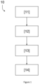
- the method [10] comprises the following steps, as represented in Figure 1 :
- the method of the present disclosure allows to provide a simple and reliable approach at determining the desired condition of the own optical system, without resorting to further equipment or to complex processing.
- the determination of the condition of the optical system provides that the automated method may further perform decision making regarding the need to a) redo a certain measurement of a sample, b) perform additional cleaning of the optical system, or c) replace one or more elements of the optical system.
- the optical means of the optical system may comprise or even consist of one or more focusing elements.
- Such focusing elements are closer or in contact with the means for providing a sample and, thus, with the actual sample (as previously referred). This leads to potential contamination and impact on the quality of focus, e.g., due to cleaning of such optical elements.
- the focusing element comprises or consists of a fibre optic provided fixedly on the means for providing a sample.
- the focusing element may be permanently in contact with the sample (when a sample is provided on the means for providing a sample).
- the fibre optic as focusing element leads light, e.g., resulting in a backscattering of forward scattering signal, towards further optical elements.
- the optical system contains further elements.
- the optical system is configured to, in its operation to obtain a signal from a sample to be analysed provided in the means for providing a sample, obtain a backscattering or forward scattering signal of such sample.
- the optical system may thus comprise:
- the coherent light beam may, for instance, be a laser beam.
- the emitted coherent light beam may be modulated by a predefined modulation frequency.
- optical system Further details of the optical system are provided below.
- the establishment of a baseline signal corresponds to a calibration stage of the method.
- the establishment of a baseline signal may involve obtaining more than one reference signal - a plurality of reference signals -, the reference signals being backscattering or forward scattering signals and each corresponding to a reference sample provided in the means for providing a sample of the optical system or of an identical optical system.
- the reference samples may thus be obtained from the actual optical system being analysed or from an identical optical system.
- An identical optical system may be defined as an optical system containing the same optical elements as the optical system under analysis through the method of the present disclosure.
- condition may be determined based on reference samples provided in the optical system under analysis prior to any sample being provided in such optical system, other than a reference sample.
- condition may be determined based on reference samples provided in an identical optical system prior to any sample being provided in such optical system, other than a reference sample.
- reference signals may be used.
- Establishing a baseline signal comprises applying at least one metric to each of the reference signals, therefrom extracting at least one feature from each of the reference signals and determining a threshold or an expected value, the comparison between the present signal and the baseline signal comprising comparing the present signal with such threshold or expected value obtained from the reference signals.
- the provision of at least one metric allows to characterise the reference signals and to therefrom obtain relevant information to define a threshold or expected value.
- metrics are voltage peak-to-peak, mean, standard deviation, Skewness, Kurtosis and root mean square (RMS).
- the voltage peak-to-peak of a plurality of reference signals may be used to determine one or more thresholds.
- a higher threshold may be defined, as well as a lower threshold. Both may also be defined.
- such threshold may correspond to a threshold below which the optical system is considered to be operating without contamination or with a quality of focus which enables its continued operation.
- the present signal may then be obtained and compared with such metric, for instance to determine whether such signals are out of the range defined by such metrics.
- the Y-axis contains data of Amplitude of the voltage signal in mV, over time provided in seconds in the X-axis.
- a metric such as the illustrative voltage peak-to-peak can thus be applied.
- the reference samples may be of a clean solvent, such as water, optionally ultrapure water, optionally Milli-Q ultrapure water.
- the baseline signals of Figure 2 refer to three different samples of ultrapure - Milli-Q-water, for which six different reference signals were obtained.
- Ultrapure water is free from any contaminants that could be detected through the elastic scattering measurements, and thus defines a solid baseline.
- the method of the present disclosure may involve artificial intelligence, more particularly machine learning, enabling that the comparison and the determination steps are performed by a machine learning classifier.
- a machine learning classifier is trained with the more than one reference signals which are considered to be conform and non-conform with regard to the condition to be determined and, optionally, with:
- the number of reference signals influences the robustness with the baseline signal, and the corresponding comparison with a present signal.
- the number of reference signals may be higher than 10, 20, 30, 40, 50, 60, 70, 80, 90, 100 or higher.
- the number of reference signals may specifically be of 96.
- a baseline signal may be used during the operational life of an optical system.
- the method of the present disclosure may further comprise that the comparison and the determination steps are performed by a machine learning classifier.
- Machine learning is a subfield of artificial intelligence (Al) that focuses on the development of algorithms and statistical models that are aimed at training computer systems to automatically identify patterns, make predictions, or make decisions based on data.
- ML encompasses itself a vast variety of algorithms that include, for instance, reinforcement learning, convolutional neural networks, random forests, among many others.
- the solution of the present disclosure may specifically involve a supervised approach that builds upon existing information, such as backscattering or forward scattering signals previously validated by a human operator as conform or non-conform with the condition, to detect conform/non-conform signals.
- the method thus comprises previously training a machine learning classifier, specifically with the more than one reference signals, which are considered to be conform and quality focuses which are considered to be non-conform.
- the machine learning classifier may be a supervised deep learning classifier.
- the machine learning classifier may operate according to the representation of Figure 6b , including the steps of:
- a battery of experiments is run, in particular include analysing water or ultrapure water or Milli-Q water before the optical system is exposed to any other material, analysing complex samples - such as complex liquid biological samples (biosamples) - that will potentially contaminate the optical system in the absence of further cleaning protocols applied to the system.
- backscattering and forward scattering signals are obtained and analysed, for instance for Milli-Q water and right after a certain complex liquid biosamples has been provided in the optical system (in the means for providing a sample), both with and without previous cleaning.
- These signals may then be classified into groups of (i) conform and (ii) non-conform subsequently being used, based on such information, to train a machine learning classifier, which may be a deep learning algorithm.
- a conform signal corresponds to non-contaminated, while a non-conform signal corresponds to contaminated.
- a conform signal corresponds to a quality focus which is considered to be conform
- a non-conform signal corresponds to a quality focus which is considered to be non-conform
- the present solution is not limited to the machine learning algorithm described herein, although it is particularly advantageous. Moreover, the validity of a supervised learning approach for detecting contamination in the optical system by transforming the problem into a binary classification task is herein represented.
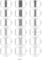
- Figures 4ai, 4aii , 4aiii and 4aiv contain (raw) backscattered signals used to train the machine learning classifier.
- Figure 4b presents a deep learning architecture, in which the input contains 1000 elements, and where there are five fully connected (FC) layers.
- FC1 has 256 neurons, FC2 128 neurons, FC3 64 neurons, FC4 28 neurons and FC5 16 neurons: [256, 128, 64, 32, 16].
- a rectified linear unit (ReLu) activation function may be provided, except before the output, where a sigmoid activation function may be used.
- the output may have dimensionality 1 and can be either 0 (non-contaminated/clean or quality of focus conform) or 1 (contaminated/not clean or quality of focus non-conform).
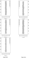
- Figure 4c presents a confusion matrix corresponding to the illustrative machine learning classifier model.
- Figure 4d presents a corresponding receiver operating characteristic (ROC) curve.
- the optical system is configured such that samples to be analysed with such system are provided on the means for providing a sample.
- the optical means of the optical system may thus be exposed to the sample and contaminated, leading to a need of cleaning. Moreover, the continued cleaning may lead to a reduction of the quality of focus of the optical system.
- condition of an optical system may be determined upon providing a sample to be analysed in the means for providing the sample and cleaning the optical system.
- condition of the optical system is determined immediately after it has been used for analysing a sample -thereby potentially contaminated or degraded.
- determining the presence of contamination in the optical system comprises comparing the present signal with the threshold or expected value obtained from the reference signals.
- An example thus consists of determining if the present signal is within or without the threshold.
- a measure of how much the present signal overcomes the threshold Particularly, it may be determined how much of the present signal:
- FIG. 5 several illustrative present signals (backscattering signals, Milli-Q ultrapure water) are represented.
- the dotted lines characterise voltage peak-to-peak represent a higher or upper threshold and a lower threshold automatically defined by the method of the present disclosure and representing the baseline signal.
- VPP voltage peak-to-peak
- the two signals on the right only slightly overcomes the upper threshold, in a measure considered to be low and thus representing an optical system with a conform condition.
- the middle signal and the two signals on the right overcome in several points both the upper and the lower thresholds (regions in lighter grey).
- such measure of how much of a signal overcomes a threshold may be determined as a percentage, particularly:
- the percentage of the present signal that is flagged as outside the thresholds that can be acceptable may also be defined.
- An example may be of a percentage lower than a given number, such as lower than 5%, outside the thresholds.
- the method of the present disclosure, illustrated in Figure 6a , while determining the presence of contamination in the optical system may thus comprise the steps of:
- comparing the present signal with the baseline signal may comprise applying at least one metric to the present signal, thereby extracting at least one feature from the present signal, and comparing such feature extracted from the present signal with the threshold or expected value.
- the metric applied to the present signal is one or more of voltage peak-to-peak, mean, standard deviation, Skewness, Kurtosis and root mean square (RMS).
- Determining the quality of focus of the optical system may comprise obtaining a plurality of present signals from a plurality of corresponding samples and comparing the present signals with the said baseline signal, each of the corresponding samples and the reference samples comprising a clean solvent (e.g., water) and nanoparticles subsequently provided in the means for providing a sample, the water optionally being ultrapure water or Milli-Q ultrapure water.
- a clean solvent e.g., water
- the quality of optical focussing which may include a level of degradation of the optical system due to cleaning (as an example) may be referred to as being analysed based on the total amount of collected light of the backscattering or forward scattering signal.
- the method of the present disclosure may further include obtaining present signals from corresponding present samples, to be compared with the baseline signal, where such corresponding present samples contain not only water or ultrapure water or Milli-Q water, but also nanoparticles in suspension in such clean solvent (e.g., water).
- corresponding present samples contain not only water or ultrapure water or Milli-Q water, but also nanoparticles in suspension in such clean solvent (e.g., water).
- Figure 8 contains six examples of backscattered signals obtained when using NIST (National Institute of Standards and Technology) calibrated Polystyrene nanoparticles (NP) (an illustrative example).
- NIST National Institute of Standards and Technology
- NP Polystyrene nanoparticles
- Backscattering or forward scattering signals according to the present disclosure may have different temporal durations and sampling frequencies.
- 30s of signal together with 50kHz of sampling rate may be applied.
- the calibration of NIST calibrated nanoparticles provides that only the size of the NP is calibrated, not their concentration.
- a set of measurements - obtaining present signals - may thus be performed to determine the quality of focus, based on the same sized nanoparticles in which the calibration sample is diluted by known steps to make the measurements independent of the exact concentration used.
- nanoparticle materials sizes or even mixtures of NP materials and NP sizes during these control measurements may be used.
- the reference samples containing the clean solvent and nanoparticles may consist of an original sample of the clean solvent and nanoparticles and a plurality of dilutions of the original sample in the clean solvent, each dilution having an order corresponding to a lower concentration of nanoparticles as regards the original sample and a prior dilution.
- the current samples containing the clean solvent and nanoparticles may consist of an original sample of clean solvent and nanoparticles and a plurality of dilutions of the original sample in the clean solvent, each dilution having an order corresponding to a lower concentration of nanoparticles as regards the original sample and a prior dilution.
- the clean solvent may be water.
- Water may be ultrapure water or Milli-Q ultrapure water.
- monitoring the optical signal from NPs over time and comparing against the established baseline will enable the monitoring of the degradation of the optical system, thus enabling monitoring of its lifetime.
- the method of the present disclosure thus includes obtaining a plurality of present signals, measurements of backscattered or forward scattered signals, using multiple samples of nanoparticles, for instance synthetic NPs with NIST-traceable size, each of the samples at a different concentration.
- sample concentration is an extremely challenging quantity to assess.
- the method of the present disclosure while determining quality of focus, is insensitive to concentration, by generating a series of sample dilutions from an original batch at a concentration that does not need to be exactly known.
- the comparison of the present signal with the baseline signal may comprise extracting at least one feature from the present signals and comparing such extracted feature or features with the threshold or expected value obtained from the reference signals.
- establishing a baseline signal for such optical system may comprise:
- Each of the samples (including the original, non-diluted, one) are passed through the optical system, and the corresponding backscattered or forward signal may be obtained.
- features - present features - of the present signal can be extracted and a comparison between the obtained metrics - present metrics - with the metrics obtained during the calibration phase of baseline signal establishment of the optical system, and an assessment of the quality of focus of the optical system is provided.
- VPP signal voltage peak-to-peak
- the plot in Figure 10 shows the change of slope vs spot size radius for a total of 3 different batches with different initial concentrations. A single batch could be used.
- This methodology enables to determine the quality of focusing using an ensemble of nanoparticles.
- signal VPP as a feature
- linear regression as a metric to be fit is an illustrative example of the present disclosure.
- the method of the present disclosure refers to the determination of a condition of an optical system.
- An optical system is also an object of the present disclosure, in particular an optical system which comprises the device of the present disclosure, which in turn is configured to implement the method of the present disclosure.
- the optical system may comprise:
- the light emitting means configured to produce illumination consisting of a coherent light beam may be such that the coherent light beam is a laser beam.
- the light acquisition means may comprise the optical means prone to be exposed to a sample to be analysed with the optical system, when the sample is provided in the means for providing a sample.
- the light acquisition means may thus comprise optical means which in turn comprise a focusing element.
- focusing element comprises a fibre optic which acts as a focusing element.
- the fibre optic may be fixedly coupled to the means for providing a sample, and thereby guide a backscattering or forward scattering signal produced upon illumination of the sample towards other elements of the light acquisition means.
- the optical system may include a light emitting means, a fibre optic coupler, a photodetector, and a lensed fibre that is inserted in means for providing a sample which may comprise a sample of interest - such as a fluidic sample of interest.
- the lensed fibre may thus be part of the light acquisition means which may also be referred to as a sample analysis device (SAD).
- a data acquisition board is also included in the setup to digitise the analogue voltages from the photodetector.
- the light emitting means [100] are connected to one input of a 50:50 fibre optic coupler with a 1x2 configuration [101]. Its input is spliced into the optical fibre of the SAD [102] to guide light into the lensed fibre probe and to acquire the backscattered signal from the sample, through a silicon amplified photodetector [103], which is coupled to the second output of the 50:50 fibre optic coupler [101].
- the photodetector is connected to a data acquisition board [104] to acquire the backscattered signal from the SAD and send them to a workstation [105] for analysis.
- a 99:1 fibre optic coupler [106] with a 1x2 configuration can be used to monitor the signal from the light source, through a second photodetector [107] or a conventional lens focused into an optically transparent container or microfluidic channel can be used to form the SAD.
- the laser may be modulated by a modulation frequency, in particular modulated as a function of time, by modulating the optical power.
- the laser may also not be modulated.
- the optical system of the present disclosure may be associated with an apparatus for providing samples into the means for providing a sample in an automated fashion, as depicted in Figure 11 .
- the apparatus may be such that samples are fluidic samples provided in an n-well plate, n being an integer larger than 1, typically equal or larger than 6, 12, 24, 48, 96, 384.
- Each sample may be pumped through a tip of a tube under the action of a first pump and dripped into the means for providing a sample.
- a fibre optic is fixedly provided into the means for providing a sample.
- the plate may further contain cleaning solutions with water, to clean the whole set after a sample has been analysed.
- Figure 12 shows a photography of a lensed fibre, a fibre optic, fixedly coupled to means for providing a sample.
- the machine learning classifier was trained with 5,000 contaminated backscattering signals and 5,000 non-contaminated backscattering signals. Adam was used as an optimiser, the results of 99.8% accuracy, 98% AUROC, 91% sensitivity, 93% specificity were achieved, as shown in Figures 4c and 4d .
- the SAD After each measurement on a sample [200], the SAD is subjected to a cleaning procedure [201], and after, the backscattered signal in Milli-Q water [202] is measured.
- the cleaning procedure was comprised of three steps: first, the SAD is rinsed with distilled water [203]; second, the SAD is rinsed with a neutral detergent solution [204]; and third, the SAD is rinsed with distilled water [205].
- the detergent solution can be left to act over a period of time, and it can be shifted back and forth while acting.
- the cleaning procedure can be repeated an arbitrary number of times (typically 2 but not restricted to that).
- the samples used are contaminating media as well as calibration standards, used to simultaneously evaluate the quality of focussing and to contaminate the SAD prior to cleaning.
- the automated method of the present disclosure may be implemented by an electronic or computational device installed locally or remotely.
- the device of the present disclosure by being configured to implement the method of the present disclosure, thereby comprises an electronic or computational device, being installed locally or remotely.
- the device may include components to perform at least some of the example features and features of the methods described, whether through hardware components (such as memory and / or processor), software or any combination thereof.
- a "computer-readable medium” means any medium that can store instructions for use or execution by a computer or other computing device, including read-only memory (ROM), erasable programmable read-only memory (EPROM) or flash memory, random access memory (RAM), a portable floppy disk, a drive hard drive (HDD), a solid state storage device (for example, NAND flash or synchronous dynamic RAM (SDRAM)), and/or an optical disc such as a Compact Disc (CD), Digital Versatile Disc (DVD) or Blu-Ray TM Disc.
- ROM read-only memory
- EPROM erasable programmable read-only memory
- RAM random access memory
- HDD drive hard drive
- SDRAM synchronous dynamic RAM
- CD Compact Disc
- DVD Digital Versatile Disc
- Blu-Ray TM Disc Blu-Ray TM Disc
Landscapes
- Physics & Mathematics (AREA)
- Health & Medical Sciences (AREA)
- Life Sciences & Earth Sciences (AREA)
- Chemical & Material Sciences (AREA)
- Analytical Chemistry (AREA)
- Biochemistry (AREA)
- General Health & Medical Sciences (AREA)
- General Physics & Mathematics (AREA)
- Immunology (AREA)
- Pathology (AREA)
- Investigating Or Analysing Materials By Optical Means (AREA)
Priority Applications (1)
| Application Number | Priority Date | Filing Date | Title |
|---|---|---|---|
| PCT/IB2024/061601 WO2025109482A1 (en) | 2023-11-20 | 2024-11-20 | An automated method for determining a condition of an optical system |
Applications Claiming Priority (1)
| Application Number | Priority Date | Filing Date | Title |
|---|---|---|---|
| PT11905823 | 2023-11-20 |
Publications (1)
| Publication Number | Publication Date |
|---|---|
| EP4556888A1 true EP4556888A1 (de) | 2025-05-21 |
Family
ID=95477315
Family Applications (1)
| Application Number | Title | Priority Date | Filing Date |
|---|---|---|---|
| EP23220649.0A Withdrawn EP4556888A1 (de) | 2023-11-20 | 2023-12-28 | Ein automatisiertes verfahren zur bestimmung des zustands eines optischen systems |
Country Status (1)
| Country | Link |
|---|---|
| EP (1) | EP4556888A1 (de) |
Citations (4)
| Publication number | Priority date | Publication date | Assignee | Title |
|---|---|---|---|---|
| WO2009094076A2 (en) * | 2008-01-22 | 2009-07-30 | Cummins Filtration Ip Inc. | Pass-fail tool for testing particulate contamination level in a fluid |
| CN102445458A (zh) * | 2011-10-18 | 2012-05-09 | 中国科学院合肥物质科学研究院 | 一种光学透镜测污装置 |
| US20180366570A1 (en) * | 2009-05-01 | 2018-12-20 | Garrett Thermal Systems Limited | Particle detectors |
| WO2023273421A1 (zh) * | 2021-06-30 | 2023-01-05 | 上海禾赛科技有限公司 | 用于激光雷达的光罩脏污检测方法及光罩脏污检测系统 |
-
2023
- 2023-12-28 EP EP23220649.0A patent/EP4556888A1/de not_active Withdrawn
Patent Citations (4)
| Publication number | Priority date | Publication date | Assignee | Title |
|---|---|---|---|---|
| WO2009094076A2 (en) * | 2008-01-22 | 2009-07-30 | Cummins Filtration Ip Inc. | Pass-fail tool for testing particulate contamination level in a fluid |
| US20180366570A1 (en) * | 2009-05-01 | 2018-12-20 | Garrett Thermal Systems Limited | Particle detectors |
| CN102445458A (zh) * | 2011-10-18 | 2012-05-09 | 中国科学院合肥物质科学研究院 | 一种光学透镜测污装置 |
| WO2023273421A1 (zh) * | 2021-06-30 | 2023-01-05 | 上海禾赛科技有限公司 | 用于激光雷达的光罩脏污检测方法及光罩脏污检测系统 |
Similar Documents
| Publication | Publication Date | Title |
|---|---|---|
| JP2013531787A (ja) | 粒子の運動度および/または細胞の分散を求めるためのホログラフィック変動顕微鏡装置および方法 | |
| EP4047364A1 (de) | System und verfahren zur messung von wassereigenschaften in einer wasseranlage | |
| WO2020012528A1 (ja) | 光分析装置、光分析方法および学習済みモデル | |
| EP4556888A1 (de) | Ein automatisiertes verfahren zur bestimmung des zustands eines optischen systems | |
| WO2025015171A2 (en) | Automated spectroscopic analysis of micron-scale microplastic particles with optical photothermal infrared spectroscopy | |
| EP3786611A1 (de) | Vorrichtung zur messung der partikelgrössenverteilung und programm für vorrichtung zur messung der partikelgrössenverteilung | |
| WO2023095414A1 (ja) | 微小粒子の計測方法、微小粒子計測装置及び微小粒子計測システム | |
| WO2025109482A1 (en) | An automated method for determining a condition of an optical system | |
| JP4359769B2 (ja) | センサの汚れ検出方法 | |
| JP5883233B2 (ja) | 走査型顕微光散乱測定解析装置および光散乱解析方法 | |
| KR102436336B1 (ko) | 인공지능 기반의 미세조류 검출장치 및 그 방법 | |
| De Zanet et al. | Impedance biosensor for real-time monitoring and prediction of thrombotic individual profile in flowing blood | |
| KR101878909B1 (ko) | 라만 신호와 위상변화를 동시에 측정하는 시스템 및 그 방법 | |
| CN120677225A (zh) | 异物及粒子的凝集体的检查装置及检查方法 | |
| WO2021181482A1 (ja) | 顕微鏡画像撮像方法および顕微鏡画像撮像装置 | |
| KR20200044172A (ko) | 표면검사를 위한 딥러닝 학습방법 | |
| WO2019055151A1 (en) | OPTICAL ANALYSIS OF WELLBORE WELL FLUID DEEMULTIVATORS | |
| JP2006275771A (ja) | 細胞画像解析装置 | |
| Paiva et al. | Towards a single parameter sensing for bacteria sorting through optical fiber trapping and back-scattered signal analysis | |
| JP2017096872A (ja) | 分析方法および分析装置 | |
| KR20200096564A (ko) | 유체 내에서 미시적 물체 검출 | |
| KR102907991B1 (ko) | 광학 기술을 이용한 기생충란 검출 방법 및 장치 | |
| CN119167179B (zh) | 一种水中悬浮颗粒结构快速感知方法、系统与装置 | |
| Godefroy et al. | Automated Viability Estimation from Digital Holographic Microscopy: Validation on Heterogeneous Industrial Bioproduction Cultures | |
| US20230393117A1 (en) | Biological information measurement device, biological information measurement method, and computer-readable recording medium |
Legal Events
| Date | Code | Title | Description |
|---|---|---|---|
| PUAI | Public reference made under article 153(3) epc to a published international application that has entered the european phase |
Free format text: ORIGINAL CODE: 0009012 |
|
| STAA | Information on the status of an ep patent application or granted ep patent |
Free format text: STATUS: THE APPLICATION HAS BEEN PUBLISHED |
|
| AK | Designated contracting states |
Kind code of ref document: A1 Designated state(s): AL AT BE BG CH CY CZ DE DK EE ES FI FR GB GR HR HU IE IS IT LI LT LU LV MC ME MK MT NL NO PL PT RO RS SE SI SK SM TR |
|
| STAA | Information on the status of an ep patent application or granted ep patent |
Free format text: STATUS: THE APPLICATION IS DEEMED TO BE WITHDRAWN |
|
| 18D | Application deemed to be withdrawn |
Effective date: 20251122 |