EP4556988A2 - Combinateur optique plat ayant un miroir asphérique hors axe intégré pour des viseurs réflex compacts - Google Patents
Combinateur optique plat ayant un miroir asphérique hors axe intégré pour des viseurs réflex compacts Download PDFInfo
- Publication number
- EP4556988A2 EP4556988A2 EP25168951.9A EP25168951A EP4556988A2 EP 4556988 A2 EP4556988 A2 EP 4556988A2 EP 25168951 A EP25168951 A EP 25168951A EP 4556988 A2 EP4556988 A2 EP 4556988A2
- Authority
- EP
- European Patent Office
- Prior art keywords
- curvature
- aspheric
- optical
- aspherical
- optical element
- Prior art date
- Legal status (The legal status is an assumption and is not a legal conclusion. Google has not performed a legal analysis and makes no representation as to the accuracy of the status listed.)
- Pending
Links
Images
Classifications
-
- F—MECHANICAL ENGINEERING; LIGHTING; HEATING; WEAPONS; BLASTING
- F41—WEAPONS
- F41G—WEAPON SIGHTS; AIMING
- F41G1/00—Sighting devices
- F41G1/30—Reflecting-sights specially adapted for smallarms or ordnance
-
- G—PHYSICS
- G02—OPTICS
- G02B—OPTICAL ELEMENTS, SYSTEMS OR APPARATUS
- G02B23/00—Telescopes, e.g. binoculars; Periscopes; Instruments for viewing the inside of hollow bodies; Viewfinders; Optical aiming or sighting devices
- G02B23/02—Telescopes, e.g. binoculars; Periscopes; Instruments for viewing the inside of hollow bodies; Viewfinders; Optical aiming or sighting devices involving prisms or mirrors
- G02B23/10—Telescopes, e.g. binoculars; Periscopes; Instruments for viewing the inside of hollow bodies; Viewfinders; Optical aiming or sighting devices involving prisms or mirrors reflecting into the field of view additional indications, e.g. from collimator
- G02B23/105—Sighting devices with light source and collimating reflector
-
- G—PHYSICS
- G02—OPTICS
- G02B—OPTICAL ELEMENTS, SYSTEMS OR APPARATUS
- G02B23/00—Telescopes, e.g. binoculars; Periscopes; Instruments for viewing the inside of hollow bodies; Viewfinders; Optical aiming or sighting devices
- G02B23/14—Viewfinders
-
- G—PHYSICS
- G02—OPTICS
- G02B—OPTICAL ELEMENTS, SYSTEMS OR APPARATUS
- G02B27/00—Optical systems or apparatus not provided for by any of the groups G02B1/00 - G02B26/00, G02B30/00
- G02B27/10—Beam splitting or combining systems
- G02B27/14—Beam splitting or combining systems operating by reflection only
- G02B27/141—Beam splitting or combining systems operating by reflection only using dichroic mirrors
-
- G—PHYSICS
- G02—OPTICS
- G02B—OPTICAL ELEMENTS, SYSTEMS OR APPARATUS
- G02B27/00—Optical systems or apparatus not provided for by any of the groups G02B1/00 - G02B26/00, G02B30/00
- G02B27/0025—Optical systems or apparatus not provided for by any of the groups G02B1/00 - G02B26/00, G02B30/00 for optical correction, e.g. distorsion, aberration
Definitions
- Optical combiners combine two optical signals into one.
- At least one application of an optical combiner includes reflex gun sights.
- a reflex gun sight allows a user to see an intended target through the combiner while simultaneously seeing a reflex image (an at least partial reflection) of a light source.
- the reflex image of the light source is intended to align with a nominal trajectory of a projectile.
- the optical combiner combines the view of the target (e.g., in the far field) with a collimated reflection of the light source.
- the light source reflection e.g., a red dot
- Optical combiners described herein provide a collimated beam from a light source that generates an aiming reference (e.g., a "red dot"), while simultaneously allowing undistorted observation of a target.
- the "red dot” is viewed by a user, as a portion of the collimated light sampled by the pupil of the user's eye and focused on the user's retina.
- optical combiners described herein may have a flat (planar) front, aligned with (e.g., perpendicular to) an axis of rotational symmetry of a curved reflective surface.
- optical combiners as described herein minimize aberrations (including distortion) of the target image that might otherwise be caused by an angle or tilting of a curved optical combiner.
- optical combiners described herein may include an aspherical reflective surface to provide improved collimation, and therefore accuracy, of the "red dot" aiming reference.
- optical combiners described herein may include reflective surfaces whose axis of rotational symmetry is off-set from the user's line of sight and/or from the structure of the optical combiner itself, including examples where the vertex of the reflective curvature is not part of the optical combiner, e.g., the vertex lies outside the structural bounds of the optical combiner.
- an optical combiner includes a first optical element having a convex surface, a second optical element having a concave surface, at least one of the convex surface or the concave surface having an aspherical curvature, a reflective coating applied to the at least one of the convex surface or the concave surface having an aspherical curvature, and an adhesive arranged to couple the convex surface to the concave surface to provide a combined optical element including the first optical element and the second optical element as an optical doublet.
- the aspherical curvature has an axis of rotational symmetry (also sometimes referred as an axis of curvature herein) substantially normal to a planar surface of at least one of the first optical element and the second optical element.
- the aspherical curvature has a vertex that is not located on the convex surface and not located on the concave surface.
- the first and second optical elements include a planar surface nominally orthogonal to an axis of curvature (e.g., an axis of rotational symmetry) of the aspherical curvature.
- the aspherical curvature is defined at least in part by a conic constant of zero.
- the aspherical curvature is defined at least in part by a non-zero higher order coefficient.
- the aspherical curvature is defined at least in part by a non-zero fourth order coefficient, such that an aspheric departure varies with the fourth power of a linear distance from a vertex. In certain embodiments, the aspherical curvature is defined at least in part by a non-zero sixth order coefficient, such that an aspheric departure varies with the sixth power of the linear distance from the vertex.
- Some embodiments include a light source nominally positioned at a focal point of the aspherical curvature.
- the reflective coating is a dichroic reflective coating.
- the convex surface has the aspherical curvature and the concave surface has a spherical curvature.
- the reflective coating is configured to reflect a waveband within a visible spectrum.
- each of the first and second optical elements are transmissive of a range of wavelengths in the visible spectrum, the range of wavelengths broader than and including the waveband.
- Certain embodiments also include a light source nominally positioned at a focal point of the aspherical curvature, the light source configured to generate light at a wavelength within the waveband.
- a reflex sighting device having a line of sight for a user to view a target.
- the sighting device includes an optical element having substantially flat front and rear surfaces, the front and rear surfaces positioned substantially orthogonal to the line of sight, an aspheric reflective surface embedded in the optical element and positioned to reflect and collimate light originating at a focal point, such that the collimated light emerges from the optical element substantially orthogonal to the front and rear surfaces and substantially parallel to the line of sight, and a light source nominally positioned at the focal point and configured to generate light directed at the reflective surface.
- the aspheric reflective surface includes a dichroic mirror coating.
- the aspheric reflective surface follows a curvature defined at least in part by a conic constant of zero.
- the aspheric reflective surface follows a curvature defined at least in part by a non-zero higher order coefficient.
- the aspheric reflective surface follows a curvature defined at least in part by a non-zero fourth order coefficient, such that an aspheric departure varies with the fourth power of a linear distance from a vertex.
- the aspheric reflective surface follows a curvature also defined at least in part by a non-zero sixth order coefficient, such that an aspheric departure varies with the sixth power of the linear distance from the vertex.
- the reflective surface is a dichroic reflective surface.
- the reflective surface is configured to reflect a waveband within a visible spectrum.
- the light source is configured to generate the light including a wavelength within the waveband.
- a method of calibrating a reflex sight having an optical combiner with a reflective curvature includes directing collimated light at a planar surface of the optical combiner, aligning the collimated light to be substantially normal to the planar surface, detecting a portion of the collimated light reflected by the reflective curvature, translating the collimated light through a range of positions while substantially maintaining alignment of the collimated light substantially normal to the planar surface, detecting a location where the portion of the collimated light reflected by the reflective curvature remains substantially fixed while translating the collimated light, and placing a light source at the location.
- aligning the collimated light to be substantially normal to the planar surface includes detecting a portion of the collimated light that is reflected by the planar surface.
- Certain embodiments include orienting the light source such that the light source directs light toward the reflective curvature when placed in operation.
- Some embodiments include mounting the reflex sight. Certain embodiments include mounting the reflex sight to a firearm.
- Various embodiments include mounting the reflex sight to one of a weapon, a camera, a telescope, a lens, a gimbal, a vehicle, a communication device, a transceiver, and an antenna.
- Various aspects and embodiments are directed to improved systems and methods for optical combiners that may be advantageously applied in reflex gun sights and other visual aiming or targeting applications.
- references to "or” may be construed as inclusive so that any terms described using “or” may indicate any of a single, more than one, and all of the described terms. Any references to front and back, left and right, top and bottom, upper and lower, end, side, vertical and horizontal, and the like, are intended for convenience of description, not to limit the present systems and methods or their components to any one positional or spatial orientation.
- Conventional reflex sights include optical combiners with curved surfaces which customarily cause distortion of imagery.
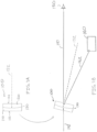
- FIG. 1A there is illustrated an example of a conventional optical combiner 100 of rare form, having a front planar surface 112 of a front optical element 110 and a rear planar surface 122 of a rear optical element 120.
- the front optical element 110 and the rear optical element 120 are matched or joined together at a curved surface 130.
- the curved surface 130 is embedded in the conventional optical combiner 100 and is at least partially reflective and at least partially transmissive, as discussed in more detail below.
- An axis of symmetry 132 of the curved surface 130 is also shown.
- the curved surface 130 conventionally conforms to a spherical shape or a parabolic shape, and therefore may include a focal point on the axis of symmetry.
- FIG. 1B illustrates the conventional optical combiner 100 used as a component of a reflex sight.
- the conventional optical combiner 100 is tilted at an angle relative to a line of sight 140, and light 142 entering the optical combiner 100 from a target (not shown) is allowed to pass through the optical combiner 100 and follow the line of sight 140 and be viewed by a user 150.
- a "red dot" image is superimposed on the scene viewed by the user 150 by action of the curved surface 130 reflecting light from a light source 160.
- the term “red dot” is merely a notional term, and the light source 160 may be configured to provide any of various colors of light (e.g., green) and may include any of various shapes (e.g., cross-hair).
- the light source 160 produces light 162 that enters the optical combiner 100 through the rear optical element 120 and is reflected (at least partially) by the curved surface 130.
- the curved surface 130 approximately collimates the light 162 so that a small image of the light 162 (e.g., a red dot) may appear substantially fixed on the scene, as viewed by the user 150, for a range of viewing positions of the user's eye.
- the spherical or parabolic shape of the curved surface 130 provides only limited ability to provide collimated light, thus limiting the range of viewing angles and/or reducing accuracy of position of the "red dot.”
- aspects and embodiments described herein provide an off-axis aspherical reflective surface to solve the above problem of a flat refractive surface, resulting in very fast collimator optics.
- a parent mirror clear aperture diameter is 34 mm
- a focal length of the collimator is 30 mm, such that a corresponding f-number is (30/34) - which is less than one!
- combiners having flat refractive surfaces, in accord with aspects and embodiments described herein are much easier to handle during large scale production than those having curved surfaces, are easier to seal, and are more readily made to withstand underwater pressure at varying and significant depths.
- aspects and embodiments disclosed herein provide optical combiners with improved collimation of the reflected light, and planar surfaces substantially normal to the line of sight, each of which provide for higher accuracy across a wider range of viewing angles, without optical distortion.
- Optical combiners and methods in accord with aspects and embodiments disclosed herein also accommodate relative ease of manufacture and calibration, such as final placement of a light source.
- the term "aspherical curvature” generally refers to a curved aspherical surface.
- axis of curvature refers generally to an axis of symmetry of the aspherical surface, as opposed to an axis at an individual local point on the surface. Accordingly, the term “axis of curvature” as used herein may refer to an axis defined by, or at, a vertex point of a curved aspherical surface.
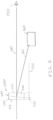
- FIG. 2 illustrates a reflex sight arrangement including an example of an optical combiner 200 in accord with aspects and embodiments described herein.
- the optical combiner 200 includes a front optical element 210 joined with a rear optical element 220 and having an internally embedded aspheric mirror 230.
- the front optical element 210 has a planar surface 212 that may be positioned substantially normal to the line of sight 140 of the user 150
- the rear optical element 220 has a planar surface 222 that may also be positioned substantially normal to the line of sight 140.
- the aspheric mirror 230 has an axis of curvature 232 that is substantially parallel to the line of sight 140.
- a vertex 234, which is the point of intersection between the curved surface of the aspheric mirror 230 and the axis of curvature 232, is an imaginary point that lies outside the optical combiner 200.
- the aspheric mirror 230 may be formed as a rotationally symmetric aspherical surface, e.g., formed of an interior surface on either of the front optical element 210 or the rear optical element 220, and coated with a dichroic mirror coating.
- the aspheric mirror 230 may have a higher-order aspherical curvature, as discussed in more detail below, in various embodiments.
- the dichroic mirror coating reflects light of a narrow band of wavelengths, and is matched to be reflective of the light source 160, e.g., red, green, or other light.
- an aspherical curvature may be selected for the aspheric mirror 230, including higher-order aspheric coefficients in some embodiments, to provide accurate collimation of light 162 (from the light source 160) into the line of sight 140.
- Accuracy of the collimation of the light 162 is further enhanced by aspects and embodiments disclosed herein by virtue of the vertex 234 being off the line of sight 140, such that the axis of curvature 232 may be substantially parallel with the line of sight 140, and placement of the light source 160 may be substantially in line with the vertex 234 and on the axis of curvature 232.
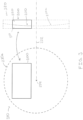
- FIG. 3 shows a schematic front view 310 and a schematic side view 320 illustrating at least one form of the optical combiner 200.
- the aspheric mirror 230 follows a curvature 230a as shown in some detail in FIG. 3 .
- the front and rear optical elements 210, 220 may be formed of an optical material having various desirable properties, such as optical clarity, hardness, refractive index, etc.
- the curvature 230a, a portion of which forms part of the aspheric mirror 230, may be formed as an aspherical convex surface of the rear optical element 220 in various embodiments, and the front optical element 210 may have a spherical concave surface selected to be a close match to the aspherical convex surface.
- the front and rear optical elements 210, 220 may be joined together at their curved surfaces with an optical cement that matches the refractive index(es) of the front and rear optical elements 210, 220.
- the spherical concave surface may be a best fitting sphere to the aspherical convex surface.
- the curvature 230a may be formed as an aspherical concave surface on the front optical element 210, or may be formed as adjoining aspherical surfaces on each of the front and rear optical elements 210, 220.
- optical combiner 200 is shown in the front view 310 of FIG. 3 as having a rectangular profile when viewed from the front or rear, various embodiments may have other shapes or forms.
- various optical combiners in accord with aspects and embodiments described herein may be square, circular, oblong, or other shapes having linear or rounded edges, and may or may not be symmetrical.
- the curvature 230a is an aspherical curvature (a curved aspherical surface), and at least a portion of the curvature 230a forms a surface that becomes the aspheric mirror 230 by application of a reflective coating, e.g., a dichroic mirror coating.
- the curvature 230a may be defined by equation (1), which gives the sag, z, defining the departure of the curvature 230a, from a planar reference, at a radial distance, r, from the vertex along the plane.
- the curvature 230a is rotationally symmetric about the axis of curvature 232, and centered on the vertex 234.
- z cr 2 1 + 1 ⁇ 1 + k c 2 r 2 + Ar 4 + Br 6 + Cr 8 + Dr 10 + Er 12 + Fr 14 + ⁇
- the higher order coefficients, A, B, C, D, E, F, ... may be referred to as aspheric deformation coefficients.
- the curvature, c is the inverse of the vertex radius of curvature.
- the curvature 230a is defined by equation (1) having a non-zero value for at least one of the constants, k, A, B, C, ..., etc. to have an aspherical shape.
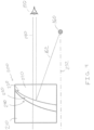
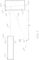
- FIG. 4 illustrates one example of an assembly of the optical combiner 200.
- the aspheric mirror 230 may be formed on the rear optical element 220 as an aspheric curvature (e.g., a portion of the curvature 230a of FIG. 3 ) with a dichroic reflective surface coating (e.g., to reflect the light 162).
- the front optical element 210 may have a spherical surface 240 selected to match well to the shape of the aspheric mirror 230. For example, a spherical surface 240 that minimizes the volume of a gap 250 between it and the aspheric mirror 230 may be considered a best fitting sphere.
- the gap 250 which is exaggerated in the figure for clarity, may be filled with an index-matching optical cement, thereby joining the front and rear optical elements 210, 220 to each other and filling the gap 250 so that the optical combiner 200 exists as a solid unit.
- the spherical surface 240 may be more easily manufactured than the curvature of the aspheric mirror 230, and the assembly illustrated in FIG. 4 therefore allows the optical combiner 200 to be manufactured requiring only a single aspherically curved surface to be created.
- the optical combiner 200 may have a prescription as annotated in Table 1, which is provided merely for illustrative purposes of at least one example of an optical combiner in accord with aspects and embodiments described herein.
- Table 1 Various dimensions and values noted in Table 1 may be approximate, and various other embodiments may have dimensions and values vastly different from those in Table 1.
- FIG. 5 illustrates one example of a method of aligning a light source 160 to the optical combiner 200.
- a collimated light source 510 (which may emit a white light, for example) may be positioned to emit light 512 at the planar surface 222 of the rear optical element 220.
- the collimated light source 510 (an autocollimator in some examples) may be precisely positioned so that the light 512 travels substantially parallel to what will be the line of sight, because a small amount of reflected light 514 may be reflected by the planar surface 222, which as discussed above is substantially normal to the line of sight.
- the reflected light 514 aligns with an optical axis of the collimated light source 510, it may be confirmed that the light 512 is travelling normal to the planar surface 222, and therefore parallel with the intended line of sight.
- the aspheric mirror 230 reflects a reflex light 516, which is a narrow waveband portion of the light 512 (e.g., red light, depending upon the dichroic coating) that passes through a focal point 518.
- Translational movement 520 of the collimated light source 510 without alteration to its orientation (e.g., maintaining the path of the light 512 to be parallel to the line of sight), produces a range of reflex light 516 that all pass through the focal point 518, thereby allowing easy identification of the focal point 518.
- the aspheric mirror may provide better collimation of light, allowing a larger area of the optical combiner to provide precise and accurate positioning of the "red dot" across a range of viewing positions. Accordingly, such may allow a larger eyebox for the user to look through, and allow the user's eye position to be more widely off-center while maintaining accuracy of aiming.
- Positioning of the aspheric mirror such that the vertex of the curvature of the aspheric mirror is out of the line of sight, and such that the axis of curvature of the aspheric mirror is substantially parallel to the line of sight, allows placement of the light source at the focal point, which also improves the collimation accuracy, again providing more precise and accurate aiming with the "red dot.”
- Planar front and rear surfaces of the optical combiner provide no distortion and, accordingly, improved accuracy.
- the planar rear surface may be advantageously used for alignment and calibration, to confirm alignment of a collimated light source that allows identification of a focal point.
- Various embodiments may be more easily manufactured, requiring only one aspherical surface to be fabricated, by joining the mirror-coated aspherical surface to a well-fitting spherical surface, with optical cement, to form a single unit thereby having an interior aspherical mirror.
Landscapes
- Physics & Mathematics (AREA)
- Optics & Photonics (AREA)
- General Physics & Mathematics (AREA)
- Astronomy & Astrophysics (AREA)
- Engineering & Computer Science (AREA)
- General Engineering & Computer Science (AREA)
- Lenses (AREA)
- Optical Elements Other Than Lenses (AREA)
Applications Claiming Priority (3)
| Application Number | Priority Date | Filing Date | Title |
|---|---|---|---|
| US201862619209P | 2018-01-19 | 2018-01-19 | |
| PCT/CA2018/000074 WO2019140502A1 (fr) | 2018-01-19 | 2018-04-19 | Combinateur optique plat ayant un miroir asphérique hors axe intégré pour des viseurs réflex compacts |
| EP18901063.0A EP3698204A4 (fr) | 2018-01-19 | 2018-04-19 | Combinateur optique plat ayant un miroir asphérique hors axe intégré pour des viseurs réflex compacts |
Related Parent Applications (1)
| Application Number | Title | Priority Date | Filing Date |
|---|---|---|---|
| EP18901063.0A Division EP3698204A4 (fr) | 2018-01-19 | 2018-04-19 | Combinateur optique plat ayant un miroir asphérique hors axe intégré pour des viseurs réflex compacts |
Publications (2)
| Publication Number | Publication Date |
|---|---|
| EP4556988A2 true EP4556988A2 (fr) | 2025-05-21 |
| EP4556988A3 EP4556988A3 (fr) | 2025-10-22 |
Family
ID=71658937
Family Applications (2)
| Application Number | Title | Priority Date | Filing Date |
|---|---|---|---|
| EP25168951.9A Pending EP4556988A3 (fr) | 2018-01-19 | 2018-04-19 | Combinateur optique plat ayant un miroir asphérique hors axe intégré pour des viseurs réflex compacts |
| EP18901063.0A Withdrawn EP3698204A4 (fr) | 2018-01-19 | 2018-04-19 | Combinateur optique plat ayant un miroir asphérique hors axe intégré pour des viseurs réflex compacts |
Family Applications After (1)
| Application Number | Title | Priority Date | Filing Date |
|---|---|---|---|
| EP18901063.0A Withdrawn EP3698204A4 (fr) | 2018-01-19 | 2018-04-19 | Combinateur optique plat ayant un miroir asphérique hors axe intégré pour des viseurs réflex compacts |
Country Status (1)
| Country | Link |
|---|---|
| EP (2) | EP4556988A3 (fr) |
Family Cites Families (10)
| Publication number | Priority date | Publication date | Assignee | Title |
|---|---|---|---|---|
| SE388479B (sv) * | 1973-07-19 | 1976-10-04 | Aga Ab | Optiskt riktmedel |
| GB8714203D0 (en) * | 1987-06-17 | 1987-11-18 | Gec Avionics | Gun sights |
| DE4336962A1 (de) * | 1993-10-29 | 1995-05-04 | Hensoldt & Soehne Optik | Visiervorrichtung |
| GB2292465A (en) * | 1994-03-02 | 1996-02-21 | Clive Rawlinson Paige | Optical sight with part-reflective aspheric surface and mount |
| US5771124A (en) * | 1996-07-02 | 1998-06-23 | Siliscape | Compact display system with two stage magnification and immersed beam splitter |
| JP2001033729A (ja) * | 1999-07-26 | 2001-02-09 | Olympus Optical Co Ltd | 観察光学系 |
| JPWO2007055143A1 (ja) * | 2005-11-08 | 2009-04-30 | 株式会社 ニコンビジョン | 照準器 |
| KR100934778B1 (ko) * | 2006-12-28 | 2009-12-31 | 정인 | 대구경 도트 사이트 조준경 |
| WO2014080406A1 (fr) * | 2012-11-25 | 2014-05-30 | Accutact Llc. | Système de visée panoramique |
| WO2015142654A1 (fr) * | 2014-03-18 | 2015-09-24 | 3M Innovative Properties Company | Combineur d'image à faible profil pour dispositifs d'affichage proches de l'œil |
-
2018
- 2018-04-19 EP EP25168951.9A patent/EP4556988A3/fr active Pending
- 2018-04-19 EP EP18901063.0A patent/EP3698204A4/fr not_active Withdrawn
Also Published As
| Publication number | Publication date |
|---|---|
| EP4556988A3 (fr) | 2025-10-22 |
| EP3698204A4 (fr) | 2021-10-27 |
| EP3698204A1 (fr) | 2020-08-26 |
Similar Documents
| Publication | Publication Date | Title |
|---|---|---|
| EP2634616A1 (fr) | Unité de réticule, appareil optique, et lunette viseur | |
| EP3688509B1 (fr) | Système de visée optique intégré | |
| KR101345028B1 (ko) | 디스플레이형 광학식 조준경 | |
| US10371950B2 (en) | Imaging optical unit for generating a virtual image and smartglasses | |
| EP2592458A1 (fr) | Système optique afocal à réflexion totale dérivée avec un miroir d'orientation de faisceau façonné asphérique | |
| JP3362958B2 (ja) | 視差のない照準器の光学素子 | |
| AU2018402566B2 (en) | Flat optical combiner with embedded off-axis aspheric mirror for compact reflex sights | |
| EP3942350B1 (fr) | Agencement optique pour un affichage | |
| US20220179217A1 (en) | Optical arrangement for a display | |
| US20010048561A1 (en) | Virtual imaging system for small font text | |
| US7100319B2 (en) | Prismatic boresighter | |
| EP4556988A2 (fr) | Combinateur optique plat ayant un miroir asphérique hors axe intégré pour des viseurs réflex compacts | |
| KR102449588B1 (ko) | 2개의 조준점을 갖는 조준경 | |
| CA3083549C (fr) | Combinateur optique plat ayant un miroir aspherique hors axe integre pour des viseurs reflex compacts | |
| CN220820361U (zh) | 融合红点瞄准系统 | |
| KR101440057B1 (ko) | 주야조준경 체계용 분리형 도트 사이트 | |
| KR102544150B1 (ko) | 시역 확장을 위한 프리즘 접합형 도파관 디스플레이 구조체 및 방법 | |
| US11543209B2 (en) | Sighting arrangement comprising a prism system with a flat top surface | |
| US20250116876A1 (en) | Optical element with 3d gradient refractive index | |
| JP2018063384A (ja) | ドットサイト | |
| CN116794824A (zh) | 融合红点瞄准系统 | |
| CN111308590A (zh) | 棱镜、光学模组和光学系统 | |
| JPS6324214A (ja) | 光学装置 | |
| JP2018180270A (ja) | ドットサイト |
Legal Events
| Date | Code | Title | Description |
|---|---|---|---|
| PUAI | Public reference made under article 153(3) epc to a published international application that has entered the european phase |
Free format text: ORIGINAL CODE: 0009012 |
|
| STAA | Information on the status of an ep patent application or granted ep patent |
Free format text: STATUS: REQUEST FOR EXAMINATION WAS MADE |
|
| 17P | Request for examination filed |
Effective date: 20250407 |
|
| AC | Divisional application: reference to earlier application |
Ref document number: 3698204 Country of ref document: EP Kind code of ref document: P |
|
| AK | Designated contracting states |
Kind code of ref document: A2 Designated state(s): AL AT BE BG CH CY CZ DE DK EE ES FI FR GB GR HR HU IE IS IT LI LT LU LV MC MK MT NL NO PL PT RO RS SE SI SK SM TR |
|
| REG | Reference to a national code |
Ref country code: DE Ref legal event code: R079 Free format text: PREVIOUS MAIN CLASS: G02B0027140000 Ipc: F41G0001300000 |
|
| RIC1 | Information provided on ipc code assigned before grant |
Ipc: F41G 1/30 20060101AFI20250624BHEP Ipc: G02B 17/00 20060101ALI20250624BHEP Ipc: G02B 23/10 20060101ALI20250624BHEP Ipc: G02B 23/24 20060101ALI20250624BHEP Ipc: G02B 27/10 20060101ALI20250624BHEP Ipc: G02B 27/14 20060101ALI20250624BHEP Ipc: G02B 17/04 20060101ALI20250624BHEP Ipc: G02B 27/00 20060101ALI20250624BHEP |
|
| PUAL | Search report despatched |
Free format text: ORIGINAL CODE: 0009013 |
|
| AK | Designated contracting states |
Kind code of ref document: A3 Designated state(s): AL AT BE BG CH CY CZ DE DK EE ES FI FR GB GR HR HU IE IS IT LI LT LU LV MC MK MT NL NO PL PT RO RS SE SI SK SM TR |
|
| RIC1 | Information provided on ipc code assigned before grant |
Ipc: F41G 1/30 20060101AFI20250917BHEP Ipc: G02B 17/00 20060101ALI20250917BHEP Ipc: G02B 23/10 20060101ALI20250917BHEP Ipc: G02B 23/24 20060101ALI20250917BHEP Ipc: G02B 27/10 20060101ALI20250917BHEP Ipc: G02B 27/14 20060101ALI20250917BHEP Ipc: G02B 17/04 20060101ALI20250917BHEP Ipc: G02B 27/00 20060101ALI20250917BHEP |