EP4557014A1 - Uhrmechanismus mit einem dreheinstellsystem und uhr mit solch einem mechanismus - Google Patents
Uhrmechanismus mit einem dreheinstellsystem und uhr mit solch einem mechanismus Download PDFInfo
- Publication number
- EP4557014A1 EP4557014A1 EP23209909.3A EP23209909A EP4557014A1 EP 4557014 A1 EP4557014 A1 EP 4557014A1 EP 23209909 A EP23209909 A EP 23209909A EP 4557014 A1 EP4557014 A1 EP 4557014A1
- Authority
- EP
- European Patent Office
- Prior art keywords
- drive
- mobile
- drive device
- configuration
- rotating
- Prior art date
- Legal status (The legal status is an assumption and is not a legal conclusion. Google has not performed a legal analysis and makes no representation as to the accuracy of the status listed.)
- Pending
Links
Images






Classifications
-
- G—PHYSICS
- G04—HOROLOGY
- G04B—MECHANICALLY-DRIVEN CLOCKS OR WATCHES; MECHANICAL PARTS OF CLOCKS OR WATCHES IN GENERAL; TIME PIECES USING THE POSITION OF THE SUN, MOON OR STARS
- G04B17/00—Mechanisms for stabilising frequency
- G04B17/20—Compensation of mechanisms for stabilising frequency
- G04B17/28—Compensation of mechanisms for stabilising frequency for the effect of imbalance of the weights, e.g. tourbillon
- G04B17/285—Tourbillons or carrousels
Definitions
- the present invention relates generally to the field of watchmaking and more particularly concerns a watch mechanism comprising a rotating regulating system, in particular of the tourbillon or carousel type, which watch mechanism is in particular intended to equip a timepiece, such as a wristwatch.
- Watch mechanisms comprising one or more rotating regulating systems are well known in the state of the art.
- “tourbillons” which are characterized by the presence of a fixed wheel (usually called a fixed seconds wheel) with which the escapement pinion meshes, which is carried, with the regulating organ, on the rotating cage of the tourbillon which is itself connected to the barrel through a single gear train
- “carousels” which are characterized in particular by the fact that the seconds wheel (also sometimes called a “false seconds wheel”) is not fixed, but is part of a drive wheel kinematically linked to the escapement which is carried, with the regulating organ, by the rotating cage of the carousel.
- the regulating system is linked to the barrel through two gear trains. The first train provides the energy needed to operate the escapement, while the second train drives the rotating carousel cage.
- the rotating regulating system can in this case be likened to a differential where the escape wheel acts as a kind of satellite.
- the balance is modified so that its frequency is reduced by approximately 2% to take into account the differential in rotational speed between the rotating cage and the seconds wheel, leading to the need to use a specific balance.
- Modified versions of this carousel have been explored in the state of the art (see in particular “Comparative study between the Breguet tourbillon and the carousel of the Danish Bonniksen”, P. Augereau, 6th European Congress of Chronometry (CEC), Bienne, October 17-18, 1996, Session J, Historical Watchmaking, Communication 37, pages 179-182 ).
- European patent No. EP 1 995 650 B1 the contents of which are incorporated herein by reference in their entirety, describes a clockwork movement comprising a carousel whose particularity lies in the fact that the rotating cage makes one complete revolution per minute, while the drive wheel (or “false second wheel") kinematically linked to the escapement is driven by the finishing gear train at a different rotation speed.
- the false seconds wheel set is rotated in the same direction as the rotating cage at a rotation speed twice as high, namely at a rate of two revolutions per minute. It can therefore be deduced that, in this example, the rotation speed of the false seconds wheel set relative to the rotating cage is one revolution per minute.
- European patent No. EP 3 193 216 B1 the contents of which are incorporated herein by reference in their entirety, describes a clock mechanism with a rotating regulating system, the particularity of which lies in the fact that the rotating regulating system is capable of operating in a first operating mode where the rotating cage of the rotating regulating system is driven in rotation and in a second operating mode where the rotating cage is immobilized while ensuring continuity of operation of the escapement and the regulating organ.
- European patent No. EP 3 193 216 B1 the contents of which are incorporated herein by reference in their entirety, describes a clock mechanism with a rotating regulating system, the particularity of which lies in the fact that the rotating regulating system is capable of operating in a first operating mode where the rotating cage of the rotating regulating system is driven in rotation and in a second operating mode where the rotating cage is immobilized while ensuring continuity of operation of the escapement and the regulating organ.
- EP 3 193 216 B1 describes more specifically a solution based on the use of two alternately driven gear trains, in this case a first finishing gear train kinematically linked to the rotating cage and a second finishing gear train kinematically linked to a drive wheel which is arranged to directly or indirectly drive the escapement.
- a selection device is provided in order to select between at least a first operating mode where the first gear train is driven and the second gear train is stopped (causing rotation of the rotating cage and immobilization of the drive wheel, allowing the rotating regulating system to operate like a conventional tourbillon) and a second operating mode where the second gear train is driven and the first gear train is stopped (causing the rotating cage to stop and the drive wheel to rotate, allowing the regulating system to operate like a conventional escapement system).
- the drive wheel forms an outer ring of a double three-ring bearing, the inner ring of which is integral with the rotating cage and a second pinion kinematically linked to the first going train.
- the intermediate ring of the bearing is fixed to the movement plate.
- the outer ring acting as the drive wheel has two external teeth, one of which meshes with the escapement pinion and the other is kinematically linked to the second going train.
- the outer ring of the bearing In the first operating mode, the outer ring of the bearing is immobilized by the stopping of the second going train and thus acts as a fixed second wheel of the tourbillon, with which the escapement pinion meshes.
- the rotating cage is immobilized by the stopping of the first going train and the outer ring of the bearing is rotated by the second going train, then acting as a second wheel driving the escapement pinion, as in a conventional escapement movement.
- a stopping device is further provided in order to selectively stop the first or the second finishing gear, this stopping device comprising a stopping lever pivoted at a point and controlled by means of a column wheel, itself controlled by a push button.
- the stopping lever can occupy two angular positions. In a first of these angular positions, the end of a blade of the stopping lever is engaged in the teeth of a first star secured to the first finishing gear, thus making it possible to immobilize the entire first gear, the second finishing gear being free to rotate. In the second of the angular positions of the stopping lever, a beak of the stopping lever is engaged in the teeth of a second star secured to the second finishing gear, allowing thus real estate the whole of this second cog, the first finishing cog being free to turn.
- a general aim of the present invention is to remedy the various problems and limitations of the solutions mentioned in the preamble and of other similar solutions forming part of the state of the art.
- an aim of the present invention is to propose a solution making it possible in particular to selectively immobilize the rotating cage of a rotating regulating system while ensuring that the escapement and the regulating organ can still perform their timekeeping function.
- An aim of the present invention is also, by this means, to propose a solution which makes it possible to selectively immobilize the rotating cage of the rotating regulating system so as to place the watch mechanism in a configuration where the regulating system is less exposed to shocks, in particular during periods of intense activity of the wearer of a timepiece incorporating such a watch mechanism, while ensuring that the watch mechanism can continue to function correctly and fulfill its function as a timepiece.
- Another aim of the present invention is to propose such a solution which is applicable not only to the architecture of a tourbillon, but also to the architecture of a carousel, or even which makes it possible to combine these two architectures into a single watch mechanism.
- a complementary aim of the present invention is to propose a solution which allows, if necessary, the direction of rotation of the rotating cage of the rotating regulating system to be reversed, thereby offering a great singularity compared to the rotating regulating systems of the state of the art.
- Yet another aim of the present invention is to propose such a solution which does not unnecessarily increase the complexity of the clock mechanism and which remains relatively easy to implement.
- the present invention meets at least part of these aims by proposing a timepiece mechanism according to a first aspect of the invention, the characteristics of which are listed in claim 1, namely a timepiece mechanism comprising a rotating regulating system kinematically linked to a finishing train, the rotating regulating system including a rotating cage carrying an escapement and a regulating member, the rotating regulating system being capable of operating according to a first operating mode where the rotating cage is driven in rotation and at least according to a second operating mode where the rotating cage is immobilized while ensuring continuity of operation of the escapement and the regulating member.
- the finishing train is kinematically linked to the rotating regulating system via a drive device switchable between a first configuration and at least a second configuration.
- the rotating regulating system In the first configuration of the drive device, the rotating regulating system is operated according to the first operating mode and the going train is kinematically linked to the rotating cage via the drive device. In the second configuration, the rotating regulating system is operated according to the second operating mode and the going train is disengaged from the rotating cage, allowing the rotating cage to be immobilized, the going train remaining kinematically linked to the escapement.
- the rotating regulating system is a tourbillon whose rotating cage is driven in rotation, in the first operating mode, so that an escapement pinion of the escapement is driven in rotation, with the rotating cage, around a wheel of a drive wheel set which is immobilized, in the first operating mode. Furthermore, the drive wheel set is released in rotation, in the second operating mode, and kinematically linked to the going train via the drive device which occupies the second configuration, while the rotating cage is immobilized.
- the drive device comprises a lever pivotally mounted about a pivot axis coinciding with the axis of a drive wheel set in kinematic connection with the finishing gear train, which lever carries a first wheel set driven in rotation by the drive wheel set and capable of selectively ensuring the rotational drive of the rotary cage, in the first configuration of the drive device, and of interrupting the rotational drive of the rotary cage, in the second configuration of the drive device.
- This lever further carries a second wheel set driven in rotation by the drive wheel set and capable to selectively ensure the rotational drive of the drive mobile, in the second configuration of the drive device and to interrupt the rotational drive of the drive mobile in the first configuration of the drive device.
- the rocker also preferably carries a mobile forming a return interposed between the drive mobile and the second mobile.
- the first mobile comprises a first drive wheel arranged to selectively engage, in the first configuration of the drive device, with a toothing of the rotary cage and to be disengaged from the toothing of the rotary cage, in the second configuration of the drive device.
- the second mobile comprises a second drive wheel arranged to selectively engage, in the second configuration of the drive device, with a toothing of the drive mobile, and to be disengaged from the toothing of the drive mobile in the first configuration of the drive device.
- the watch mechanism further comprises a stopping device configured so as to immobilize the drive wheel set, in the first operating mode, and so as to immobilize the rotating cage, in the second operating mode.
- the stopping device comprises a first stopping lever capable of cooperating selectively with a first star secured to the rotating cage and a second stopping lever capable of cooperating selectively with a second star secured to the drive wheel set, thus making it possible to directly immobilize the rotating cage or the drive wheel set, depending on the operating mode.
- the rotating regulating system is a carousel whose rotating cage is driven in rotation, in the first operating mode, so that an escapement pinion of the escapement is driven in rotation, with the rotating cage, around a wheel of a drive wheel set itself kinematically linked to the going train so as to be driven in rotation via the drive device at a first speed of rotation, in the first operating mode.
- the drive mobile is rotated via the drive device at a second rotational speed, different from the first rotational speed, in the second operating mode.
- the drive device comprises a rocker mounted to pivot about a pivot axis coinciding with the axis of a drive wheel set in kinematic connection with the finishing gear train, which rocker carries a first wheel set driven in rotation by the drive wheel set and capable of selectively ensuring the rotational drive of the rotary cage, in the first configuration of the drive device, and of interrupting the rotational drive of the rotary cage, in the second configuration of the drive device.
- This first wheel set also ensures the rotational drive of the drive wheel set at the first rotational speed in the first configuration of the drive device.
- the rocker further carries a second wheel set driven in rotation by the drive wheel set and capable of selectively ensuring the rotational drive of the drive wheel set at the second rotational speed, in the second configuration of the drive device.
- the first mobile comprises a first drive wheel arranged to selectively engage, in the first configuration of the drive device, with a toothing of the rotary cage and to be disengaged from the toothing of the rotary cage, in the second configuration of the drive device.
- the first mobile further comprises a second drive wheel arranged to selectively engage, in the first configuration of the drive device, with an intermediate mobile ensuring the driving of the drive mobile and to be disengaged from the intermediate mobile, in the second configuration of the drive device.
- the second mobile comprises a third drive wheel arranged to selectively engage, in the second configuration of the drive device, with the intermediate mobile and to be disengaged from the intermediate mobile in the first configuration of the drive device.
- the intermediate mobile can in particular be kinematically linked to the drive mobile via an intermediate wheel itself engaged with a pinion of the drive mobile.
- the watch mechanism further comprises a stopping device configured so as to immobilize the rotating cage, in the second operating mode.
- the stopping device comprises a stopping lever capable of selectively cooperating with a star secured to the rotating cage, thus making it possible to directly immobilize the rotating cage.
- a timepiece mechanism whose characteristics are listed in independent claim 10, namely a timepiece mechanism comprising a rotating regulating system kinematically linked to a finishing train, the rotating regulating system including a rotating cage carrying an escapement and a regulating member, the rotating regulating system further comprising a drive wheel set capable of driving the escapement.
- the rotating regulating system is capable of operating according to a first operating mode where the rotating cage is rotated in a first direction of rotation and where the drive wheel set is immobilized.
- the rotating regulating system is furthermore capable of operating at least according to a second operating mode where the rotating cage is rotated in a second direction of rotation, opposite to the first direction of rotation, and where the drive wheel set is rotated in a direction of rotation identical to the second direction of rotation at a rotation speed greater than that of the rotating cage.
- the watch mechanism proposed according to this second aspect of the invention thus makes it possible to selectively reverse the direction of rotation of the rotating cage, the rotating regulating system is thus able to operate in the manner of a tourbillon, in the first operating mode, or of a carousel, in the second operating mode.
- this watch mechanism has the particularity and originality of combining the functions of a tourbillon and a carousel in a single watch mechanism, while offering the unique feature of allowing selective inversion of the direction of rotation of the rotating cage of the rotating regulating system, while guaranteeing continuity of operation of the escapement.
- the going train is kinematically linked to the rotating regulating system via a drive device switchable between a first configuration and at least one second configuration.
- the rotating regulating system is operated according to the first operating mode (or "tourbillon mode") and the going train is kinematically linked to the rotating cage via the drive device so that an escapement pinion of the escapement is rotated, with the rotating cage, around a wheel of the drive wheel set which is immobilized.
- the rotating regulating system is operated according to the second operating mode (or “carousel mode") and the finishing gear is kinematically linked to the rotating cage as well as to the drive wheel via the drive device so that the escapement pinion is driven in rotation, with the rotating cage, as well as by the wheel of the drive wheel which is itself driven in rotation.
- the second operating mode or "carousel mode”
- the finishing gear is kinematically linked to the rotating cage as well as to the drive wheel via the drive device so that the escapement pinion is driven in rotation, with the rotating cage, as well as by the wheel of the drive wheel which is itself driven in rotation.
- the drive device preferably comprises a first drive wheel arranged to selectively engage, in the first configuration of the drive device, with a toothing of the rotary cage and to be disengaged from the toothing of the rotary cage, in the second configuration of the drive device.
- the drive device further comprises a second drive wheel arranged to selectively engage, in the second configuration of the drive device, with the toothing of the rotary cage and to be disengaged from the toothing of the rotary cage, in the first configuration of the drive device.
- the drive device finally comprises a third drive wheel arranged to selectively engage, in the second configuration of the drive device, with a toothing of the mobile drive and to be disengaged from the teeth of the drive mobile, in the first configuration of the drive device.
- the watch mechanism may further comprise a stopping device configured so as to immobilize the drive wheel, in the first operating mode, this stopping device preferably comprising a stopping lever capable of cooperating selectively with a star secured to the drive wheel.
- the switching of the drive device between the first and second configurations and the actuation of the stopping device are preferably controlled by a manually operable control in order to operate the rotating regulating system according to the first or second operating mode.
- This control may in particular be a column wheel control.
- control comprises a first control device controlling the switching of the drive device and a second control device controlling the actuation of the stopping device.
- the drive device is continuously driven by the finishing gear and kinematically linked to the rotating regulating system without interruption of the kinematic connection during switching of the drive device between the first and second configurations.
- the invention is applicable to any timepiece, in particular a wristwatch, comprising a watch mechanism according to the invention.
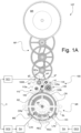
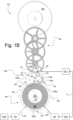
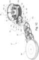
- FIGS. 1A-C to 6A-B illustrate a first variant embodiment of a watch mechanism according to the first aspect of the invention, designated overall by the reference sign 10T, comprising a rotating regulating system SR capable of operating as a tourbillon, including a rotating cage CR, or tourbillon cage, carrying an escapement EC and a regulating organ, such as a sprung balance BL.
- the escapement EC is of a conventional type comprising an escape wheel including an escape pinion PEC and an escape wheel REC conventionally cooperating with an anchor (not shown) which is actuated by the oscillating movement of the shaft of the sprung balance BL.
- the illustrations are essentially schematic and functional in that they illustrate the function of the various components without necessarily being representative of their arrangement in practice which may vary depending on the actual positioning of the various components in a watch movement.
- the rotating regulating system SR is kinematically linked to a finishing train RF conventionally driven by at least one barrel BR, which are represented schematically in the Figures 1A to 1C .
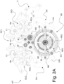
- the rotating regulating system SR is capable of operating according to a first operating mode (or “tourbillon mode”), illustrated by the Figures 1A-C And 2A-B , where the rotating cage CR is driven in rotation and according to a second operating mode (or “classic escapement mode”), illustrated by the Figures 3A-B And 4 , where the rotating cage CR is immobilized while ensuring continuity of operation of the escapement EC and the regulating organ BL.
- the finishing train RF is kinematically linked to the rotating regulating system SR via a switchable drive device 100 between a first configuration and at least one second configuration.
- the rotating regulating system SR is operated according to the first operating mode (namely in the manner of a conventional tourbillon) and the going train RF is kinematically linked to the rotating cage CR (and therefore also to the escapement EC) via the drive device 100, thus driving the rotating cage CR in rotation about its rotation axis AR.
- the rotating regulating system SR is operated according to the second operating mode (in the manner of a conventional escapement) and the going train RF is disengaged from the rotating cage CR, allowing the latter to be immobilized, the going train RF remaining kinematically linked to the escapement EC.
- the rotating cage CR is driven in rotation, in the first operating mode, so that the escape pinion PEC is driven in rotation, with the rotating cage CR, around a wheel RE of a drive wheel ME, arranged coaxially with the rotating cage CR, which is immobilized, in the first operating mode.
- this drive wheel ME is released in rotation and kinematically linked to the finishing gear RF via the drive device 100 which occupies the second configuration, while the rotating cage CR is immobilized, the drive wheel ME then being driven in rotation around its axis of rotation AR.
- the drive device 100 preferably comprises a lever 100B pivotally mounted around a pivot axis AP coinciding with the axis of a drive wheel set 105 (or input wheel set) of the drive device 100.
- This drive wheel set 105 is in permanent engagement with a wheel set RFe of the finishing gear RF, it being understood that the drive device 100 is thus in permanent kinematic connection with the finishing gear RF via the drive wheel set 105.
- This lever 100B carries a first wheel set 110 driven in rotation by the drive wheel set 105 and capable of selectively ensuring the rotational drive of the rotary cage CR, in the first configuration of the training device 100, illustrated in the Figures 1A-C And 2A-B , and to interrupt the rotational drive of the rotating cage CR, in the second configuration of the drive device 100, illustrated in the Figures 3A-B And 4
- the rocker 100B also carries a second mobile 120 driven in rotation by the drive mobile 105 (here via a mobile forming a return 115 also carried by the rocker 100B) and capable of selectively ensuring the rotational driving of the drive mobile ME, in the second configuration of the drive device 100, illustrated in the Figures 3A-B And 4 , and to interrupt the rotational drive of the drive mobile ME, in the first configuration of the drive device 100, illustrated in the Figures 1A-C And 2A-B .
- the first mobile 110 comprises a first drive wheel 110a (here an upper wheel) arranged to selectively engage, in the first configuration of the drive device 100, with a toothing CRa of the rotary cage CR, as illustrated schematically in the Figures 1A , 1C And 2B , and to be disengaged from the teeth CRa of the rotating cage CR, in the second configuration of the drive device 100, as schematically illustrated in the Figures 3A-B .
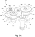
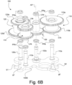
- the first mobile 110 is permanently rotated by the driving mobile 105 via the cooperation of a lower wheel 110b of the first mobile 110 and a corresponding wheel of the driving mobile 105, as illustrated in the Figures 1C , 6A And 6B .
- the second mobile 120 comprises a second drive wheel 120b (here a lower wheel) arranged to selectively engage, in the second configuration of the drive device 100, with a toothing MEa of the drive mobile ME, as illustrated schematically in the Figures 3B And 4 , and to be disengaged from the teeth MEa of the drive mobile ME, in the first configuration of the drive device 100, as schematically illustrated in the Figure 1B .
- the second mobile 120 is also permanently driven in rotation by the drive mobile 105 via the cooperation of an upper wheel 120a of the second mobile 120 in engaged with the mobile forming a return 115, itself engaged with the driving mobile 105, as illustrated in the Figures 1A , 1C , 3A , 6A And 6B .
- the configuration of the drive device 100 could be different, as well as the configuration of the first and second mobiles 110 and 120, while ensuring the selective drive functions of the rotary cage CR, on the one hand, and of the drive mobile ME, on the other hand.
- the mobile forming a return 115 could perfectly well be offset between the second mobile 120 (then arranged in permanent engagement with the drive mobile 105) and the drive mobile ME so as to be in permanent engagement with the toothing MEa of this drive mobile ME, in which case the disengagement would take place between the toothing of the second mobile 120 and the toothing of the mobile forming a return.
- FIGS. 6A And 6B show a particularly advantageous embodiment of the switchable drive device 100 where the mobiles 105, 110, 115 and 120 are each provided with a hollow shaft and a double jewel setting PRa/PRb comprising first and second stones PRa, PRb, such as rubies, in order to rotatably mount each mobile 105, 110, 115, 120 on a corresponding axis 105x, 110x, 115x, resp. 120x carried by the lever 100B.
- Each double jewel setting PRa-PRb is preferably produced by setting the first and second stones PRa, PRb on the two ends of the hollow shaft of each mobile 105, 110, 115 and 120.
- each of the ends of the hollow shaft can advantageously be provided with a dimensioned seat (see also the sectional view of the Figure 5 which passes through the axis of the drive mobile 105) to accommodate the associated stone PRa, resp. PRb and a peripheral lip LVa, LVb designed to ensure the setting of the associated stone PRa, resp. PRb.
- this lip LVa, LVb is suitably deformed on the associated stone PRa, PRb by means, for example, of a burnisher so as to set it.
- each lip LVa, LVb advantageously has a thin thickness (for example of the order of 0.01 mm at its end) facilitating its deformation and its folding towards and around each stone PRa, PRb.
- each mobile 105, 110, 115, 120 can be made of any material capable of allowing this setting, in particular a metal such as steel. This is a reasonably simple technique to implement and guarantees optimal guidance of each mobile 105, 110, 115, resp. 120 on each corresponding axis 105x, 110x, 115x, resp. 120x, and allows friction to be drastically reduced.
- FIG. 5 is a schematic perspective view of a cross-section of the rotating regulating system SR of the 10T watch mechanism.
- the cross-section is made along a vertical cutting plane passing through the rotation axis AR of the rotating cage CR (and the drive wheel set ME) and the pivot axis AP of the lever 100B of the switchable drive device 100.
- Figure 5 shows for illustration purposes the rotating regulating system SR in an angular position such that the axis of rotation of the escapement wheel of the EC escapement coincides with the section plane concerned for the purposes of the illustration.
- Figure 5 thus shows the escape wheel REC and the escape pinion PEC which meshes with the teeth of the wheel RE of the drive wheel ME.
- the rotation axis AR of the rotating cage CR coincides with the rotation axis of the balance spring BL.
- the rotating cage CR is mounted on a central pivot carried by a plate PL of the movement and guided radially by a first bearing RL1 whose outer ring is retained in a groove formed in the inner periphery of a central cylindrical support assembly carried by the plate PL.
- the external toothing CRa with which selectively engages, in the first operating mode, the drive wheel 110a of the first mobile 110 of the drive device 100.
- a first star ETa made integral with the rotating cage CR is also visible in the Figure 5 , here in the immediate vicinity of the CRa toothing. As discussed below, this first ETa star is intended to allow the selective angular immobilization of the rotating cage CR, in the second operating mode.
- the drive mobile ME is guided in rotation by means of a second bearing RL2 whose outer ring is retained in a groove arranged in the inner periphery of an external cylindrical support assembly also carried by the plate PL.
- the drive wheel ME is here made up of an upper part (including the wheel RE which meshes with the escape pinion PEC) and a lower part (including the lower external toothing MEa which meshes with the drive wheel 120b of the second wheel 120 mentioned above, not visible in the Figure 5 ).
- These upper and lower parts are made integral with each other, for example by screwing, so as to grip the inner ring of the second bearing RL2, thus ensuring the radial and axial guidance of the drive mobile ME.
- the drive mobile ME is thus positioned, in the example illustrated, around the central pivot of the rotating cage CR.
- a second star ETb made integral with the drive mobile ME is also visible in the Figure 5 , here in the immediate vicinity of the lower external toothing MEa of the drive mobile ME. As discussed below, this second star ETb, is intended to allow the selective angular immobilization of the drive mobile ME, in the first operating mode.
- the upper end of the axis 105x carrying the drive mobile 105 projects beyond the drive mobile 105 (as illustrated in the Figure 6A ) in order to form a pivot to ensure the guidance of the pivoting movement of the rocker 100B around the pivot axis AP.
- this upper end of the axis 105x is here received in a stone bearing carried by a bridge, partially visible in the Figure 5 , which is made integral with the PL plate.
- this stopping device DA comprises a first stopping lever LAa capable of selectively cooperating with the first star ETa secured to the rotating cage CR (as illustrated more specifically in the Figures 2A And 4 ) and a second stop lever LAb capable of cooperating selectively with the second star ETb secured to the drive mobile ME (as illustrated more specifically in the Figures 2A-B ).
- the switching of the drive device 100 between the first and second configurations and the actuation of the stopping device DA are advantageously controlled by a command C (see Figures 1A-B to 4 ) manually operable in order to operate the rotating regulating system SR according to the first or second operating mode.
- a command C manually operable in order to operate the rotating regulating system SR according to the first or second operating mode.
- it is a control C with two column wheels RCa, RCb which control the pivoting of the rocker 100B, on the one hand, and the actuation of the stop levers LAa and LAb, on the other hand, which are actuated alternately according to the position of the column wheels RCa, RCb.
- two control devices DC1 and DC2 can be functionally identified, sharing the same column wheels RCa, RCb, which respectively control the position of the rocker 100B and the actuation of the stop device DA.
- the control C more particularly comprises a ratchet control lever LC actuated by a push button (not shown) which cooperates with the ratchet of the first column wheel RCa which is conventionally indexed in position by a jumper.
- This first column wheel RCa is also integral with a first control wheel Ra which meshes with a first intermediate wheel R1.
- This first intermediate wheel R1 meshes with a second intermediate wheel R2 which itself meshes with a second control wheel Rb integral with the second column wheel RCb, also indexed in position by a jumper.
- the angular position of the second column wheel RCb is thus linked to the angular position of the first column wheel RCa via the gear train Ra, R1, R2, Rb. More precisely, the column wheels RCa, RCb are arranged and linked so that they control the associated stop levers LAa, LAb alternately.
- the first column wheel RCa is arranged so that a beak of the first stop lever LAa rests on one of the columns of the first column wheel RCa, thereby causing a withdrawal of the opposite end of the first stop lever LAa from the teeth of the first star ETa, thereby allowing rotation of the rotary cage CR.
- the second column wheel RCb occupies an angular position such that a beak of the second stop lever LAb falls into the space provided between two successive columns of the second column wheel RCb, thus causing an engagement of the opposite end of the second stop lever LAb in mesh with the teeth of the second star ETb.
- the drive wheel ME is therefore immobilized.
- the control C further comprises a pair of intermediate control levers L1, L2 actuated, for one, by the first column wheel RCa and, for the other, by the second column wheel RCb.
- This pair of intermediate control levers L1, L2 actuates and controls the angular position of the lever 100B of the switchable drive device 100 via a pair of actuating pins g1, g2 carried by the lever 100B.
- the lever 100B also carries first and second stops b1, b2 intended to cooperate with a pair of stop pins carried by the plate PL of the movement, which are shown in the Figures 2A-B And 4 .
- stop pins are thus arranged so as to limit the pivoting of the rocker 100B and define two determined angular positions of the rocker 100B, as illustrated in the Figures 2A-B , on the one hand, and in the Figure 4 , on the other hand.
- the terminal ends of the intermediate control levers L1, L2 cooperate selectively with the actuating pins g1, g2 so as to place the rocker 100B in one or the other of these two determined angular positions.
- the angular position occupied by the rocker 100B is such that the stop b1 is brought into contact with the associated stop pin, thus causing the clutch of the drive device 100, or more precisely of the drive wheel 120b of the second mobile 120, with the toothing MEa of the mobile ME drive, thus leading to the rotational drive of the ME drive mobile.
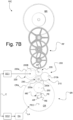
- FIGS. 7A-C And 8A-B schematically and functionally illustrate a second alternative embodiment of a watch mechanism according to the first aspect of the invention, designated overall by the reference sign 10C, comprising a rotating regulating system SR capable of operating as a carousel, including a rotating cage CR, or carousel cage, likewise carrying an escapement EC (including an escape wheel comprising an escape pinion PEC and an escape wheel REC conventionally cooperating with an anchor not shown) and a regulating member, such as a sprung balance BL.
- an escapement EC including an escape wheel comprising an escape pinion PEC and an escape wheel REC conventionally cooperating with an anchor not shown
- a regulating member such as a sprung balance BL.
- the balance spring of the sprung balance BL as well as the anchor of the escapement EC have been omitted from the illustrations for the sake of simplification.
- the illustrations are essentially schematic and functional in that they illustrate the function of the various components without necessarily being representative of their arrangement in practice
- the rotating regulating system SR is kinematically linked to a finishing train RF conventionally driven by at least one barrel BR, which are represented schematically in the Figures 7A-C And 8A-B .
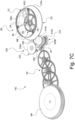
- the rotating regulating system SR is capable of operating according to a first operating mode (or “carousel mode”), illustrated by the Figures 7A-C , where the rotating cage CR is driven in rotation and according to a second operating mode (or “classic escapement mode”), illustrated by the Figures 8A-B , where the rotating cage CR is immobilized while ensuring continuity of operation of the escapement EC and the regulating organ BL.
- the going train RF is kinematically linked to the rotating regulating system SR via a drive device 200 switchable between a first configuration and at least one second configuration.
- the rotating regulating system SR is operated according to the first operating mode (namely in the manner of a conventional carousel) and the going train RF is kinematically linked to the rotating cage CR as well as to the escapement EC via the drive device 200, thus driving the rotating cage CR in rotation around its rotation axis AR.
- the rotating regulating system SR is operated according to the second operating mode (in the manner of a conventional escapement) and the going train RF is disengaged from the rotating cage CR, allowing the latter to be immobilized, the going train RF remaining kinematically linked to the escapement EC.
- the rotating cage CR is driven in rotation, in the first operating mode, so that the escape pinion PEC is driven in rotation, with the rotating cage CR, around a wheel RE of a drive wheel set ME, arranged coaxially with the rotating cage CR, itself kinematically linked to the finishing gear RF so as to be driven in rotation via the drive device 200 at a first rotational speed, in this first operating mode.
- the drive wheel set ME is driven in rotation via the drive device 200 at a second rotational speed, different from the first rotational speed.
- the drive device 200 preferably comprises a lever 200B which is pivotally mounted around a pivot axis AP coinciding here with the axis of a drive wheel set 205 (or input wheel set) of the drive device 200 which is in permanent kinematic connection with the finishing gear RF.
- This lever 200B carries a first wheel set 210 driven in rotation by the drive wheel set 205 and capable of selectively ensuring the rotational drive of the rotary cage CR, in the first configuration of the drive device 200, illustrated in the Figures 7A-C , and to interrupt the rotational drive of the rotating cage CR, in the second configuration of the drive device 200, illustrated in the Figures 8A-B .
- the first mobile 210 also ensures the rotational drive of the drive mobile ME at the first rotation speed.
- the rocker 200B also carries a second mobile 220 driven in rotation by the drive mobile 205 and capable of selectively ensuring the rotational drive of the drive mobile ME at the second rotation speed, in the second configuration of the drive device 200, illustrated in the Figures 8A-B .
- the first mobile 210 comprises a first drive wheel 210a (here an upper wheel) arranged to selectively engage, in the first configuration of the drive device 200, with a toothing CRa of the rotary cage CR, as illustrated schematically in the Figures 7A And 7C , and to be disengaged from the teeth CRa of the rotating cage CR, in the second configuration of the drive device 200, as schematically illustrated in the Figure 8A .
- the first mobile 210 is permanently rotated by the driving mobile 205 via the cooperation of a lower wheel 210b of the first mobile 210 and a corresponding lower wheel of the driving mobile 205, as illustrated in the Figures 7B , 7C And 8B .
- This lower wheel 210b also plays the role of a second drive wheel which is arranged to selectively engage, in the first configuration of the drive device 200, with an intermediate mobile 230 ensuring the driving of the drive mobile ME, as illustrated in the Figure 7B . More specifically, the lower wheel 210b of the first mobile 210 is arranged to engage with a corresponding lower wheel 230b of the intermediate mobile 230. In the second configuration of the drive device 200, the second drive wheel 210b is disengaged from the intermediate mobile 230, as illustrated in the Figure 8B .
- the second mobile 220 comprises a third drive wheel 220a (here an upper wheel) arranged to selectively engage, in the second configuration of the drive device 200, with the intermediate mobile 230, as illustrated in the Figures 8A-B , and to be disengaged from the intermediate mobile 230, in the first configuration of the drive device 200, as illustrated in the Figures 7A-C .
- the third drive wheel 220a is arranged to engage with an upper wheel corresponding 230a of the intermediate mobile 230.
- the second mobile 220 is also permanently driven in rotation by the driving mobile 205 via the cooperation of the driving wheel 220a of the second mobile 220 and a corresponding upper wheel of the driving mobile 205, as illustrated in the Figures 7A , 7C And 8A .
- the intermediate mobile 230 is kinematically linked to the drive mobile ME via an intermediate wheel 250 itself engaged with a pinion PE of the drive mobile ME, as illustrated in the Figures 7B And 8B .
- the reduction/multiplication ratio determined by the mutual cooperation of the mobiles 205, 210, 220 and 230 will be modified accordingly, thus making it possible to impact the effective rotation speed of the drive mobile ME depending on the selected operating mode.
- the configuration of the drive device 200 could be different, as well as the configuration of the mobiles 205, 210, 220, 230 and 250, while ensuring the functions of selective driving of the rotary cage CR, on the one hand, and the driving of the drive mobile ME at the two different rotation speeds, on the other hand.
- this stopping device DA may comprise a stopping lever LA, similar to the stopping lever LAa of the first embodiment variant, capable of cooperating selectively with a star (not shown) integral with the rotating cage CR (like what was previously discussed in relation to the tourbillon variant of the Figures 1A-C to 6A-B ).
- the switching of the drive device 200 between the first and second configurations and the actuation of the stop device DA can also advantageously be controlled by a control C, analogous to the control illustrated in the Figures 2A And 4 (the second stop lever LAb can be omitted in this case), manually operable in order to operate the rotating regulating system SR according to the first or second operating mode.
- This can again be a double column wheel control RCa, RCb which control the pivoting of the rocker 200B, on the one hand, and the actuation of the stop lever LA, on the other hand.
- a control would always functionally comprise two control devices DC1 and DC2, as illustrated functionally in the Figures 7A-B And 8A-B , which respectively control the position of the rocker 200B and the actuation of the stop device DA.
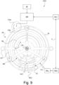
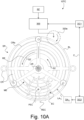
- FIGS. 9 to 10A-B schematically and functionally illustrate an alternative embodiment of a timepiece mechanism according to the second aspect of the invention, designated overall by the reference sign 10TC, comprising a rotating regulating system SR including a rotating cage CR likewise carrying an escapement EC (including an escapement wheel and pinion PEC and an escape wheel REC conventionally cooperating with an anchor not shown) and a regulating member, such as a sprung balance BL.
- an escapement EC including an escapement wheel and pinion PEC and an escape wheel REC conventionally cooperating with an anchor not shown
- a regulating member such as a sprung balance BL.
- the rotating regulating system SR further comprises a drive wheel and pinion ME, arranged coaxially with the rotating cage CR, which is structurally similar to the drive mobile described with reference to the embodiment variant of the Figures 1A-C to 6A-B .
- the illustrations are essentially schematic and functional in that they illustrate the function of the various components without necessarily being representative of their arrangement in practice which may vary depending on the actual positioning of the various components in a watch movement.
- the SR rotating regulating system of the Figures 9 And 10A-B is kinematically linked to a RF finishing train conventionally driven by at least one barrel (not shown) like the embodiment variants described previously.
- the rotating regulating system SR is capable of operating according to a first operating mode (or “tourbillon mode”), illustrated by the Figure 9 , where the rotating cage CR is driven in rotation around its rotation axis AR in a first direction of rotation S1 (here in a clockwise direction, seen from above) and in a second operating mode (or “carousel mode”), illustrated by the Figure 10A-B , where the rotating cage CR is rotated about its rotation axis AR in a second direction of rotation S2 opposite to the first direction of rotation S1.
- the drive mobile ME In the first operating mode, the drive mobile ME is immobilized, whereas in the second operating mode, the drive mobile ME is rotated in a direction of rotation S2' which is identical to the second direction of rotation S2, but at a rotation speed greater than that of the rotating cage CR.
- the 10TC watch mechanism has the particularity and originality of combining the functions of a tourbillon and a carousel in a single watch mechanism, while offering the singularity of allowing a selective inversion of the direction of rotation of the rotating cage CR of the rotating regulating system SR when switching from one operating mode to another.
- the RF finishing gear is kinematically linked to the rotating regulating system SR via a drive device 300 (shown schematically) which is switchable between a first configuration and at least a second configuration.
- the rotating regulating system SR is operated according to the first operating mode (namely in the manner of a tourbillon) and the finishing gear RF is kinematically linked to the rotating cage CR (and therefore also to the escapement EC) via the drive device 300, driving the rotating cage CR in rotation around its rotation axis AR in the first direction of rotation S1.
- the rotating regulating system SR is operated according to the second operating mode (in the manner of a carousel) and the finishing gear RF is kinematically linked to the rotating cage CR as well as to the drive wheel set ME via the drive device 300, this time driving the rotating cage CR and the drive wheel set ME in rotation around their axis of rotation AR in the direction of rotation S2, resp. S2', opposite to the first direction of rotation S1.
- the rotating cage CR is driven in rotation, in the first operating mode, so that the escape pinion PEC is driven in rotation in the first direction of rotation S1, with the rotating cage CR, around the wheel RE of the drive wheel set ME which is immobilized in this case.
- the drive wheel set ME is released in rotation and kinematically linked to the finishing gear RF via the drive device 300 which occupies the second configuration, so as to be driven in rotation (as is the rotating cage CR) in a direction of rotation S2' opposite to the first direction of rotation S1 and identical to the direction of rotation S2 of the rotating cage CR.
- the drive device 300 is configured so that the EC escapement can set the pace of the movement at the desired frequency regardless of the selected operating mode.
- the drive device 300 can take any appropriate architecture and comprise, for example, at least one manually actuable rocker, carrying several mobiles kinematically linked to the finishing gear RF and arranged so as to selectively engage with the teeth CRa of the rotary cage CR and the teeth MEa of the drive mobile ME, like the variant embodiments described previously.
- the rotating cage CR in the first operating mode (“whirlwind mode”), can be driven in the first direction of rotation S1 by means of a drive wheel of the drive device 300 comprising a first drive wheel 310a capable of being selectively brought into engagement with the teeth CRa of the rotating cage CR, by switching the drive device 300 into the first configuration, as schematically illustrated in the Figure 9 .
- this first drive wheel 310a is disengaged from the teeth CRa of the rotating cage CR, by switching the drive device 300 into the second configuration.
- the rotating cage CR can be driven in the second direction of rotation S2 by means of a drive wheel of the drive device 300 comprising a second drive wheel 320a capable of being selectively brought into engagement with the teeth CRa of the rotating cage CR, by switching the drive device 300 into the second configuration, as schematically illustrated in the Figure 10A .
- the drive wheel ME can be driven in the direction of rotation S2', identical to the second direction of rotation S2, by means of a drive wheel of the drive device 300 comprising a third drive wheel 330a capable of being selectively brought into engagement with the toothing MEa of the drive wheel ME, as schematically illustrated in the Figure 10B .
- the second and third drive wheels 320a, 330a are disengaged from the teeth CRa, resp. MEa, of the rotary cage CR, resp. of the drive mobile ME, by switching the drive device 300 into the first configuration.
- the operation of the drive device 300 is essentially analogous to that of the drive device 100 or 200 previously described, except that the rotating cage CR is no longer immobilized in the second mode of operation.
- this stopping device DA TC may comprise a stopping lever LA TC , similar to the stopping lever LAb of the first embodiment variant, capable of cooperating selectively with a star (not shown) secured to the drive wheel ME (like what was previously discussed in relation to the tourbillon variant of the Figures 1A-C to 6A-B ).
- the switching of the drive device 300 between the first and second configurations and the actuation of the stopping device DA TC can also advantageously be controlled by a control C, analogous to the control illustrated in the Figures 2A And 2B (the first stop lever LAa which can be omitted in this case), manually operable in order to operate the rotating regulating system SR according to the first or second operating mode.
- This can again be a double column wheel control RCa, RCb which control the switching of the drive device 300 between its two configurations, on the one hand, and the actuation of the stop lever LA TC , on the other hand.
- a control would always functionally comprise two control devices DC1 and DC2, as illustrated functionally in the Figures 9 And 10A-B , which respectively control the switching of the drive device 300 and the actuation of the stopping device DA TC .
- the drive device 100, 200 respectively 300 is permanently driven by the going train RF and kinematically connected to the rotating regulating system SR without interruption of the kinematic connection during the switching of the drive device 100, 200 respectively 300 between the first and second configurations, in order to avoid any interruption of the kinematic chain between the barrel BR and the escapement EC.
- This can be ensured by an appropriate geometry of the mobiles concerned and their toothing so that, when switching the drive device 100, 200, respectively 300, the kinematic connection between the going train RF is always at least partially established with the rotating cage CR and/or the drive mobile ME.
- any suitable tooth geometry will also be adopted with regard to the CRa, MEa teeth, as well as the teeth of the various mobiles designed to selectively engage with these CRa, MEa teeth so as to ensure optimal engagement of the teeth concerned when switching the rotating regulating system SR from one operating mode to another.
- first and second controls actuable by means of first and second pushers, could be provided in order to selectively control the immobilization or the rotational drive of the rotary cage CR, on the one hand, and, respectively, the direction of rotation of the rotary cage CR, on the other hand, as well as, jointly, the immobilization or the rotational drive of the drive mobile ME.
- a drive device kinematically linked to the finishing gear RF and to the rotating regulating system SR and capable of adopting three distinct configurations.
- Such a switchable drive device could be based in particular on the use of two secondary rockers mounted on a main rocker and carrying the required mobiles in order to ensure the selective driving of the rotating cage CR and the drive mobile ME, depending on the selected operating mode.
- a suitable, but not limiting, mode of implementation could for example consist of (i) driving the rotating cage CR in rotation, in the first operating mode, in a clockwise direction at the rate of one complete revolution per minute, (ii) driving the drive wheel ME in rotation, in the second operating mode, in an anticlockwise direction at the rate of one complete revolution per minute, (iii) driving the drive wheel ME in rotation, in the second operating mode, in an anticlockwise direction at the rate of one complete revolution per minute, (iv) driving the drive wheel ME in rotation, in the second operating mode, in an anticlockwise direction at the rate of one complete revolution per minute, (v) driving the drive wheel ME in rotation, in the second operating mode, in an anticlockwise direction at the rate of one complete revolution per minute, (vi) driving the drive wheel ME in rotation, in the second operating mode, in an anticlockwise direction at the rate of one complete revolution per minute, (vii) driving the drive wheel ME in rotation, in the second operating mode, in an anticlockwise direction at the rate of one complete revolution per minute, (
- a drive device comprising a lever carrying the required drive mobiles
- other solutions could perfectly well be envisaged ensuring the same functions of selective engagement and disengagement of the rotating cage CR and the drive mobile ME.
- a drive mobile kinematically linked to the finishing gear train could be envisaged which is capable of being moved into a first position in order to ensure the driving of the rotating cage CR, via a first intermediate gear train, or into a second position in order to ensure the driving of the drive mobile ME, via a second intermediate gear train.
- at least part of the first intermediate gear train would be immobilized, in the second operating mode, when the rotating cage CR is immobilized.
- the invention is not limited to the specific use of a stopping device comprising one or more stopping levers each cooperating with an associated star secured to the rotary cage CR or the drive mobile ME.
- the rotary cage CR and the drive mobile ME could be selectively immobilized by other means.
Landscapes
- Physics & Mathematics (AREA)
- General Physics & Mathematics (AREA)
- Transmission Devices (AREA)
Priority Applications (1)
| Application Number | Priority Date | Filing Date | Title |
|---|---|---|---|
| EP23209909.3A EP4557014A1 (de) | 2023-11-14 | 2023-11-14 | Uhrmechanismus mit einem dreheinstellsystem und uhr mit solch einem mechanismus |
Applications Claiming Priority (1)
| Application Number | Priority Date | Filing Date | Title |
|---|---|---|---|
| EP23209909.3A EP4557014A1 (de) | 2023-11-14 | 2023-11-14 | Uhrmechanismus mit einem dreheinstellsystem und uhr mit solch einem mechanismus |
Publications (1)
| Publication Number | Publication Date |
|---|---|
| EP4557014A1 true EP4557014A1 (de) | 2025-05-21 |
Family
ID=88834109
Family Applications (1)
| Application Number | Title | Priority Date | Filing Date |
|---|---|---|---|
| EP23209909.3A Pending EP4557014A1 (de) | 2023-11-14 | 2023-11-14 | Uhrmechanismus mit einem dreheinstellsystem und uhr mit solch einem mechanismus |
Country Status (1)
| Country | Link |
|---|---|
| EP (1) | EP4557014A1 (de) |
Citations (6)
| Publication number | Priority date | Publication date | Assignee | Title |
|---|---|---|---|---|
| CH7965A (de) | 1894-01-27 | 1894-08-15 | Bahne Bonniksen | Verbesserung an Unruhuhren |
| US549287A (en) | 1892-11-24 | 1895-11-05 | Bahne bonntksen | |
| CH699784A2 (fr) * | 2008-10-23 | 2010-04-30 | Montres Breguet Sa | Mouvement d'horlogerie comprenant un carrousel. |
| EP3193216A1 (de) * | 2016-01-13 | 2017-07-19 | Richemont International S.A. | Uhrwerksmechanismus mit tourbillon |
| EP1995650B1 (de) | 2007-05-23 | 2018-03-07 | Blancpain S. A. | Uhrwerk mit einem Karussel |
| CH716422A2 (fr) * | 2019-07-23 | 2021-01-29 | Omega Sa | Dispositif limiteur d'horlogerie pour une montre comportant au moins un tourbillon ou un carrousel. |
-
2023
- 2023-11-14 EP EP23209909.3A patent/EP4557014A1/de active Pending
Patent Citations (7)
| Publication number | Priority date | Publication date | Assignee | Title |
|---|---|---|---|---|
| US549287A (en) | 1892-11-24 | 1895-11-05 | Bahne bonntksen | |
| CH7965A (de) | 1894-01-27 | 1894-08-15 | Bahne Bonniksen | Verbesserung an Unruhuhren |
| EP1995650B1 (de) | 2007-05-23 | 2018-03-07 | Blancpain S. A. | Uhrwerk mit einem Karussel |
| CH699784A2 (fr) * | 2008-10-23 | 2010-04-30 | Montres Breguet Sa | Mouvement d'horlogerie comprenant un carrousel. |
| EP3193216A1 (de) * | 2016-01-13 | 2017-07-19 | Richemont International S.A. | Uhrwerksmechanismus mit tourbillon |
| EP3193216B1 (de) | 2016-01-13 | 2019-09-25 | Richemont International S.A. | Uhrwerksmechanismus mit tourbillon |
| CH716422A2 (fr) * | 2019-07-23 | 2021-01-29 | Omega Sa | Dispositif limiteur d'horlogerie pour une montre comportant au moins un tourbillon ou un carrousel. |
Non-Patent Citations (1)
| Title |
|---|
| P. AUGEREAU: "Etude comparative entre le tourbillon Breguet et la carrousel du Danois Bonniksen", 6ÈME CONGRÈS EUROPÉEN DE CHRONOMÉTRIE (CEC, vol. 37, 17 October 1996 (1996-10-17), pages 179 - 182, XP000641599 |
Similar Documents
| Publication | Publication Date | Title |
|---|---|---|
| EP2407833B1 (de) | Spielausgleichsmechanismus für Uhrwerk | |
| EP0608535B1 (de) | Uhrwerk mit zwei entgegengesetzten Analoganzeigen | |
| CH705116B1 (fr) | Mécanisme de calendrier ayant des moyens d'entraînement et de correction pour deux indicateurs. | |
| EP3382468B1 (de) | Uhrwerk mit verlängerung der gangreserve | |
| EP0218926B1 (de) | Vorrichtung zur schrittweisen Vorwärtsbewegung eines zeitanzeigenden Organs in einem Uhrwerk | |
| EP3904964B1 (de) | Anzeigevorrichtung einer uhrzeitanzeige oder eines abgeleiteten uhrzeitwerts und indexierungsvorrichtung | |
| EP2663902B1 (de) | Uhr | |
| CH693833A5 (fr) | Mécanisme d'horlogerie incluant un tourbillon. | |
| EP2096504B1 (de) | Mechanismus zur Anzeige der toten Sekunden | |
| CH721292A2 (fr) | Mécanisme horloger comprenant un système réglant tournant | |
| EP4254079B1 (de) | Mechanismus zur anzeige der mondphasen für uhr | |
| EP1178373A1 (de) | Uhr | |
| EP0479147B1 (de) | Mechanische und/oder elektromechanische Uhr | |
| EP3904962B1 (de) | Indexierungsvorrichtung und anzeigevorrichtung einer uhrzeitanzeige oder eines abgeleiteten uhrzeitwerts | |
| EP2455823B1 (de) | Uhr mit Weltzeitanzeige | |
| EP3629101B1 (de) | Uhranzeigemechanismus | |
| CH699784A2 (fr) | Mouvement d'horlogerie comprenant un carrousel. | |
| EP0504623A1 (de) | Doppelzeitzone mit durchquerender Achse und Zeiteinstellung über die Krone | |
| EP1461667B1 (de) | Mechanisch angetriebene uhr, verbunden mit einem chronograph | |
| EP1353244B1 (de) | Uhr mit länglichem Gehäuse | |
| EP1150184B1 (de) | Uhrwerk | |
| CH718021B1 (fr) | Mécanisme d'affichage d'information, mouvement et pièce d'horlogerie | |
| CH719556B1 (fr) | Mécanisme d'affichage des phases de lune de pièce d'horlogerie | |
| CH713658B1 (fr) | Mouvement horloger comprenant deux organes réglants. | |
| CH721149B9 (fr) | Mouvement horloger comprenant au moins un mécanisme de chronographe avec un dispositif d'embrayage axial |
Legal Events
| Date | Code | Title | Description |
|---|---|---|---|
| PUAI | Public reference made under article 153(3) epc to a published international application that has entered the european phase |
Free format text: ORIGINAL CODE: 0009012 |
|
| STAA | Information on the status of an ep patent application or granted ep patent |
Free format text: STATUS: THE APPLICATION HAS BEEN PUBLISHED |
|
| AK | Designated contracting states |
Kind code of ref document: A1 Designated state(s): AL AT BE BG CH CY CZ DE DK EE ES FI FR GB GR HR HU IE IS IT LI LT LU LV MC ME MK MT NL NO PL PT RO RS SE SI SK SM TR |
|
| STAA | Information on the status of an ep patent application or granted ep patent |
Free format text: STATUS: REQUEST FOR EXAMINATION WAS MADE |
|
| 17P | Request for examination filed |
Effective date: 20251120 |