EP4557020A1 - Procédé de fabrication d'un oscillateur balancier-spiral pour spiraux à forte variation de couple - Google Patents
Procédé de fabrication d'un oscillateur balancier-spiral pour spiraux à forte variation de couple Download PDFInfo
- Publication number
- EP4557020A1 EP4557020A1 EP23210963.7A EP23210963A EP4557020A1 EP 4557020 A1 EP4557020 A1 EP 4557020A1 EP 23210963 A EP23210963 A EP 23210963A EP 4557020 A1 EP4557020 A1 EP 4557020A1
- Authority
- EP
- European Patent Office
- Prior art keywords
- spiral springs
- manufacturing
- spiral
- turns
- balance
- Prior art date
- Legal status (The legal status is an assumption and is not a legal conclusion. Google has not performed a legal analysis and makes no representation as to the accuracy of the status listed.)
- Pending
Links
Images

Classifications
-
- G—PHYSICS
- G04—HOROLOGY
- G04B—MECHANICALLY-DRIVEN CLOCKS OR WATCHES; MECHANICAL PARTS OF CLOCKS OR WATCHES IN GENERAL; TIME PIECES USING THE POSITION OF THE SUN, MOON OR STARS
- G04B17/00—Mechanisms for stabilising frequency
- G04B17/04—Oscillators acting by spring tension
- G04B17/06—Oscillators with hairsprings, e.g. balance
- G04B17/066—Manufacture of the spiral spring
-
- G—PHYSICS
- G06—COMPUTING OR CALCULATING; COUNTING
- G06F—ELECTRIC DIGITAL DATA PROCESSING
- G06F18/00—Pattern recognition
- G06F18/20—Analysing
- G06F18/24—Classification techniques
- G06F18/241—Classification techniques relating to the classification model, e.g. parametric or non-parametric approaches
-
- B—PERFORMING OPERATIONS; TRANSPORTING
- B21—MECHANICAL METAL-WORKING WITHOUT ESSENTIALLY REMOVING MATERIAL; PUNCHING METAL
- B21C—MANUFACTURE OF METAL SHEETS, WIRE, RODS, TUBES, PROFILES OR LIKE SEMI-MANUFACTURED PRODUCTS OTHERWISE THAN BY ROLLING; AUXILIARY OPERATIONS USED IN CONNECTION WITH METAL-WORKING WITHOUT ESSENTIALLY REMOVING MATERIAL
- B21C1/00—Manufacture of metal sheets, wire, rods, tubes or like semi-manufactured products by drawing
- B21C1/02—Drawing metal wire or like flexible metallic material by drawing machines or apparatus in which the drawing action is effected by drums
-
- G—PHYSICS
- G04—HOROLOGY
- G04B—MECHANICALLY-DRIVEN CLOCKS OR WATCHES; MECHANICAL PARTS OF CLOCKS OR WATCHES IN GENERAL; TIME PIECES USING THE POSITION OF THE SUN, MOON OR STARS
- G04B17/00—Mechanisms for stabilising frequency
- G04B17/04—Oscillators acting by spring tension
- G04B17/06—Oscillators with hairsprings, e.g. balance
- G04B17/063—Balance construction
-
- G—PHYSICS
- G04—HOROLOGY
- G04D—APPARATUS OR TOOLS SPECIALLY DESIGNED FOR MAKING OR MAINTAINING CLOCKS OR WATCHES
- G04D7/00—Measuring, counting, calibrating, testing or regulating apparatus
- G04D7/08—Measuring, counting, calibrating, testing or regulating apparatus for balance wheels
-
- G—PHYSICS
- G04—HOROLOGY
- G04D—APPARATUS OR TOOLS SPECIALLY DESIGNED FOR MAKING OR MAINTAINING CLOCKS OR WATCHES
- G04D7/00—Measuring, counting, calibrating, testing or regulating apparatus
- G04D7/10—Measuring, counting, calibrating, testing or regulating apparatus for hairsprings of balances
-
- G—PHYSICS
- G04—HOROLOGY
- G04D—APPARATUS OR TOOLS SPECIALLY DESIGNED FOR MAKING OR MAINTAINING CLOCKS OR WATCHES
- G04D7/00—Measuring, counting, calibrating, testing or regulating apparatus
- G04D7/12—Timing devices for clocks or watches for comparing the rate of the oscillating member with a standard
- G04D7/1257—Timing devices for clocks or watches for comparing the rate of the oscillating member with a standard wherein further adjustment devices are present
- G04D7/1264—Timing devices for clocks or watches for comparing the rate of the oscillating member with a standard wherein further adjustment devices are present for complete clockworks
-
- G—PHYSICS
- G04—HOROLOGY
- G04D—APPARATUS OR TOOLS SPECIALLY DESIGNED FOR MAKING OR MAINTAINING CLOCKS OR WATCHES
- G04D7/00—Measuring, counting, calibrating, testing or regulating apparatus
- G04D7/12—Timing devices for clocks or watches for comparing the rate of the oscillating member with a standard
- G04D7/1257—Timing devices for clocks or watches for comparing the rate of the oscillating member with a standard wherein further adjustment devices are present
- G04D7/1271—Timing devices for clocks or watches for comparing the rate of the oscillating member with a standard wherein further adjustment devices are present for the control mechanism only (from outside the clockwork)
- G04D7/1292—Timing devices for clocks or watches for comparing the rate of the oscillating member with a standard wherein further adjustment devices are present for the control mechanism only (from outside the clockwork) whereby the adjustment device works on the balance wheel
Definitions
- the invention relates to the general technical field of mechanical oscillators, used in particular in watchmaking. More particularly, the invention relates to a method for manufacturing oscillators comprising a spiral spring and a balance wheel.
- the first technique is very expensive, and the second technique has poor chronometric performance. Furthermore, they are not or poorly adapted when a very strong variation in the torques of the balance springs is present at the end of the manufacturing process, this makes the association with a balance wheel and the adjustments difficult, and is felt on the chronometric performance of the oscillator which is generally poor.
- the invention aims in particular to propose an economical method for assembling an oscillator.
- an objective of the invention is to propose a method for manufacturing an oscillator comprising a spiral spring and a balance wheel and consisting of having an economical method despite the large torque dispersion of the spirals.
- the invention relates to a method of manufacturing an oscillator 1 intended to equip a clockwork movement.
- Manufacturing is understood in the broad sense to mean steps in manufacturing parts of oscillator 1 as well as steps in assembling parts of oscillator 1.
- a batch of balances 2 is taken from a production, the batch of balances 2 being obtained via a process allowing a determined inertia of the balances to be obtained.
- the average inertia of the batch of balances 2 is measured to ensure that there is not too great a dispersion within the batch, any balances having an inertia that is too far removed being removed from the batch.
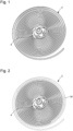
- 3-coiled spiral springs are provided, the latter having an excess number of coils forming up to three additional coils, as illustrated in Figure 1 Such an excess number of coils allows the spiral springs to be shortened later during adjustment.
- a surface layer of ductile material is deposited on the alloy blank to facilitate wire forming.
- Such a thickness of ductile material makes it easy to stretch, draw and roll the blank.
- the blank covered with the ductile surface layer is deformed via wire drawing and then rolling, then undergoes at least one heat treatment step, and finally a rolling step is carried out to form the spiral springs 3.
- a deformation step generally refers to one or more deformation treatments, which may include wire drawing and/or rolling.
- Wire drawing may require the use of one or more dies during the same deformation step or during different deformation steps if necessary.
- Wire drawing is carried out until a round-section wire is obtained.
- Rolling may be carried out during the same deformation step as wire drawing or in another subsequent deformation step.
- the last deformation treatment applied to the alloy is a rolling, preferably with a rectangular profile compatible with the entry section of a strapping spindle.
- ductile material can be galvanic, PVD or CVD, or mechanical, we then obtain a jacket or a tube of ductile material which is adjusted on the alloy blank, then which is thinned during the stage(s) of deformation of the blank.
- the ductile material is removed after all the deformation treatment operations have been carried out, i.e. after the last rolling and before the wire is drawn.
- the wire is, for example, stripped of its layer of ductile material by chemical attack, for example with an acid-based solution.
- spiral springs 3 are obtained having an excess external length of at least three turns, with an alloy core and a casing made of ductile material.
- the spiral springs 3 obtained then have a section which is variable. Indeed, the regularity of the wire forming the spiral spring is not uniform because the alloy does not deform as easily as copper and consequently the section of the wire is likely to vary following the different stages of deformation. There is therefore a high variability in torque among the spiral springs 3 produced and the “Spiromatic” system is not possible or usable in such a case.
- the method according to the invention comprises a third step during which a first external cut 30 is made to obtain a pre-cut spiral spring 3, as illustrated in Figure 2
- the length of the outer cut 30 is made over one or two turns so that there remains a surplus length on the spiral spring 3 to make a second subsequent cut when adjusting the spiral spring 3 on the balance wheel 2.
- the torque of the spiral springs 3 is measured, and the spiral springs 3 are sorted according to the measured torque value to form batches of spirals having a similar measured torque.
- the spiral springs 3 are assembled, the measured torque of which corresponds to the inertia of the balance wheels 2, to form an oscillator of an intermediate frequency and to determine the length to be cut to reach a desired oscillation frequency.
- a second outer cut of the selected spiral spring 3 is made to achieve both the desired oscillation frequency, and to achieve a target value for the angle ⁇ formed by the attachment point 6 of the spiral spring 3 to a stud and the outlet 5 of the collet 4 after the second outer cut, with a tolerance of plus or minus 50° of the theoretical value.
- the theoretical value is defined so that the product requirements can be met once the curve is formed.
- the method of the invention thus makes it possible to have a balance-spring assembly tuned to a particular frequency, with good reliability and good precision.
Landscapes
- General Physics & Mathematics (AREA)
- Physics & Mathematics (AREA)
- Engineering & Computer Science (AREA)
- Manufacturing & Machinery (AREA)
- Theoretical Computer Science (AREA)
- Data Mining & Analysis (AREA)
- Mechanical Engineering (AREA)
- Life Sciences & Earth Sciences (AREA)
- Computer Vision & Pattern Recognition (AREA)
- Evolutionary Biology (AREA)
- Evolutionary Computation (AREA)
- General Engineering & Computer Science (AREA)
- Bioinformatics & Computational Biology (AREA)
- Bioinformatics & Cheminformatics (AREA)
- Artificial Intelligence (AREA)
- Springs (AREA)
Abstract
L'invention concerne un procédé de fabrication d'un oscillateur (1) pour pièce d'horlogerie réalisé à partir d'un balancier (2) et d'un ressort spiral (3), le procédé comprenant les étapes suivantes :- mesurer le moment d'inertie moyen d'un lot de balanciers (2) ;- fournir des ressorts spiraux (3) virolés, les ressorts spiraux (3) présentant un surplus de de nombre de spires formant jusque trois tours supplémentaires par rapport au nombre de spires final ;- effectuer une première coupe extérieure prédéterminée des ressorts spiraux (3) sur une longueur d'une à deux spires puis mesurer le couple des ressorts spiraux (3) et les trier en fonction de la valeur du couple mesurée ;- assembler les ressorts spiraux (3) dont le couple mesuré correspond aux balanciers (2) pour former un oscillateur d'une fréquence intermédiaire et déterminer la longueur à couper pour atteindre une fréquence d'oscillation souhaitée ;- effectuer une seconde coupe extérieure des ressorts spiraux (3) sélectionnés pour atteindre à la fois la fréquence d'oscillation souhaitée, et atteindre une valeur cible pour obtenir un angle (α) de point d'attache (6) à +/- 50° de la valeur théorique.
Description
- L'invention se rapporte au domaine technique général des oscillateurs mécaniques, utilisés notamment dans l'horlogerie. Plus particulièrement, l'invention concerne un procédé de fabrication d'oscillateurs comportant un ressort spiral et un balancier.
- Malgré l'extrême précision des usinages et leur grande reproductibilité, des ajustements doivent presque toujours être opérés, soit lors d'une opération d'assemblage, soit, plus fréquemment, lors d'une opération de réglage ou de mise au point, en particulier pour un réglage de balourd et un ajustement d'inertie dans le cas des pièces mobiles, et un réglage de fréquence dans le cas d'un oscillateur.
- C'est en particulier au stade assemblé qu'il est nécessaire de parfaire l'appairage de certains composants qui, pris indépendamment, sont dans les tolérances d'usinage ou de réalisation, mais qui ne peuvent être assemblés purement et simplement en raison des contraintes de service propre au sous-ensemble ou à l'ensemble monté.
- C'est en particulier le cas des organes réglants des pièces d'horlogerie, et tout particulièrement des ensembles balancier-spiral. Il apparaît en effet que les réglages de balourd et d'ajustement d'inertie, tant statique que dynamique, sont déjà très délicats au stade des composants individuels, et que ces opérations de mise au point se révèlent extrêmement complexes quand les composants sont assemblés. En particulier les réglages dynamiques se révèlent délicats à mettre en oeuvre. Pour l'ajustement d'un sous-ensemble balancier-spiral, on connaît différentes techniques, dont deux sont plus couramment appliquées.
- Le système « Omégamétrique » consiste à effectuer :
- un classage des spiraux déjà coupés au bon point d'attache selon leur couple ;
- un classage des balanciers selon leur inertie ;
- un appairage d'un balancier choisi dans une classe particulière, avec un spiral choisi lui aussi dans une classe particulière, ces classes étant compatibles entre elles pour atteindre la précision de fréquence choisie.
- Ce procédé impose un important stock des composants et de nombreuses contraintes logistiques.
- En alternative on connaît le système « Spiromatic » :
- on assemble en général un spiral virolé sur un balancier ;
- on coupe ce spiral à la longueur qui permet d'obtenir un couple adapté à l'inertie du balancier. Avec une bonne maîtrise des dispersions d'inertie des balanciers et de couple des spiraux, ce point de coupe se trouve dans une tolérance maximum de +/- 50° autour de la valeur cible théorique.
- Ce procédé ne permet pas de garantir une grande précision du point d'attache du ressort spiral par rapport à la sortie de la virole, ce qui peut avoir pour conséquence une perte de performance chronométrique. Ceci est particulièrement vrai lorsque les spiraux présentent une large distribution de couple nominal.
- La première technique est très coûteuse, et la seconde technique est médiocre en performance chronométrique. Par ailleurs, elles ne sont pas ou mal adaptées lorsqu'une très forte variation des couples des spiraux est présente à l'issue du procédé de fabrication, cela rend l'association à un balancier et les réglages difficiles, et se ressent sur les performances chronométriques de l'oscillateur qui sont généralement médiocres.
- L'invention a notamment pour objectif de proposer une méthode économique pour l'assemblage d'un oscillateur.
- Plus précisément, un objectif de l'invention est de proposer un procédé de fabrication d'un oscillateur comportant un ressort spiral et un balancier et consistant à avoir un procédé économique malgré la grande dispersion de couple des spiraux.
- A cet effet, l'invention concerne un procédé de fabrication d'un oscillateur pour pièce d'horlogerie réalisé à partir d'un balancier et d'un ressort spiral, le procédé comprenant les étapes suivantes :
- mesurer le moment d'inertie moyen d'un lot de balanciers ;
- fournir des spiraux virolés, les spiraux présentant un surplus de nombre de spires formant jusque trois tours supplémentaires par rapport au nombre de spires finales ;
- effectuer une première coupe extérieure prédéterminée des spiraux avec un surplus défini d'une longueur d'une à deux spires puis mesurer le couple des spiraux et les trier en fonction de la valeur du couple mesurée ;
- assembler les ressorts spiraux dont le couple mesuré correspond aux balanciers pour former un oscillateur d'une fréquence intermédiaire ;
- effectuer une seconde coupe extérieure des ressorts spiraux sélectionnés pour atteindre à la fois la fréquence d'oscillation souhaitée, et atteindre une valeur cible pour obtenir un angle de point d'attache à +/- 50° de la valeur théorique.
- Conformément à d'autres variantes avantageuses de l'invention :
- les ressorts spiraux sont élaborés à partir d'une ébauche dans un métal ou alliage métallique ;
- l'ébauche est recouverte d'une couche superficielle d'un matériau ductile ;
- le métal ou l'alliage métallique est choisi parmi le titane, le niobium, le zirconium ou une combinaison de ces métaux ;
- les ressorts spiraux sont mise en forme via une étape de tréfilage et/ou laminage de l'ébauche alternée avec au moins une étape de traitement thermique, une étape d'estrapadage pour former le ressort spiral étant effectuée avant la dernière étape de traitement thermique ;
- la couche superficielle ductile est retirée après le laminage, et avant l'estrapadage.
- D'autres caractéristiques et avantages de l'invention apparaîtront à la lecture de la description détaillée suivante donnée à titre d'exemple nullement limitatif, en référence aux dessins annexés dans lesquels :
- la
figure 1 représente un spiral virolé avec un surplus de nombre de spires ; - la
figure 2 représente un spiral virolé ayant subi une première coupe extérieure d'une à deux spires ; - la
figure 3 représente schématiquement un oscillateur obtenu via le procédé de fabrication selon l'invention. - L'invention concerne un procédé de fabrication d'un oscillateur 1 destiné à équiper un mouvement d'horlogerie.
- Par fabrication, il convient d'entendre au sens large des étapes de fabrication de parties de l'oscillateur 1 ainsi que des étapes d'assemblage de parties de l'oscillateur 1.
- Lors de la première étape, on prélève un lot de balanciers 2 parmi une production, le lot de balanciers 2 étant obtenu via un procédé permettant d'obtenir une inertie déterminée des balanciers. L'inertie moyenne du lot de balancier 2 est mesurée pour s'assurer qu'il n'y a pas une dispersion trop grande au sein du lot, les éventuels balanciers présentant une inertie trop éloignée étant écartés du lot.
- Lors de la deuxième étape, des ressorts spiraux 3 virolés sont fournis, ces derniers présentant un surplus de nombre de spires formant jusqu'à trois spires supplémentaires, comme illustré à la
figure 1 . Un tel surplus de nombre de spires permet de pouvoir raccourcir les ressorts spiraux ultérieurement dans le cadre d'un réglage. - Pour réaliser ces ressorts spiraux, on utilise une ébauche formée dans un métal ou un alliage métallique.
- Ensuite, on dépose, sur l'ébauche en alliage, une couche superficielle d'un matériau ductile pour faciliter la mise en forme sous forme de fil. Une telle épaisseur de matériau ductile permet d'étirer, de tréfiler et de laminer aisément l'ébauche.
- Enfin, pour mettre en forme les ressorts spiraux 3, l'ébauche recouverte de la couche superficielle ductile est déformée via un tréfilage puis un laminage, puis subit au moins une étape de traitement thermique, et finalement une étape d'estrapadage est effectuée pour former les ressorts spiraux 3.
- Une étape de déformation désigne d'une manière globale un ou plusieurs traitements de déformation, qui peuvent comprendre le tréfilage et/ou le laminage. Le tréfilage peut nécessiter l'utilisation d'une ou plusieurs filières lors de la même étape de déformation ou lors de différentes étapes de déformation si nécessaire. Le tréfilage est réalisé jusqu'à l'obtention d'un fil de section ronde. Le laminage peut être effectué lors de la même étape de déformation que le tréfilage ou dans une autre étape de déformation ultérieure. Avantageusement, le dernier traitement de déformation appliqué à l'alliage est un laminage, de préférence à profil rectangulaire compatible avec la section d'entrée d'une broche d'estrapadage.
- L'apport de matériau ductile peut être galvanique, PVD ou CVD, ou bien mécanique, on obtient alors une chemise ou un tube de matériau ductile qui est ajusté sur l'ébauche d'alliage, puis qui est amincie au cours de la ou des étapes de déformation de l'ébauche.
- Le matériau ductile est éliminé une fois toutes les opérations de traitement de déformation effectuées, c'est-à-dire après le dernier laminage, et avant l'estrapadage. Le fil est, par exemple, débarrassé de sa couche de matériau ductile, par attaque chimique, avec une solution à base d'acides par exemple.
- A l'issue de ces étapes, on obtient des ressorts spiraux 3 présentant un surplus de longueur extérieure d'au moins trois spires, avec une âme en alliage et une enveloppe en matériau ductile.
- Les ressorts spiraux 3 obtenus présentent alors une section qui est variable. En effet, la régularité du fil formant le ressort spiral n'est pas uniforme car l'alliage ne se déforme pas aussi facilement que le cuivre et par conséquent la section du fil est amenée à varier suite aux différentes étapes de déformations. Il y a donc une forte variabilité de couple parmi les ressorts spiraux 3 produits et le système « Spiromatic » n'est pas envisageable ou utilisable dans un tel cas.
- Le procédé selon l'invention comprend une troisième étape au cours de laquelle une première coupe extérieure 30 est réalisée pour obtenir un ressort spiral 3 prédécoupé, comme illustré à la
figure 2 . La longueur de la coupe extérieure 30 est effectuée sur une ou deux spires de manière qu'il reste un surplus de longueur sur le ressort spiral 3 pour effectuer une seconde coupe ultérieure lors du réglage du ressort spiral 3 sur le balancier 2. - Ensuite, lors de la quatrième étape, le couple des ressorts spiraux 3 est mesuré, et les ressorts spiraux 3 sont triés en fonction de la valeur du couple mesurée pour former des lots de spiraux ayant un couple mesuré similaire.
- Lors de la cinquième étape, on assemble les ressorts spiraux 3 dont le couple mesuré correspond à l'inertie des balanciers 2 pour former un oscillateur d'une fréquence intermédiaire et déterminer la longueur à couper pour atteindre une fréquence d'oscillation souhaitée.
- Ensuite, lors de la sixième étape, on effectue une seconde coupe extérieure du ressort spiral 3 sélectionné pour atteindre à la fois la fréquence d'oscillation souhaitée, et à atteindre une valeur cible pour l'angle α formé par le point d'attache 6 du ressort spiral 3 à un piton et la sortie 5 de la virole 4 après la seconde coupe extérieure, avec une tolérance de plus ou moins 50° de la valeur théorique. La valeur théorique est définie de manière à pouvoir respecter les exigences du produit une fois la courbe formée.
- Ainsi, un tel procédé permet d'associer un lot de spiraux de manière à ce que tous les spiraux de ce lot puissent être appairés au lot de balanciers en respectant la tolérance de +/- 50°.
- Le procédé de l'invention permet ainsi de disposer d'un ensemble balancier-spiral accordé à une fréquence particulière, avec une bonne fiabilité et une bonne précision.
Claims (6)
- Procédé de fabrication d'un oscillateur (1) pour pièce d'horlogerie réalisé à partir d'un balancier (2) et d'un ressort spiral (3), caractérisé en ce qu'il comprend les étapes suivantes :- mesurer le moment d'inertie moyen d'un lot de balanciers (2) ;- fournir des ressorts spiraux (3) virolés, les ressorts spiraux (3) présentant un surplus de nombre de spires formant jusque trois tours supplémentaires par rapport au nombre de spires final ;- effectuer une première coupe extérieure prédéterminée des ressorts spiraux (3) avec un surplus défini d'une longueur d'une à deux spires puis mesurer le couple des ressorts spiraux (3) et les trier en fonction de la valeur du couple mesurée ;- assembler les ressorts spiraux (3) dont le couple mesuré correspond aux balanciers (2) pour former un oscillateur d'une fréquence intermédiaire ;- effectuer une seconde coupe extérieure des ressorts spiraux (3) sélectionnés pour atteindre à la fois la fréquence d'oscillation souhaitée, et atteindre une valeur cible pour obtenir un angle (α) de point d'attache (6) à +/- 50° de la valeur théorique.
- Procédé de fabrication selon la revendication 1, caractérisé en ce que les ressorts spiraux (3) sont élaborés à partir d'une ébauche dans un métal ou un alliage métallique.
- Procédé de fabrication selon la revendication 2, caractérisé en ce que l'ébauche est recouverte d'une couche superficielle d'un matériau ductile.
- Procédé de fabrication selon la revendication 2, caractérisé en ce que le métal ou l'alliage métallique est choisi parmi le titane, le niobium, le zirconium ou une combinaison de ces métaux.
- Procédé de fabrication selon l'une des revendications 1 à 4, dans lequel les ressorts spiraux (3) sont mis en forme via une étape de tréfilage et/ou laminage de l'ébauche alternée avec au moins une étape de traitement thermique, une étape d'estrapadage pour former le ressort spiral étant effectuée avant la dernière étape de traitement thermique.
- Procédé de fabrication selon la revendication 3, caractérisé en ce que la couche superficielle ductile est retirée après le laminage, et avant l'estrapadage.
Priority Applications (4)
| Application Number | Priority Date | Filing Date | Title |
|---|---|---|---|
| EP23210963.7A EP4557020A1 (fr) | 2023-11-20 | 2023-11-20 | Procédé de fabrication d'un oscillateur balancier-spiral pour spiraux à forte variation de couple |
| US18/888,259 US20250164930A1 (en) | 2023-11-20 | 2024-09-18 | Method for manufacturing a sprung balance oscillator for high torque variation balance springs |
| JP2024160586A JP7711288B2 (ja) | 2023-11-20 | 2024-09-18 | 高トルクばらつきヒゲゼンマイのためのバネ式バランス振動子を製造する方法 |
| CN202411653036.XA CN120020649A (zh) | 2023-11-20 | 2024-11-19 | 制造用于高扭矩变化摆轮游丝的游丝摆轮振荡器的方法 |
Applications Claiming Priority (1)
| Application Number | Priority Date | Filing Date | Title |
|---|---|---|---|
| EP23210963.7A EP4557020A1 (fr) | 2023-11-20 | 2023-11-20 | Procédé de fabrication d'un oscillateur balancier-spiral pour spiraux à forte variation de couple |
Publications (1)
| Publication Number | Publication Date |
|---|---|
| EP4557020A1 true EP4557020A1 (fr) | 2025-05-21 |
Family
ID=88874529
Family Applications (1)
| Application Number | Title | Priority Date | Filing Date |
|---|---|---|---|
| EP23210963.7A Pending EP4557020A1 (fr) | 2023-11-20 | 2023-11-20 | Procédé de fabrication d'un oscillateur balancier-spiral pour spiraux à forte variation de couple |
Country Status (4)
| Country | Link |
|---|---|
| US (1) | US20250164930A1 (fr) |
| EP (1) | EP4557020A1 (fr) |
| JP (1) | JP7711288B2 (fr) |
| CN (1) | CN120020649A (fr) |
Citations (1)
| Publication number | Priority date | Publication date | Assignee | Title |
|---|---|---|---|---|
| EP2455825A1 (fr) * | 2010-11-18 | 2012-05-23 | Nivarox-FAR S.A. | Procédé d'appairage et d'ajustement d'un sous-ensemble d'horlogerie |
Family Cites Families (3)
| Publication number | Priority date | Publication date | Assignee | Title |
|---|---|---|---|---|
| EP2565727A1 (fr) * | 2011-09-05 | 2013-03-06 | Nivarox-FAR S.A. | Procédé de constitution d'un ensemble balancier-spiral d'horlogerie et d'ajustement en fréquence d'oscillation |
| EP2703909A1 (fr) * | 2012-09-04 | 2014-03-05 | The Swatch Group Research and Development Ltd. | Résonateur balancier - spiral appairé |
| EP2908183B1 (fr) * | 2014-02-14 | 2018-04-18 | ETA SA Manufacture Horlogère Suisse | Spiral d'horlogerie |
-
2023
- 2023-11-20 EP EP23210963.7A patent/EP4557020A1/fr active Pending
-
2024
- 2024-09-18 JP JP2024160586A patent/JP7711288B2/ja active Active
- 2024-09-18 US US18/888,259 patent/US20250164930A1/en active Pending
- 2024-11-19 CN CN202411653036.XA patent/CN120020649A/zh active Pending
Patent Citations (1)
| Publication number | Priority date | Publication date | Assignee | Title |
|---|---|---|---|---|
| EP2455825A1 (fr) * | 2010-11-18 | 2012-05-23 | Nivarox-FAR S.A. | Procédé d'appairage et d'ajustement d'un sous-ensemble d'horlogerie |
Non-Patent Citations (1)
| Title |
|---|
| GROUPE DES FABRICANTS SUISSES DE SPIRAUX: "Le Spiral. Ses proprietes ses qualites sa manipulation", CLASSEUR TECHNIQUE A L'USAGE DU PRATICIEN, 1 January 1969 (1969-01-01), XP055654217 * |
Also Published As
| Publication number | Publication date |
|---|---|
| JP2025083291A (ja) | 2025-05-30 |
| CN120020649A (zh) | 2025-05-20 |
| JP7711288B2 (ja) | 2025-07-22 |
| US20250164930A1 (en) | 2025-05-22 |
Similar Documents
| Publication | Publication Date | Title |
|---|---|---|
| EP2105807B1 (fr) | Spiral à élévation de courbe monobloc et son procédé de fabrication | |
| EP2175328B1 (fr) | Mouvement horloger comportant un spiral plat | |
| EP2104006B1 (fr) | Double spiral monobloc et son procédé de fabrication | |
| EP2485095B1 (fr) | Balancier composite | |
| EP3181938B1 (fr) | Procede de fabrication d'un spiral d'une raideur predeterminee par retrait de matiere | |
| EP2257856B1 (fr) | Organe régulateur monobloc et son procédé de fabrication | |
| EP1612627B1 (fr) | Spiral autocompensateur bi-matière | |
| EP3769161B1 (fr) | Procede de fabrication de spiraux horlogers thermocompenses de raideur precise | |
| EP3181939B1 (fr) | Procede de fabrication d'un spiral d'une raideur predeterminee par ajout de matiere | |
| EP1519250B1 (fr) | Résonateur balancier-spiral thermocompensé | |
| EP3601628B1 (fr) | Alliage de titane beta metastable, ressort d'horlogerie a base d'un tel alliage et son procede de fabrication | |
| CH711962A2 (fr) | Procédé de fabrication d'un spiral d'une raideur prédéterminée par retrait localisé de matière. | |
| EP2104007A1 (fr) | Spiral monobloc en matériau à base de silicium et son procédé de fabrication | |
| FR2659887A1 (fr) | Procede pour ajuster le diametre interne d'objets annulaires renforces par des filaments. | |
| EP4557020A1 (fr) | Procédé de fabrication d'un oscillateur balancier-spiral pour spiraux à forte variation de couple | |
| CH721306A2 (fr) | Procédé de fabrication d'un oscillateur balancier-spiral pour spiraux à forte variation de couple | |
| EP3617811B1 (fr) | Procédé de réalisation d'une friction par lanternage | |
| EP4121821A1 (fr) | Procede de fabrication d'un composant horloger a base de silicium | |
| EP3822709B1 (fr) | Procédé de fabrication d'un composant horloger | |
| CH719634B1 (fr) | Procédé de fabrication d'un oscillateur par appairage et assemblage d'un couple balancier/spiral | |
| EP4535092B1 (fr) | Procédé de fabrication d'un balancier pour oscillateur horloger | |
| EP1538492B1 (fr) | Cadran émaillé avec pieds et son procédé de fabrication | |
| EP4019459B1 (fr) | Procédé de fabrication d'un ressort spiral thermocompensé | |
| EP4492157A1 (fr) | Procédé de réglage de l'isochronisme d'un organe régulateur balancier-spiral | |
| CH716696A2 (fr) | Procédé de fabrication de spiraux horlogers. |
Legal Events
| Date | Code | Title | Description |
|---|---|---|---|
| PUAI | Public reference made under article 153(3) epc to a published international application that has entered the european phase |
Free format text: ORIGINAL CODE: 0009012 |
|
| STAA | Information on the status of an ep patent application or granted ep patent |
Free format text: STATUS: THE APPLICATION HAS BEEN PUBLISHED |
|
| AK | Designated contracting states |
Kind code of ref document: A1 Designated state(s): AL AT BE BG CH CY CZ DE DK EE ES FI FR GB GR HR HU IE IS IT LI LT LU LV MC ME MK MT NL NO PL PT RO RS SE SI SK SM TR |
|
| STAA | Information on the status of an ep patent application or granted ep patent |
Free format text: STATUS: REQUEST FOR EXAMINATION WAS MADE |
|
| 17P | Request for examination filed |
Effective date: 20251120 |