EP4557067A1 - Verfahren und vorrichtung zur synchronen anzeige von messdaten und computerlesbares speichermedium - Google Patents
Verfahren und vorrichtung zur synchronen anzeige von messdaten und computerlesbares speichermedium Download PDFInfo
- Publication number
- EP4557067A1 EP4557067A1 EP24167951.3A EP24167951A EP4557067A1 EP 4557067 A1 EP4557067 A1 EP 4557067A1 EP 24167951 A EP24167951 A EP 24167951A EP 4557067 A1 EP4557067 A1 EP 4557067A1
- Authority
- EP
- European Patent Office
- Prior art keywords
- measurement data
- data display
- synchronization
- paused state
- window
- Prior art date
- Legal status (The legal status is an assumption and is not a legal conclusion. Google has not performed a legal analysis and makes no representation as to the accuracy of the status listed.)
- Pending
Links
Images








Classifications
-
- G—PHYSICS
- G06—COMPUTING OR CALCULATING; COUNTING
- G06F—ELECTRIC DIGITAL DATA PROCESSING
- G06F3/00—Input arrangements for transferring data to be processed into a form capable of being handled by the computer; Output arrangements for transferring data from processing unit to output unit, e.g. interface arrangements
- G06F3/01—Input arrangements or combined input and output arrangements for interaction between user and computer
- G06F3/048—Interaction techniques based on graphical user interfaces [GUI]
- G06F3/0481—Interaction techniques based on graphical user interfaces [GUI] based on specific properties of the displayed interaction object or a metaphor-based environment, e.g. interaction with desktop elements like windows or icons, or assisted by a cursor's changing behaviour or appearance
-
- G—PHYSICS
- G06—COMPUTING OR CALCULATING; COUNTING
- G06F—ELECTRIC DIGITAL DATA PROCESSING
- G06F11/00—Error detection; Error correction; Monitoring
- G06F11/30—Monitoring
- G06F11/32—Monitoring with visual or acoustical indication of the functioning of the machine
- G06F11/321—Display for diagnostics, e.g. diagnostic result display, self-test user interface
-
- G—PHYSICS
- G06—COMPUTING OR CALCULATING; COUNTING
- G06F—ELECTRIC DIGITAL DATA PROCESSING
- G06F11/00—Error detection; Error correction; Monitoring
- G06F11/07—Responding to the occurrence of a fault, e.g. fault tolerance
- G06F11/0703—Error or fault processing not based on redundancy, i.e. by taking additional measures to deal with the error or fault not making use of redundancy in operation, in hardware, or in data representation
- G06F11/0706—Error or fault processing not based on redundancy, i.e. by taking additional measures to deal with the error or fault not making use of redundancy in operation, in hardware, or in data representation the processing taking place on a specific hardware platform or in a specific software environment
- G06F11/0736—Error or fault processing not based on redundancy, i.e. by taking additional measures to deal with the error or fault not making use of redundancy in operation, in hardware, or in data representation the processing taking place on a specific hardware platform or in a specific software environment in functional embedded systems, i.e. in a data processing system designed as a combination of hardware and software dedicated to performing a certain function
- G06F11/0739—Error or fault processing not based on redundancy, i.e. by taking additional measures to deal with the error or fault not making use of redundancy in operation, in hardware, or in data representation the processing taking place on a specific hardware platform or in a specific software environment in functional embedded systems, i.e. in a data processing system designed as a combination of hardware and software dedicated to performing a certain function in a data processing system embedded in automotive or aircraft systems
-
- G—PHYSICS
- G06—COMPUTING OR CALCULATING; COUNTING
- G06F—ELECTRIC DIGITAL DATA PROCESSING
- G06F11/00—Error detection; Error correction; Monitoring
- G06F11/22—Detection or location of defective computer hardware by testing during standby operation or during idle time, e.g. start-up testing
- G06F11/2205—Detection or location of defective computer hardware by testing during standby operation or during idle time, e.g. start-up testing using arrangements specific to the hardware being tested
- G06F11/2236—Detection or location of defective computer hardware by testing during standby operation or during idle time, e.g. start-up testing using arrangements specific to the hardware being tested to test CPU or processors
-
- G—PHYSICS
- G06—COMPUTING OR CALCULATING; COUNTING
- G06F—ELECTRIC DIGITAL DATA PROCESSING
- G06F11/00—Error detection; Error correction; Monitoring
- G06F11/30—Monitoring
- G06F11/3065—Monitoring arrangements determined by the means or processing involved in reporting the monitored data
- G06F11/3072—Monitoring arrangements determined by the means or processing involved in reporting the monitored data where the reporting involves data filtering, e.g. pattern matching, time or event triggered, adaptive or policy-based reporting
- G06F11/3075—Monitoring arrangements determined by the means or processing involved in reporting the monitored data where the reporting involves data filtering, e.g. pattern matching, time or event triggered, adaptive or policy-based reporting the data filtering being achieved in order to maintain consistency among the monitored data, e.g. ensuring that the monitored data belong to the same timeframe, to the same system or component
-
- G—PHYSICS
- G06—COMPUTING OR CALCULATING; COUNTING
- G06F—ELECTRIC DIGITAL DATA PROCESSING
- G06F9/00—Arrangements for program control, e.g. control units
- G06F9/06—Arrangements for program control, e.g. control units using stored programs, i.e. using an internal store of processing equipment to receive or retain programs
- G06F9/44—Arrangements for executing specific programs
- G06F9/451—Execution arrangements for user interfaces
- G06F9/452—Remote windowing, e.g. X-Window System, desktop virtualisation
-
- G—PHYSICS
- G06—COMPUTING OR CALCULATING; COUNTING
- G06F—ELECTRIC DIGITAL DATA PROCESSING
- G06F2203/00—Indexing scheme relating to G06F3/00 - G06F3/048
- G06F2203/048—Indexing scheme relating to G06F3/048
- G06F2203/04803—Split screen, i.e. subdividing the display area or the window area into separate subareas
-
- H—ELECTRICITY
- H04—ELECTRIC COMMUNICATION TECHNIQUE
- H04L—TRANSMISSION OF DIGITAL INFORMATION, e.g. TELEGRAPHIC COMMUNICATION
- H04L12/00—Data switching networks
- H04L12/28—Data switching networks characterised by path configuration, e.g. LAN [Local Area Networks] or WAN [Wide Area Networks]
- H04L12/40—Bus networks
- H04L2012/40208—Bus networks characterized by the use of a particular bus standard
- H04L2012/40215—Controller Area Network CAN
-
- H—ELECTRICITY
- H04—ELECTRIC COMMUNICATION TECHNIQUE
- H04L—TRANSMISSION OF DIGITAL INFORMATION, e.g. TELEGRAPHIC COMMUNICATION
- H04L12/00—Data switching networks
- H04L12/28—Data switching networks characterised by path configuration, e.g. LAN [Local Area Networks] or WAN [Wide Area Networks]
- H04L12/40—Bus networks
- H04L2012/40267—Bus for use in transportation systems
- H04L2012/40273—Bus for use in transportation systems the transportation system being a vehicle
Definitions
- the present disclosure relates to the field of data processing technologies and in particular to a method and system for synchronously displaying measurement data.
- the measurement data display window in a vehicular software needs to display a plurality of signals, for example, the graphical window needs to display a curve of multiple signals.
- these signals are to be grouped, for example, a group relating to a power assembly, and a group relating to chassis electric control. These different groups are to be displayed on different measurement data display windows to avoid mutual influence.
- the present disclosure provides a method of synchronously displaying measurement data, including:
- the measurement data display window in a vehicular software needs to display a plurality of signals, for example, the graphical window needs to display a curve of multiple signals.
- these signals are to be grouped, for example, a group relating to a power assembly, and a group relating to chassis electric control. These different groups are to be displayed on different measurement data display windows to avoid mutual influence.
- this method has its own disadvantage that the columns cannot display all the signal groups in a case of too many signal groups. Further, this method uses one window to couple multiple groups of signals, which is unfavourable for test function division.
- At least one embodiment of the present disclosure provides a method of synchronously displaying measurement data, including: setting a synchronization identifier and a synchronization function for a plurality of measurement data display windows respectively; when a display time span of any measurement data display window in a paused state is modified, calling the synchronization function of other measurement data display windows in a paused state, and matching the synchronization identifier of the measurement data display window in a paused state with the synchronization identifiers of other measurement data display windows in a paused state in the synchronization function; if successfully matching, performing synchronization operation.
- the method of synchronously displaying measurement data is to carry out synchronization between different measurement data display windows.
- the measurement data display windows include but not limited to a graphical window and a message information window and the like. Further, the time ranges of the message information window and the graphical window can be synchronized by any combination.
- the method of synchronously displaying measurement data in some embodiments is especially applicable to synchronous display of vehicle bus measurement data in the vehicle bus tool software.
- the method of synchronously displaying measurement data in the vehicle bus tool software can carry out synchronous display in the following application scenarios.
- Synchronous display between graphical windows can bring the following benefits: when a curve of one graphical window is viewed, a curve of the same time in another graphical window can be synchronously viewed to facilitate problem analysis.
- Synchronous display between a graphical window and a message information window can bring the following benefits: when it is found that a signal curve in a graphical window is abnormal, switching can be directly performed to a message information window, and it is not required to position a problematic message by rolling the scroll bar of the message information window, but directly view a current display region of the message information window because the display time span of the current display region of the message information window has been automatically synchronized in the process of viewing the graphical window.
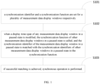
- one or more embodiments provide a method of synchronously displaying measurement data, which includes the following steps.
- a synchronization identifier and a synchronization function are set for a plurality of measurement data display windows respectively.
- step S 102 when a display time span of any measurement data display window in a paused state is modified, the synchronization function of other measurement data display windows in a paused state is called, and the synchronization identifier of the measurement data display window in a paused state is matched with the synchronization identifiers of other measurement data display windows in a paused state in the synchronization function, so as to achieve synchronization matching determination.
- step S103 if successful matching is achieved, synchronous operation is performed.
- the measurement data display windows include but not limited to a graphical window and a message information window and the like.
- the synchronization identifier is a string of information, which is used as an attribute of the measurement data display windows.
- the synchronization function is a callback function, which is defined by the base class of all measurement data display windows. Thus, each of the measurement data display windows can implement the callback function. Within the callback function, each measurement data display window determines how to perform synchronization on its own based on its own characteristics.
- a measurement data display window may be in a running state or a paused state.
- the running state When the running state is activated, the measurement data display window can continuously track and display the latest signal state.
- the paused state is activated, the measurement data display window will not track and display the latest signal state but maintain the current display, helping the user to analyze the signal data in the current display.
- the display time span includes two time points, which are a start time point and an end time point. If one of the time points is changed, it means the display time span is changed.
- the synchronous operation includes but not limited to the following action steps.
- a start time of the time axis of the current measurement data display window is set.
- step S202 an end time of the time axis of the current measurement data display window is set.
- step S203 the data display of the current measurement data display window is refreshed such that the current measurement data display window displays the data between the start time and the end time of the time axis.
- modifying the display time span of any measurement data display window in a paused state includes: triggering an event that affects the display time span; based on the event that affects the display time span, calculating a current display time span of the measurement data display window in a paused state; updating the display time span of the measurement data display window in a paused state to the current display time span.
- the event that affects the display time span is a trigger event.
- the trigger event specifically may include but not limited to a mouse event, a keyboard event and a program control event.
- the influence of the mouse event includes but not limited to: the left key of the mouse drags such that the display time span is translated leftward or rightward while the length of the display time span is unchanged; the wheel of the mouse scales up and down such that the display time span is offset leftward or rightward, while the length of the display time span is scaled up or down.
- the influence of the keyboard event includes but not limited to:
- the influence of the program control event includes but not limited to: calling the system API function "app.set_analysis_time_range", and introducing the two parameters, i.e. the start point of the display time span and the end point of the display time span to achieve automatic setting of the display time span.
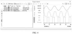
- the graphical window "EngineSpeed" in a software is in a paused state and the current display time span is 30 seconds to 40 seconds.
- a display time span modification event bound to the graphical window is triggered.
- the modified latest display time span is calculated firstly as a display time span with the start time point increased by 5 seconds and the end time point increased by 5 seconds, namely, the current display time span is modified to 35 seconds to 45 seconds; next, in the graphical window, the signal curve within the range of the display time span is updated as shown in FIG. 5 .
- a method of matching the synchronization identifier of the measurement data display window in a paused state with the synchronization identifiers of other measurement data display windows in a paused state in the synchronization function includes: determining whether the synchronization identifier of the measurement data display window in a paused state is identical to the synchronization identifiers of other measurement data display windows in a paused state, and if yes, the matching is achieved.
- the synchronization matching determination may compare the synchronization identifier of the graphical window A with the synchronization identifiers of the graphical windows B and C and find that the synchronization identifier of the graphical window A is equal to the synchronization identifier of the graphical window C but not equal to the synchronization identifier of the graphical window B.
- the graphical window C will be synchronized by the graphical window A but the graphical window B will not be synchronized.
- a method of performing synchronization operation includes:
- the initial display time span of the graphical window A is between the start time 1 second and the end time 3 seconds.
- the user modifies the display time span to one with the start time 2 seconds and the end time 6 seconds.
- the synchronization matching determination reads the synchronization identifier of the graphical window A and its latest current display time span and uses them as parameters to call the synchronization functions of the graphical windows B and C.
- the graphical window B and the graphical window C determine whether their own synchronization identifiers are same as that of the graphical window A respectively within the synchronization function, and the determination result is that it is different from the graphical window B but same as the graphical window C.
- the successfully-matched graphical window C modifies its own display time span to the current display time span transferred by the graphical window A, the one with the start time 2 seconds and the end time 6 seconds.
- synchronous operation is accomplished on the graphical window A and the graphical window C and then the synchronization process is ended.
- a method of determining the measurement data display window is in a paused state includes: determining whether a pause flag of the measurement data display window is true; if yes, the measurement data display window is determined in a paused state.
- a method of determining that the measurement data display window is in a paused state will be detailed below with a specific case.
- the variable associated with the button changes from false to true, which indicates the graphical window is in a paused state.
- the button is displayed as "run", and the user may click this button to continue measurement.
- the user uses the graphical window “EngineSpeed” and the message information window “EngineTrace” in a paused state to perform analysis on the vehicle bus.
- the synchronization identifiers of the two windows are "DEFAULT”.
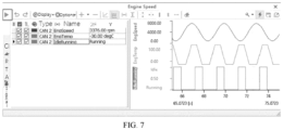
- the user may drag the graphical window by using the left key of the mouse to observe the change of the signal curve over time in the graphical window.
- start time point of the display time span for the drag is close to 67.6 seconds, and the end time point is close to 68 seconds, it is found that the state of the signal "IdleRunning” changes from “Idle” to "Running".
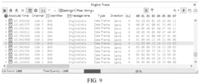
- the user hopes to view the values of other signals in the message where the signal "IdleRunning" is located at the time of change of the signal. As shown in FIG. 9 , at this time, the user switches to the message information window "EngineTrace". Since the window is also in a paused state and the synchronization identifier is identical to that of the graphical window "EngineSpeed", the display time span of the window is the same as the display time span of the graphical window "EngineSpeed”.
- the user can immediately position the change time of the signal "IdleRunning” by simply unfolding the message, one frame previous to the time of 67.9 seconds. It can be seen that the value of the signal “IdleRunning” at the time of 67.841980 seconds is “Idle” whereas the value of the signal at the time of 67.892935 is “Running", which indicates that the time of 67.892935 seconds is the change time of the signal. Thus, by unfolding other signals of the message where the signal is located at the time of 67.892935 seconds, the values of other signals of the message where the signal is located can be observed.
- one or more embodiments further provide a system for synchronously displaying measurement data, which includes:
- the system for synchronously displaying measurement data can be applied to the vehicle bus tool software as well as data collection and analysis of other debugging devices.
- a method of executing the system for synchronously displaying measurement data including:
- the method of synchronously displaying measurement data can be referred to the above detailed descriptions and will not be repeated herein.
- one or more embodiments further provide a system for synchronously displaying measurement data in a vehicle bus tool software, which includes:
- Computer instructions corresponding to the specific implementation functions of the synchronization setting module, the synchronization matching determination module and the synchronization executing module are stored in a computer readable storage medium and can be implemented in a computer device with reference to the contents of the above method of synchronously displaying measurement data and thus no redundant descriptions are made herein.
- One or more embodiments further provide an apparatus, which includes: at least one memory and at least one processor, where the memory stores at least one computer executable instruction which is executed by a processor to perform the method of synchronously displaying measurement data; the method of synchronously displaying measurement data includes: setting a synchronization identifier and a synchronization function for a plurality of measurement data display windows respectively; when a display time span of any measurement data display window in a paused state is modified, calling the synchronization function of other measurement data display windows in a paused state, and matching the synchronization identifier of the measurement data display window in a paused state with the synchronization identifiers of other measurement data display windows in a paused state in the synchronization function; if successfully matching, performing synchronization operation.
- the method of synchronously displaying measurement data includes: setting a synchronization identifier and a synchronization function for a plurality of measurement data display windows respectively; when a display time span of any measurement data display window in
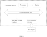
- the present electronic device includes: at least one processor, at least one readable storage medium (also called memory), at least one communication bus and at least one communication interface, where the processor, the readable storage medium and the communication interface communicate with each other via the communication bus; the readable storage medium is configured to store at least one program of executing the method of synchronously displaying measurement data, where the program cause the processor to perform the operations corresponding to the method of synchronously displaying measurement data; the method of synchronously displaying measurement data includes: setting a synchronization identifier and a synchronization function for a plurality of measurement data display windows respectively; when a display time span of any measurement data display window in a paused state is modified, calling the synchronization function of other measurement data display windows in a paused state, and matching the synchronization identifier of the measurement data display window in a paused state with the synchronization identifiers of other measurement data display windows in a paused state in the synchronization function; if successfully matching, performing
- the specific hardware structure of the computer device, the industrial personal computer and apparatus can also be used as one of the electronic devices.
- the structure as shown in FIG. 13 does not constitute a limitation on the electronic device; it can include fewer or more components than illustrated, or a combination of certain components, or a different arrangement of components.
- the communication interface may be RS232, RS485, USB interface or TYPE interface or the like, which may be connected with an external bus adapter.
- the communication interface may also include wired or wireless network interface.
- the network interface may optionally include wired interface and/or wireless interface (such as WI-FI interface, Bluetooth interface and the like), which is usually used to establish communication connection between the server and other computer devices.
- the readable storage medium or the computer readable storage medium includes at least one type of memories.
- the memory includes flash memory, harddisk drive, multimedia card, card type memory (e.g. SD memory or the like), magnetic memory, magnetic disk or compact disk or the like.
- the memory may be an internal storage unit in the computer device, for example, a harddisk drive of the computer device.
- the memory may also be an external storage device of the computer device, for example, a plug type hard disk drive, a smart media card (SMC), a secure digital (SD) card, a flash card or the like on the computer device.
- the memory may include both the internal storage unit in the computer device and the external storage device.
- the memory may be used to not only store an application software installed on the computer device and various types of data, for example, the codes of the computer programs and the like but also temporarily store data already output or to be output.
- the processor may be a central processing unit (CPU), a controller, a microcontroller, a microprocessor or another data processing chip, which is used to run the program codes in the memory or process the data, for example, execute the computer programs or the like.
- CPU central processing unit
- controller a controller
- microcontroller a microprocessor or another data processing chip, which is used to run the program codes in the memory or process the data, for example, execute the computer programs or the like.
- the communication bus may also be an input/output bus, which may be a Peripheral Component Interconnect (PCI) bus, or an Enhanced Industry Standard Architecture (EISA) bus or the like.
- the bus may include an address bus, a data bus and a control bus and the like.
- the computer device may also include a user interface, which may include a display, and an input unit, for example, a keyboard.
- the user interface may also include a standard wired interface and wireless interface.
- the display may be an LED display, a liquid crystal display, a touch liquid crystal display and an Organic Light-Emitting Diode (OLED) touch display and the like.
- the display may also be appropriately referred to as display screen or display unit for displaying information processed in the computer device as well as a visual user interface.
- the processor executes the programs to perform the steps in the embodiments of the method of synchronously displaying measurement data as shown in FIG. 1 , for example, the steps S101 to S103 shown in FIG. 1 .
- the processor executes the computer programs to implement the functions of the modules or units in the apparatus embodiments.
- One or more embodiments further provide a computer readable storage medium configured to store at least one program of executing any one of the above methods of synchronously displaying measurement data.
- One or more embodiments further provide a computer readable storage medium, storing at least one computer readable instruction, where the computer readable instruction is executed by at least one processor to perform the above method of synchronously displaying measurement data through the following steps: setting a synchronization identifier and a synchronization function for a plurality of measurement data display windows respectively; when a display time span of any measurement data display window in a paused state is modified, calling the synchronization function of other measurement data display windows in a paused state, and matching the synchronization identifier of the measurement data display window in a paused state with the synchronization identifiers of other measurement data display windows in a paused state in the synchronization function; if successfully matching, performing synchronization operation.
- a computer readable storage medium storing at least one computer readable instruction, where the computer readable instruction is executed by at least one processor to perform the above method of synchronously displaying measurement data through the following steps: setting a synchronization identifier and a synchronization function
- One or more embodiments provide a computer program product, including at least one computer program or instruction, where the computer program or instruction is executed on a computer to cause the computer to perform any one of the above methods of synchronously displaying measurement data.
- One or more embodiments provide a computer program product, including a computer readable storage medium storing computer readable program codes, where the computer readable program codes include at least one instruction which cause at least one processor or one or more computer devices to perform the operations of:
- these instructions can also cause at least one processor or one or more computer devices to perform the operations: modifying the display time span of any measurement data display window in a paused state includes: triggering an event that affects the display time span; based on the event that affects the display time span, calculating a current display time span of the measurement data display window in a paused state; updating the display time span of the measurement data display window in a paused state to the current display time span.
- these instructions can also cause at least one processor or one or more computer devices to perform the operations: the event that affects the display time span includes a mouse event, a keyboard event and a program control event.
- At least one processor or one or more computer devices can also be configured to perform the following steps: a method of matching the synchronization identifier of the measurement data display window in a paused state with the synchronization identifiers of other measurement data display windows in a paused state in the synchronization function includes: determining whether the synchronization identifier of the measurement data display window in a paused state is identical to the synchronization identifiers of other measurement data display windows in a paused state, and if yes, the matching is achieved.
- these instructions can also cause at least one processor or one or more computer devices to perform the operations: a method of performing synchronization operation includes: transferring the current display time span of any measurement data display window in a paused state as a parameter to the synchronization function of each of the successfully-matched measurement data display windows in a paused state; modifying, by each of the successfully-matched measurement data display windows, the display time span of the successfully-matched measurement data display window to the display time span carried in parameters of the corresponding synchronization function, namely, making the display time span of each of the successfully-matched measurement data display windows identical with the display time span of the measurement data display window in a paused state so as to achieve synchronization operation.
- these instructions can also cause at least one processor or one or more computer devices to perform the operations: a method of determining that the measurement data display window is in a paused state includes: determining whether a pause flag of the measurement data display window is true; if yes, the measurement data display window is determined in a paused state.
- these instructions can also cause at least one processor or one or more computer devices to perform the operations: the synchronization identifier is a string type.
- these instructions can also cause at least one processor or one or more computer devices to perform the following operations: the measurement data display window is a graphical window or a message information window.
- the bus adapter may be a Controller Area Network (CAN) bus adapter, a Controller Area Network Flexible Data Rate (CANFD) bus adapter, a Fast Local Interconnect Network (FastLIN) bus adapter, a Local Interconnect Network (LIN) bus adapter, an Ethernet bus adapter or a FlexRay bus adapter, and also may be one-to-multiple or multiple-to-multiple. In some other embodiments, no limitation is made to the specific implementation of the bus adapter.
- CAN Controller Area Network
- CANFD Controller Area Network Flexible Data Rate
- FastLIN Fast Local Interconnect Network
- LIN Local Interconnect Network
- Ethernet bus adapter or a FlexRay bus adapter an Ethernet bus adapter or a FlexRay bus adapter
- a plurality of pieces of measurement data are obtained from the ECU (Electronic Control Unit) by communicating with the debugging device, such as ECU and relevant systems, based on Unified Diagnostic Services (UDS) or Universal Measurement and Calibration Protocol (XCP) or CAN Calibration Protocol (CCP).
- UDS Unified Diagnostic Services
- XCP Universal Measurement and Calibration Protocol
- CCP CAN Calibration Protocol
- the debugging device in the vehicle field may specifically be a vehicular Electronic Control Unit (ECU) and its relevant system, for example, includes but not limited to: Electric Power Steering System (EPS), Anti-lock Braking System (ABS), Electronic Stability Control (ESC), vehicle engine management system and Battery Management System (BMS) and the like, which can be connected to the computer device via a bus to receive a plurality of pieces of measurement data.
- ECU Electronic Control Unit
- EPS Electric Power Steering System
- ABS Anti-lock Braking System
- ESC Electronic Stability Control
- BMS Battery Management System
- each block in the flowcharts or block diagrams may represent one module, one program fragment or one part of codes.
- the module, the program fragment or the part of codes includes one or more executable instructions for implementing the specified logic functions.
- the functions indicated in the blocks may also be performed in a sequence different from that indicated in the drawings.
- each block in the block diagrams and/or flowcharts and the combinations of the blocks in the block diagrams and/or flowcharts may be implemented by a dedicated hardware-based system for executing specified functions or actions, or by combination of dedicated hardware and computer instructions.
- the functional modules in the embodiments of the present disclosure can be integrated into one independent part, or exist as separate modules or two or more of the modules are integrated into one independent part.
- the computer software product is stored in one storage medium which includes several instructions to enable one computer device (for example, a personal computer, a server, or a network device or the like) to perform all or part of the steps of the method of each of the embodiments of the present disclosure.
Landscapes
- Engineering & Computer Science (AREA)
- Theoretical Computer Science (AREA)
- General Engineering & Computer Science (AREA)
- Physics & Mathematics (AREA)
- General Physics & Mathematics (AREA)
- Quality & Reliability (AREA)
- Human Computer Interaction (AREA)
- Software Systems (AREA)
- Computer Vision & Pattern Recognition (AREA)
- Computer Hardware Design (AREA)
- User Interface Of Digital Computer (AREA)
- Controls And Circuits For Display Device (AREA)
- Testing, Inspecting, Measuring Of Stereoscopic Televisions And Televisions (AREA)
- Digital Computer Display Output (AREA)
Applications Claiming Priority (2)
| Application Number | Priority Date | Filing Date | Title |
|---|---|---|---|
| US18/512,083 US12547363B2 (en) | 2023-11-17 | 2023-11-17 | System for synchronously displaying measurement data and execution method thereof |
| CN202311780520.4A CN117743480B (zh) | 2023-11-17 | 2023-12-22 | 测量数据同步显示方法、装置及计算机可读存储介质 |
Publications (1)
| Publication Number | Publication Date |
|---|---|
| EP4557067A1 true EP4557067A1 (de) | 2025-05-21 |
Family
ID=90717415
Family Applications (1)
| Application Number | Title | Priority Date | Filing Date |
|---|---|---|---|
| EP24167951.3A Pending EP4557067A1 (de) | 2023-11-17 | 2024-03-30 | Verfahren und vorrichtung zur synchronen anzeige von messdaten und computerlesbares speichermedium |
Country Status (5)
| Country | Link |
|---|---|
| EP (1) | EP4557067A1 (de) |
| JP (2) | JP7721183B2 (de) |
| KR (1) | KR20250072849A (de) |
| CA (1) | CA3255173A1 (de) |
| MX (1) | MX2024014275A (de) |
Citations (4)
| Publication number | Priority date | Publication date | Assignee | Title |
|---|---|---|---|---|
| US20110181608A1 (en) * | 2010-01-22 | 2011-07-28 | Chandra Sunkara | Method, system, and storage media for global synchronization of time |
| US20170069147A1 (en) * | 2013-10-16 | 2017-03-09 | Smartdrive Systems, Inc. | Vehicle event playback apparatus and methods |
| US20210255757A1 (en) * | 2016-10-05 | 2021-08-19 | Snap-On Incorporated | System and Method for Providing an Interactive Vehicle Diagnostic Display |
| US20220180676A1 (en) * | 2019-04-08 | 2022-06-09 | Volvo Truck Corporation | System for analyzing data in a vehicle |
Family Cites Families (3)
| Publication number | Priority date | Publication date | Assignee | Title |
|---|---|---|---|---|
| US6940039B2 (en) | 2003-12-22 | 2005-09-06 | Lincoln Global, Inc. | Quality control module for tandem arc welding |
| JP2010072829A (ja) | 2008-09-17 | 2010-04-02 | Toyota Motor Corp | 信号取得システムおよび信号取得装置 |
| JP6559982B2 (ja) | 2015-03-13 | 2019-08-14 | 埼広エンジニヤリング株式会社 | 記録計及び記録計を備えた測定システム |
-
2024
- 2024-03-30 EP EP24167951.3A patent/EP4557067A1/de active Pending
- 2024-04-17 KR KR1020240051754A patent/KR20250072849A/ko active Pending
- 2024-06-30 JP JP2024105833A patent/JP7721183B2/ja active Active
- 2024-09-24 CA CA3255173A patent/CA3255173A1/en active Pending
- 2024-11-15 MX MX2024014275A patent/MX2024014275A/es unknown
-
2025
- 2025-07-23 JP JP2025123174A patent/JP2025160303A/ja active Pending
Patent Citations (4)
| Publication number | Priority date | Publication date | Assignee | Title |
|---|---|---|---|---|
| US20110181608A1 (en) * | 2010-01-22 | 2011-07-28 | Chandra Sunkara | Method, system, and storage media for global synchronization of time |
| US20170069147A1 (en) * | 2013-10-16 | 2017-03-09 | Smartdrive Systems, Inc. | Vehicle event playback apparatus and methods |
| US20210255757A1 (en) * | 2016-10-05 | 2021-08-19 | Snap-On Incorporated | System and Method for Providing an Interactive Vehicle Diagnostic Display |
| US20220180676A1 (en) * | 2019-04-08 | 2022-06-09 | Volvo Truck Corporation | System for analyzing data in a vehicle |
Also Published As
| Publication number | Publication date |
|---|---|
| KR20250072849A (ko) | 2025-05-26 |
| MX2024014275A (es) | 2025-06-02 |
| JP2025160303A (ja) | 2025-10-22 |
| JP2025082794A (ja) | 2025-05-29 |
| JP7721183B2 (ja) | 2025-08-12 |
| CA3255173A1 (en) | 2025-10-30 |
Similar Documents
| Publication | Publication Date | Title |
|---|---|---|
| EP3432463B1 (de) | Motorsteuerungssystem, motorsteuerungsvorrichtung, programm und aufzeichnungsmedium | |
| CN113489653A (zh) | 报文发送方法、装置以及计算机设备 | |
| CN114936107A (zh) | 车辆整车数据校验方法、装置、电子设备及存储介质 | |
| EP4557067A1 (de) | Verfahren und vorrichtung zur synchronen anzeige von messdaten und computerlesbares speichermedium | |
| US12547363B2 (en) | System for synchronously displaying measurement data and execution method thereof | |
| US20250166253A1 (en) | Method and apparatus for synchronously displaying measurement data and computer readable storage medium | |
| RU2847437C1 (ru) | Способ, электронное устройство и система для синхронного отображения данных измерений и считываемый компьютером носитель данных | |
| CN115277261A (zh) | 基于工控网络病毒的异常机器智能识别方法、装置、设备 | |
| WO2026021046A1 (zh) | 数据获取方法、装置、存储介质及程序产品 | |
| CN117608894B (zh) | 日志的存储方法、装置、计算机设备及存储介质 | |
| CN120234375A (zh) | 测量数据同步显示方法及系统、计算机程序产品 | |
| CN113448748B (zh) | 一种通过消息驱动的刷新方法及刷新系统 | |
| US12517630B2 (en) | Association system of panel controls for calibration signals, and calibration system and method | |
| EP3637262A1 (de) | Verifizierungsvorrichtung für fahrzeugsteuerungsvorrichtung und fahrzeugsteuerungsvorrichtung | |
| US20250231677A1 (en) | Association method of panel controls for calibration signals, computer readable storage medium and electronic device | |
| EP4586072A1 (de) | Verfahren zur zuordnung von kalibrierungssignalen zu plattensteuerungen, computerlesbares speichermedium und elektronische vorrichtung | |
| RU2847321C1 (ru) | Способ, электронное устройство и система связывания калибровочных сигналов с элементами управления панели и машиночитаемый носитель данных | |
| US12602153B2 (en) | Signal tracking and observation system and method | |
| US20250173056A1 (en) | Signal tracking and observation method, computer readable storage medium and electronic device | |
| JP2017129931A (ja) | トレースデータ編集装置及び方法 | |
| EP4589463A1 (de) | Adaptives aktualisierungsverfahren von signaldaten für bussimulations- und testverfahren | |
| CN115827721A (zh) | 实时数据的统计方法、装置、电子设备及存储介质 | |
| CN115756459A (zh) | 基于数字信号处理器的监控界面构建方法和装置 | |
| CN121638186A (zh) | 信息交互方法、装置、电子设备、存储介质及程序产品 | |
| JP3105105B2 (ja) | 電子制御ユニットのモニタ装置 |
Legal Events
| Date | Code | Title | Description |
|---|---|---|---|
| PUAI | Public reference made under article 153(3) epc to a published international application that has entered the european phase |
Free format text: ORIGINAL CODE: 0009012 |
|
| STAA | Information on the status of an ep patent application or granted ep patent |
Free format text: STATUS: REQUEST FOR EXAMINATION WAS MADE |
|
| 17P | Request for examination filed |
Effective date: 20240330 |
|
| AK | Designated contracting states |
Kind code of ref document: A1 Designated state(s): AL AT BE BG CH CY CZ DE DK EE ES FI FR GB GR HR HU IE IS IT LI LT LU LV MC ME MK MT NL NO PL PT RO RS SE SI SK SM TR |