EP4557446A2 - Wiederaufladbare batterie und wiederaufladbares batteriemodul - Google Patents
Wiederaufladbare batterie und wiederaufladbares batteriemodul Download PDFInfo
- Publication number
- EP4557446A2 EP4557446A2 EP24187822.2A EP24187822A EP4557446A2 EP 4557446 A2 EP4557446 A2 EP 4557446A2 EP 24187822 A EP24187822 A EP 24187822A EP 4557446 A2 EP4557446 A2 EP 4557446A2
- Authority
- EP
- European Patent Office
- Prior art keywords
- electrode
- secondary battery
- case
- reference electrode
- terminal
- Prior art date
- Legal status (The legal status is an assumption and is not a legal conclusion. Google has not performed a legal analysis and makes no representation as to the accuracy of the status listed.)
- Pending
Links
Images


Classifications
-
- G—PHYSICS
- G01—MEASURING; TESTING
- G01N—INVESTIGATING OR ANALYSING MATERIALS BY DETERMINING THEIR CHEMICAL OR PHYSICAL PROPERTIES
- G01N27/00—Investigating or analysing materials by the use of electric, electrochemical, or magnetic means
- G01N27/26—Investigating or analysing materials by the use of electric, electrochemical, or magnetic means by investigating electrochemical variables; by using electrolysis or electrophoresis
- G01N27/28—Electrolytic cell components
- G01N27/30—Electrodes, e.g. test electrodes; Half-cells
-
- H—ELECTRICITY
- H01—ELECTRIC ELEMENTS
- H01M—PROCESSES OR MEANS, e.g. BATTERIES, FOR THE DIRECT CONVERSION OF CHEMICAL ENERGY INTO ELECTRICAL ENERGY
- H01M50/00—Constructional details or processes of manufacture of the non-active parts of electrochemical cells other than fuel cells, e.g. hybrid cells
- H01M50/50—Current conducting connections for cells or batteries
- H01M50/569—Constructional details of current conducting connections for detecting conditions inside cells or batteries, e.g. details of voltage sensing terminals
-
- G—PHYSICS
- G01—MEASURING; TESTING
- G01N—INVESTIGATING OR ANALYSING MATERIALS BY DETERMINING THEIR CHEMICAL OR PHYSICAL PROPERTIES
- G01N27/00—Investigating or analysing materials by the use of electric, electrochemical, or magnetic means
- G01N27/26—Investigating or analysing materials by the use of electric, electrochemical, or magnetic means by investigating electrochemical variables; by using electrolysis or electrophoresis
- G01N27/416—Systems
-
- H—ELECTRICITY
- H01—ELECTRIC ELEMENTS
- H01M—PROCESSES OR MEANS, e.g. BATTERIES, FOR THE DIRECT CONVERSION OF CHEMICAL ENERGY INTO ELECTRICAL ENERGY
- H01M10/00—Secondary cells; Manufacture thereof
- H01M10/05—Accumulators with non-aqueous electrolyte
- H01M10/058—Construction or manufacture
-
- H—ELECTRICITY
- H01—ELECTRIC ELEMENTS
- H01M—PROCESSES OR MEANS, e.g. BATTERIES, FOR THE DIRECT CONVERSION OF CHEMICAL ENERGY INTO ELECTRICAL ENERGY
- H01M10/00—Secondary cells; Manufacture thereof
- H01M10/42—Methods or arrangements for servicing or maintenance of secondary cells or secondary half-cells
- H01M10/425—Structural combination with electronic components, e.g. electronic circuits integrated to the outside of the casing
-
- H—ELECTRICITY
- H01—ELECTRIC ELEMENTS
- H01M—PROCESSES OR MEANS, e.g. BATTERIES, FOR THE DIRECT CONVERSION OF CHEMICAL ENERGY INTO ELECTRICAL ENERGY
- H01M10/00—Secondary cells; Manufacture thereof
- H01M10/42—Methods or arrangements for servicing or maintenance of secondary cells or secondary half-cells
- H01M10/44—Methods for charging or discharging
-
- H—ELECTRICITY
- H01—ELECTRIC ELEMENTS
- H01M—PROCESSES OR MEANS, e.g. BATTERIES, FOR THE DIRECT CONVERSION OF CHEMICAL ENERGY INTO ELECTRICAL ENERGY
- H01M10/00—Secondary cells; Manufacture thereof
- H01M10/42—Methods or arrangements for servicing or maintenance of secondary cells or secondary half-cells
- H01M10/48—Accumulators combined with arrangements for measuring, testing or indicating the condition of cells, e.g. the level or density of the electrolyte
-
- H—ELECTRICITY
- H01—ELECTRIC ELEMENTS
- H01M—PROCESSES OR MEANS, e.g. BATTERIES, FOR THE DIRECT CONVERSION OF CHEMICAL ENERGY INTO ELECTRICAL ENERGY
- H01M50/00—Constructional details or processes of manufacture of the non-active parts of electrochemical cells other than fuel cells, e.g. hybrid cells
- H01M50/10—Primary casings; Jackets or wrappings
- H01M50/102—Primary casings; Jackets or wrappings characterised by their shape or physical structure
- H01M50/103—Primary casings; Jackets or wrappings characterised by their shape or physical structure prismatic or rectangular
-
- H—ELECTRICITY
- H01—ELECTRIC ELEMENTS
- H01M—PROCESSES OR MEANS, e.g. BATTERIES, FOR THE DIRECT CONVERSION OF CHEMICAL ENERGY INTO ELECTRICAL ENERGY
- H01M50/00—Constructional details or processes of manufacture of the non-active parts of electrochemical cells other than fuel cells, e.g. hybrid cells
- H01M50/10—Primary casings; Jackets or wrappings
- H01M50/147—Lids or covers
- H01M50/148—Lids or covers characterised by their shape
- H01M50/15—Lids or covers characterised by their shape for prismatic or rectangular cells
-
- H—ELECTRICITY
- H01—ELECTRIC ELEMENTS
- H01M—PROCESSES OR MEANS, e.g. BATTERIES, FOR THE DIRECT CONVERSION OF CHEMICAL ENERGY INTO ELECTRICAL ENERGY
- H01M50/00—Constructional details or processes of manufacture of the non-active parts of electrochemical cells other than fuel cells, e.g. hybrid cells
- H01M50/10—Primary casings; Jackets or wrappings
- H01M50/172—Arrangements of electric connectors penetrating the casing
- H01M50/174—Arrangements of electric connectors penetrating the casing adapted for the shape of the cells
- H01M50/176—Arrangements of electric connectors penetrating the casing adapted for the shape of the cells for prismatic or rectangular cells
-
- H—ELECTRICITY
- H01—ELECTRIC ELEMENTS
- H01M—PROCESSES OR MEANS, e.g. BATTERIES, FOR THE DIRECT CONVERSION OF CHEMICAL ENERGY INTO ELECTRICAL ENERGY
- H01M50/00—Constructional details or processes of manufacture of the non-active parts of electrochemical cells other than fuel cells, e.g. hybrid cells
- H01M50/50—Current conducting connections for cells or batteries
- H01M50/543—Terminals
- H01M50/547—Terminals characterised by the disposition of the terminals on the cells
- H01M50/55—Terminals characterised by the disposition of the terminals on the cells on the same side of the cell
-
- H—ELECTRICITY
- H01—ELECTRIC ELEMENTS
- H01M—PROCESSES OR MEANS, e.g. BATTERIES, FOR THE DIRECT CONVERSION OF CHEMICAL ENERGY INTO ELECTRICAL ENERGY
- H01M50/00—Constructional details or processes of manufacture of the non-active parts of electrochemical cells other than fuel cells, e.g. hybrid cells
- H01M50/50—Current conducting connections for cells or batteries
- H01M50/543—Terminals
- H01M50/552—Terminals characterised by their shape
- H01M50/553—Terminals adapted for prismatic, pouch or rectangular cells
-
- H—ELECTRICITY
- H01—ELECTRIC ELEMENTS
- H01M—PROCESSES OR MEANS, e.g. BATTERIES, FOR THE DIRECT CONVERSION OF CHEMICAL ENERGY INTO ELECTRICAL ENERGY
- H01M10/00—Secondary cells; Manufacture thereof
- H01M10/42—Methods or arrangements for servicing or maintenance of secondary cells or secondary half-cells
- H01M10/425—Structural combination with electronic components, e.g. electronic circuits integrated to the outside of the casing
- H01M2010/4271—Battery management systems including electronic circuits, e.g. control of current or voltage to keep battery in healthy state, cell balancing
-
- Y—GENERAL TAGGING OF NEW TECHNOLOGICAL DEVELOPMENTS; GENERAL TAGGING OF CROSS-SECTIONAL TECHNOLOGIES SPANNING OVER SEVERAL SECTIONS OF THE IPC; TECHNICAL SUBJECTS COVERED BY FORMER USPC CROSS-REFERENCE ART COLLECTIONS [XRACs] AND DIGESTS
- Y02—TECHNOLOGIES OR APPLICATIONS FOR MITIGATION OR ADAPTATION AGAINST CLIMATE CHANGE
- Y02E—REDUCTION OF GREENHOUSE GAS [GHG] EMISSIONS, RELATED TO ENERGY GENERATION, TRANSMISSION OR DISTRIBUTION
- Y02E60/00—Enabling technologies; Technologies with a potential or indirect contribution to GHG emissions mitigation
- Y02E60/10—Energy storage using batteries
-
- Y—GENERAL TAGGING OF NEW TECHNOLOGICAL DEVELOPMENTS; GENERAL TAGGING OF CROSS-SECTIONAL TECHNOLOGIES SPANNING OVER SEVERAL SECTIONS OF THE IPC; TECHNICAL SUBJECTS COVERED BY FORMER USPC CROSS-REFERENCE ART COLLECTIONS [XRACs] AND DIGESTS
- Y02—TECHNOLOGIES OR APPLICATIONS FOR MITIGATION OR ADAPTATION AGAINST CLIMATE CHANGE
- Y02P—CLIMATE CHANGE MITIGATION TECHNOLOGIES IN THE PRODUCTION OR PROCESSING OF GOODS
- Y02P70/00—Climate change mitigation technologies in the production process for final industrial or consumer products
- Y02P70/50—Manufacturing or production processes characterised by the final manufactured product
Definitions
- aspects of embodiments of the present disclosure relate to a rechargeable battery and a rechargeable battery module.
- a secondary battery generally includes an electrode assembly composed of a positive electrode and a negative electrode, a case accommodating the electrode assembly, and electrode terminals connected to the electrode assembly.
- a secondary (or rechargeable) battery module may include a battery management system.
- the battery management system is a system that monitors a battery state, and performs diagnosis and control, communication, and protection functions. For example, the battery management system may monitor and manage a voltage, a temperature, and a current of each secondary battery cell included in the secondary battery module to ensure their normal operation, and may detect insulation and short circuit conditions.
- a battery management system may only detect the voltage of the secondary battery cell (e.g., a difference between a positive electrode potential value and a negative electrode potential value), and thus, an accurate potential value of the positive electrode or an accurate potential value of the negative electrode may not be identified. As a result, the early detection of an abnormal state of the secondary battery cell may not be achieved in a case where the negative electrode potential value falls below zero, which may indicate that the secondary battery cell is in the abnormal state.
- the voltage of the secondary battery cell e.g., a difference between a positive electrode potential value and a negative electrode potential value
- Embodiments of the present disclosure may be directed to a three-electrode secondary battery including a reference electrode for accurately monitoring the secondary battery for abnormalities, and a secondary battery module including the secondary battery.
- a secondary battery includes: an electrode assembly including: a first electrode; a second electrode; and a separator between the first electrode and the second electrode; a case having an opening at one or more sides to accommodate the electrode assembly in the case through the opening; one or more cap plates sealing the opening at the one or more sides of the case, respectively; and a reference electrode located in a void volume inside the case.
- the void volume may be located inside the case between one of the one or more cap plates and the electrode assembly, and the reference electrode may be located in the void volume inside the case between the one of the one or more cap plates and the electrode assembly.
- the reference electrode may be spaced from the electrode assembly.
- the case may have a prismatic shape.
- the one or more sides of the case having the opening may include opposite lateral sides having side openings
- the one or more cap plates may include two side cap plates sealing the side openings at the opposite lateral sides of the case, respectively.
- the two side cap plates may include a first side cap plate and a second side cap plate.
- a first terminal electrically connected to the first electrode may be coupled to the first side cap plate
- a second terminal electrically connected with the second electrode may be coupled to the second side cap plate
- a reference electrode terminal electrically connected with the reference electrode may be coupled to either the first side cap plate or the second side cap plate.
- the first electrode may be electrically connected to the first terminal through a first current collector located between the electrode assembly and the first side cap plate
- the second electrode may be electrically connected to the second terminal through a second current collector located between the electrode assembly and the second side cap plate
- the reference electrode may be electrically connected to the reference electrode terminal through a reference electrode current collector.
- the reference electrode and the reference electrode current collector may be located between the electrode assembly and the first side cap plate, or may be located between the electrode assembly and the second side cap plate.
- the one or more sides of the case having the opening may include an upper side of the case having the opening, and the one or more cap plates may include one cap plate sealing the opening at the upper side of the case.
- a first terminal electrically connected with the first electrode, a second terminal electrically connected with the second electrode, and a reference electrode terminal electrically connected with the reference electrode may be coupled to the one cap plate.
- the reference electrode terminal may be located between the first terminal and the second terminal.
- the void volume may be located between the electrode assembly and the one cap plate.
- the first electrode may be electrically connected to the first terminal through a first current collector
- the second electrode may be electrically connected to the second terminal through a second current collector
- the reference electrode may be electrically connected to the reference electrode terminal through a reference electrode current collector.
- the reference electrode and the reference electrode current collector may be located between the first current collector and the second current collector in the void volume between the electrode assembly and the one cap plate.
- a secondary battery module includes a cell stack including a plurality of battery cells located along one direction, the plurality of battery cells including one or more secondary batteries as defined above or below, i.e. each including: an electrode assembly including: a first electrode; a second electrode; and a separator between the first electrode and the second electrode; a case having an opening at one or more sides to accommodate the electrode assembly in the case through the opening; one or more cap plates sealing the opening at the one or more sides of the case, respectively; and a reference electrode located in a void volume inside the case.
- the secondary battery module may further include a battery management system electrically connected to the one or more secondary batteries, and configured to calculate at least one of a potential value of the first electrode or a potential value of the second electrode, by detecting at least one of a voltage between the reference electrode and the first electrode or a voltage between the reference electrode and the second electrode.
- a battery management system electrically connected to the one or more secondary batteries, and configured to calculate at least one of a potential value of the first electrode or a potential value of the second electrode, by detecting at least one of a voltage between the reference electrode and the first electrode or a voltage between the reference electrode and the second electrode.
- the one or more secondary batteries may include two or more secondary batteries, at least one of the two or more secondary batteries may be located at an outermost side of the cell stack, and at least another one of the two or more secondary batteries may be located at a center of the cell stack.
- the reference electrode may be disposed in the void volume inside the case. Accordingly, the three-electrode secondary battery including the reference electrode may be implemented, without occupying an additional volume (e.g., without a decrease in energy density).
- a secondary battery comprising:
- a secondary battery module that includes a cell stack including a plurality of battery cells arranged in one direction.
- the cell stack may include one or more secondary batteries according to one or more embodiments of the present disclosure.
- the secondary battery module described above may further include a battery management system electrically connected to the one or more secondary batteries. Further, the battery management system may calculate at least one of a potential value of the first electrode or a potential value of the second electrode by detecting at least one of a voltage between the reference electrode and the first electrode or a voltage between the reference electrode and the second electrode.
- the cell stack may include two or more secondary batteries, at least one of the two or more secondary batteries may be disposed at an outermost side of the cell stack, and at least one of the two or more secondary batteries may be disposed at a center of the cell stack.
- a specific process order may be different from the described order.
- two consecutively described processes may be performed at the same or substantially at the same time, or may be performed in an order opposite to the described order.
- first,” “second,” “third,” etc. may be used herein to describe various elements, components, regions, layers and/or sections, these elements, components, regions, layers and/or sections should not be limited by these terms. These terms are used to distinguish one element, component, region, layer or section from another element, component, region, layer or section. Thus, a first element, component, region, layer or section described below could be termed a second element, component, region, layer or section, without departing from the scope of the present disclosure.
- the expression "A and/or B” denotes A, B, or A and B. Expressions such as “at least one of,” when preceding a list of elements, modify the entire list of elements and do not modify the individual elements of the list. For example, the expression “at least one of a, b, or c,” “at least one of a, b, and c,” and “at least one selected from the group consisting of a, b, and c" indicates only a, only b, only c, both a and b, both a and c, both b and c, all of a, b, and c, or variations thereof.
- the term “substantially,” “about,” and similar terms are used as terms of approximation and not as terms of degree, and are intended to account for the inherent variations in measured or calculated values that would be recognized by those of ordinary skill in the art. Further, the use of “may” when describing embodiments of the present disclosure refers to “one or more embodiments of the present disclosure.” As used herein, the terms “use,” “using,” and “used” may be considered synonymous with the terms “utilize,” “utilizing,” and “utilized,” respectively.
- any numerical ranges disclosed and/or recited herein is intended to include all sub-ranges of the same numerical precision subsumed within the recited range.
- a range of "1.0 to 10.0" is intended to include all subranges between (and including) the recited minimum value of 1.0 and the recited maximum value of 10.0, or in other words, having a minimum value equal to or greater than 1.0 and a maximum value equal to or less than 10.0, such as, for example, 2.4 to 7.6.
- Any maximum numerical limitations recited herein is intended to include all lower numerical limitations subsumed therein, and any minimum numerical limitations recited herein is intended to include all higher numerical limitations subsumed therein.
- references to two compared elements, features, etc. as being “the same” may mean that they are “substantially the same”.
- the phrase “substantially the same” may include a case having a deviation that is considered low in the art, for example, a deviation of 5% or less.
- a certain parameter when referred to as being uniform in a given region, it may mean that it is uniform in terms of an average
- a battery pack includes at least one battery module, and a pack housing having an accommodation space in which the at least one battery module is accommodated.
- the battery module may include a plurality of battery cells and a module housing.
- the battery cells may be accommodated inside the module housing in a stacked form (e.g., stacked arrangement or configuration).
- Each battery cell may have a positive electrode terminal and a negative electrode terminal, and may be a circular type, a prismatic type, or a pouch type according to the shape of the battery.
- a battery cell may also be referred to as a secondary battery, a battery, or a cell.
- one cell stack may constitute one module stacked in place of the battery module.
- the cell stack may be accommodated in an accommodation space of the pack housing, or may be accommodated in an accommodation space partitioned by a frame, a partition wall, and the like.
- the battery cell may generate a large amount of heat during charging/discharging.
- the generated heat may be accumulated in the battery cell, thereby accelerating the deterioration of the battery cell.
- the battery pack may further include a cooling member to remove the generated heat, and thereby, suppress deterioration of the battery cell.
- the cooling member may be provided at the bottom of the accommodation space at where the battery cell is provided, but the present disclosure is not limited thereto, and the cooling member may be provided at the top or the side depending on the battery pack.
- Exhaust gas generated inside the battery cell under abnormal operating conditions also known as thermal runaway or thermal events, may be discharged to the outside of the battery cell.
- the battery pack or the battery module may include an exhaust port for discharging the exhaust gas to prevent or reduce damage to the battery pack or the battery module by the exhaust gas.
- the battery pack may include a battery, and a battery management system (BMS) for managing the battery.
- the battery management system may include a detection device, a balancing device, and a control device.
- the battery module may include a plurality of cells that are connected to each other in series and/or parallel. A plurality of battery modules may be connected to each other in series and/or in parallel.
- the detection device may detect a state of a battery (e.g., a voltage, a current, a temperature, and/or the like) to output state information indicating the state of the battery.
- the detection device may detect the voltage of each cell constituting the battery or of each battery module.
- the detection device may detect current flowing through each battery module constituting the battery module or the battery pack.
- the detection device may also detect the temperature of a cell and/or a module on at least one point of the battery and/or an ambient temperature.
- the balancing device may perform a balancing operation of a battery module and/or cells constituting the battery module.
- the control device may receive state information (e.g., a voltage, a current, a temperature, and/or the like) of the battery module from the detection device.
- the control device may monitor and calculate the state of the battery module (e.g., the voltage, the current, the temperature, a state of charge (SOC), a life span (e.g., state of health (SOH)), and/or the like) on the basis of the state information received from the detection device.
- state information e.g., a voltage, a current, a temperature, and/or the like
- SOC state of charge
- SOH state of health
- control device may perform a control function (e.g., a temperature control, a balancing control, a charge/discharge control, and/or the like) and a protection function (e.g., over-discharge, over-charge, over-current protection, short circuit, a fire extinguishing function, and/or the like).
- control device may perform a wired or wireless communication function with an external device of the battery pack (e.g., a higher level controller or a vehicle, a charger, a power conversion system, and/or the like).
- the control device may control charging/discharging operations and a protection operation of the battery.
- the control device may include a charge/discharge control unit (e.g., a charge/discharge control circuit), a balancing control unit (e.g., a balancing control circuit), and/or a protection unit (e.g., a protection circuit).
- a charge/discharge control unit e.g., a charge/discharge control circuit
- balancing control unit e.g., a balancing control circuit
- a protection unit e.g., a protection circuit
- the battery management system is a system that monitors the battery state, and performs diagnosis and control, communication, and protection functions.
- the battery management system may calculate the charge/discharge state, may calculate battery life or state of health (SOH), a cut off, as necessary, battery power (e.g., a relay control), control thermal management (e.g., cooling, heating, and/or the like), perform a high-voltage interlock function, and/or may detect and/or calculate insulation and short circuit conditions.
- SOH state of health
- control thermal management e.g., cooling, heating, and/or the like
- a relay may be a mechanical contactor that is turned on and off by the magnetic force of a coil or a semiconductor switch, such as a metal oxide semiconductor field effect transistor (MOSFET).
- MOSFET metal oxide semiconductor field effect transistor
- the relay control has a function of cutting off the power supply from the battery if (e.g., when) a problem occurs in the vehicle and/or the battery system, and may include one or more relays and pre-charge relays at the positive terminal and the negative terminal, respectively.
- the pre-charge relay may be operated before connecting the main relay, and the pre-charge resistor may be connected.
- the high-voltage interlock is a circuit that uses a small signal to detect whether or not all high-voltage parts of the entire vehicle system are connected, and may have a function of forcibly opening a relay if (e.g., when) an opening occurs at even one location on the entire loop.
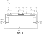
- FIG. 1 is a front view illustrating an example of a secondary battery 100 according to one or more embodiments of the present disclosure.
- the secondary battery 100 may include at least one electrode assembly 110 having a structure in which a positive electrode and a negative electrode are wound with a separator, which is an insulator, interposed between the positive electrode and the negative electrode.
- the secondary battery 100 may further include a case 120 accommodating the electrode assembly 110 therein, and a cap plate 130 connected to (e.g., coupled to or attached to) one side of the case 120 that is open.
- the secondary battery 100 shown in FIG. 1 may be an example type of battery cell.
- Each of the positive electrode and the negative electrode may include a coating region where an active material is coated onto a current collector, and an uncoated region where the active material is not coated onto the current collector.
- the current collector may be formed with a thin plate of a metal foil.
- the positive electrode and the negative electrode may be rolled up with the separator, which is the insulator, interposed therebetween.
- the electrode assembly 110 may have a structure in which a plurality of sheet-type positive and negative electrodes are stacked in an alternating manner, with separators interposed therebetween.
- the case 120 may form an entire exterior of the secondary battery 100, and may include (e.g., may be made of) a conductive metal, such as aluminum, an aluminum alloy, or nickel-plated steel.
- the case 120 may provide a space in which the electrode assembly 110 is accommodated.
- the case 120 may be of a prismatic shape.
- the secondary battery 100 may be a prismatic secondary battery.
- the cap plate 130 may be engaged with the one open side of the case 120 to seal the case 120.
- the case 120 and the cap plate 130 may include (e.g., may be made of) a conductive material.
- the case 120 may have an opening at an upper side thereof, and the cap plate 130 may seal and cover the upper opening of the case 120.
- the case 120 may have a vent unit (e.g., a vent) that is formed with a notch at the bottom portion or the side portion of the case 120.
- a positive electrode terminal 140 and a negative electrode terminal 150 that are electrically connected to the positive electrode and the negative electrode, respectively, may be connected to (e.g., coupled to or attached to) the cap plate 130.
- the positive and negative electrode terminals 140 and 150 may be passed through the cap plate 130, and may be protruded outside.
- the positive electrode and the positive electrode terminal 140 may be electrically connected to each other through a positive electrode current collector 144.
- the positive electrode current collector 144 may electrically connect the positive electrode with the positive electrode terminal 140 through a contact with a positive electrode uncoated region or a positive electrode tab 142 extending from or coupled to the positive electrode uncoated region.
- the negative electrode and the negative electrode terminal 150 may be electrically connected to each other through a negative electrode current collector 154.
- the negative electrode current collector 154 may electrically connect the negative electrode with the negative electrode terminal 150 through a contact with a negative electrode uncoated region or the negative electrode tab 152 extending from or connected to (e.g., coupled to or attached to) the negative electrode uncoated region.
- the secondary battery 100 may further include a reference electrode 162.
- the reference electrode 162 may include (e.g., may be composed of) a suitable material having a constant potential value, which may be determined based on the configuration (e.g., a type of the positive electrode, a type of the negative electrode, a type of an electrolyte, and/or the like) of the secondary battery 100.
- the reference electrode 162 may include, but is not limited to, a lithium metal, a sodium metal, a potassium metal, platinum, LiFePO 4 , Li 4 Tl 15 O 12 , or the like.
- the reference electrode 162 may be a lithium metal, a metal oxide containing lithium (e.g., LiFePO 4 , L 14 Tl 15 O 12 , and/or the like), or the like.
- the reference electrode 162 may maintain or substantially maintain a potential value of 0 V.
- the reference electrode 162 maintains or substantially maintains a constant potential value
- an accurate potential value of the positive electrode or an accurate potential value of the negative electrode may be calculated. Accordingly, it may be possible to accurately monitor the abnormality of the secondary battery 100, and also, to detect a soft short in the secondary battery 100.
- the reference electrode 162 may be disposed separately from the electrode assembly 110 in a void volume inside the case 120. In an embodiment, the reference electrode 162 may be disposed in the void volume inside the case 120 between the electrode assembly 110 and the cap plate 130. Accordingly, a three-electrode secondary battery 100 including the reference electrode 162 may be implemented without occupying an additional volume (e.g., without a decrease in the energy density).
- a reference electrode terminal 160 which is electrically connected to the reference electrode 162, may be connected to (e.g., coupled to or attached to) the cap plate 130.
- the reference electrode terminal 160 may be disposed between the positive electrode terminal 140 and the negative electrode terminal 150.
- the reference electrode 162 and the reference electrode terminal 160 may be electrically connected to each other through a reference electrode current collector 164.
- the reference electrode 162 and the reference electrode current collector 164 may be disposed between the positive electrode current collector 144 and the negative electrode current collector 154 in the void volume between the cap plate 130 and the electrode assembly 110 inside the case 120.
- an insulating member 170 may be provided between the electrode assembly 110 and the cap plate 130.
- the secondary battery 100 may be a lithium secondary battery, a sodium secondary battery, or the like. However, the present disclosure is not limited thereto, and the secondary battery 100 may include any suitable kind of battery capable of repeatedly providing electrical power through charging and discharging operations.
- the secondary battery 100 in a case where the secondary battery 100 is the lithium secondary battery, the secondary battery 100 may be used in an electric vehicle (EV) due to its excellent life cycle and high rate performance.
- the lithium secondary battery may be used in a hybrid vehicle, such as a plug-in hybrid electric vehicle (PHEV).
- PHEV plug-in hybrid electric vehicle
- the lithium secondary battery may also be used in applications that require large amounts of power storage.
- the lithium secondary battery can be used in an electric bicycle, a power tool, and/or other similar applications.
- FIG. 2 is a front view illustrating an example of a secondary battery 200 according to another embodiment of the present disclosure.
- the secondary battery 200 shown in FIG. 2 may be the same or substantially the same as the secondary battery 100 described above with reference to FIG. 1 , except for the locations of some of the configurations therein may be different. Accordingly, hereinafter, redundant description of the same or substantially the same configurations described above with reference to FIG. 1 may be briefly described or may not be repeated, and the differences may be mainly described in more detail hereinafter.
- the secondary battery 200 may include at least one electrode assembly 210 having a structure in which a positive electrode and a negative electrode are wound with a separator, which is an insulator, interposed between the positive electrode and the negative electrode.
- the secondary battery 200 may further include a case 220 accommodating the electrode assembly 210 therein and having side openings at opposite lateral sides of the case 220, and two side cap plates 230_1 and 230_2 connected to (e.g., coupled to or attached to) the opposite lateral sides of the case 220, respectively.
- the secondary battery 200 shown in FIG. 2 may be an example of a type of battery cell.
- the two side cap plates 230_1 and 230_2 may cover and seal the side openings at the opposite lateral sides of the case 220, respectively.
- a first side cap plate 230_1 may cover and seal the side opening at the left side of the case 220
- a second side cap plate 230_2 may cover and seal the side opening at the right side of the case 220.
- a positive electrode terminal 240 and a negative electrode terminal 250 that are electrically connected to the positive electrode and the negative electrode may be connected to (e.g., coupled to or attached to) different side cap plates 230_1 and 230_2, respectively.
- the positive electrode terminal 240 may be connected to (e.g., coupled to or attached to) the first side cap plate 230_1
- the negative electrode terminal 250 may be connected to (e.g., coupled to or attached to) the second side cap plate 230_2.
- the present disclosure is not limited thereto, and the positions of the positive electrode terminal 240 and the negative electrode terminal 250 may be interchanged.
- the secondary battery 200 may further include a reference electrode 262.
- the reference electrode 262 may include (e.g., may be composed of) a suitable material having a constant potential value, which may be determined based on the configuration (e.g., a type of the positive electrode, a type of the negative electrode, a type of an electrolyte, and/or the like) of the secondary battery 200.
- the reference electrode 262 and a reference electrode current collector 264 may be disposed separately from the electrode assembly 210 in a void volume inside the case 220.
- the reference electrode 262 and the reference electrode current collector 264 may be disposed in the void volume between the second side cap plate 230_2 and the electrode assembly 210 inside the case 220, but the present disclosure is not limited thereto.
- the reference electrode 262 and the reference electrode current collector 264 may be disposed in the void volume between the electrode assembly 210 and the first side cap plate 230_1. Accordingly, a three-electrode secondary battery 200 including the reference electrode 262 may be implemented without occupying an additional volume (e.g., without a decrease in an energy density).
- a reference electrode terminal 260 which is electrically connected to the reference electrode 262 through the reference electrode current collector 264, may be connected to (e.g., coupled to or attached to) one of the side cap plates 230_1 and 230_2.
- the reference electrode terminal 260 may be connected to (e.g., coupled to or attached to) the second side cap plate 230_2.
- the reference electrode terminal 260 may be connected to (e.g., coupled to or attached to) the first side cap plate 230_1.
- the present disclosure is not limited thereto.
- an insulating member 270_1 may be provided between the electrode assembly 210 and the first side cap plate 230_1, and an insulating member 270_2 may be provided between the electrode assembly 210 and the second side cap plate 230_2.
- the secondary battery 200 may be provided with a vent unit (e.g., a vent) that is formed with a notch.
- a vent unit e.g., a vent
- the vent unit may be provided at the top portion of the case, the bottom portion of the case, or one of the side cap plates 230_1 and 230_2, such as the side cap plate where the reference electrode 262 is not disposed therearound.
- reference electrode may refer to the reference electrode itself, and/or to the reference electrode terminal electrically connected to the reference electrode.
- FIG. 3 is a perspective view illustrating an example of a battery module 1000 according to one or more embodiments of the present disclosure.
- the battery module 1000 includes terminal parts 11 and 12, a cell stack including a plurality of battery cells 10 arranged along one direction, connection tabs 20 connecting adjacent battery cells 10a and 10b to each other, and a protection circuit module (e.g., a protection circuit part) 30 having one end connected to the connection tabs 20.
- a protection circuit module e.g., a protection circuit part
- the protection circuit module 30 may include a battery management system (BMS). Further, the connection tab 20 may include a body portion in contact with the terminal parts 11 and 12 between the adjacent battery cells 10a and 10b, and an extension portion extending from the body portion and connected to the protection circuit module 30.
- the connection tab 20 may include (e.g., may be), for example, a bus bar.
- Each battery cell 10 may include a battery case, an electrode assembly received (e.g., accommodated) in the battery case, and an electrolyte.
- the electrode assembly and the electrolyte react electrochemically to store and release (e.g., generate) energy.
- the terminal parts 11 and 12 electrically connected to the connection tab 20 and a vent as a discharge passage for gas generated inside the battery case may be provided at (e.g., in or on) one side (e.g., an upper side) of the battery cell 10.
- the terminal parts 11 and 12 of the battery cell 10 may be a positive electrode terminal 11 and a negative electrode terminal 12 having different polarities from each other, and the terminal parts 11 and 12 of the adjacent battery cells 10a and 10b may be electrically connected to each other in series or in parallel by the connection tab 20, which will be described in more detail below.
- a serial connection is provided as a representative example, the connection structure is not limited thereto, and various suitable connection structures may be employed as necessary or desired.
- the number and the arrangement of the battery cells 10 is not limited to those shown in FIG. 3 , and may be variously modified as necessary or desired.
- the plurality of battery cells 10 may be arranged in (e.g., may be stacked in) one direction, so that wider surfaces of the battery cells 10 face one another, and the plurality of battery cells 10 may be fixed by housings 61, 62, 63, and 64.
- the housings 61, 62, 63, and 64 may include a pair of end plates 61 and 62 facing the wider surfaces of the battery cells 10, and a side plate 63 and a bottom plate 64 connecting the pair of end plates 61 and 62 to each other.
- the side plate 63 may support side surfaces of the battery cells 10, and the bottom plate 64 may support bottom surfaces of the battery cells 10.
- the pair of end plates 61 and 62, the side plate 63, and the bottom plate 64 may be connected to one another by bolts 65 and/or any other suitable fastening members and methods known to those having ordinary skill in the art.
- the cell stack may include one or more three-electrode secondary batteries 100 including a reference electrode.
- the reference electrode terminal 160 which is electrically connected to the reference electrode, may be electrically connected to the protection circuit module 30 (e.g., to a first protection circuit module 30a, which will be described in more detail below).
- the protection circuit module (e.g., the battery management system) 30 may calculate at least one of an accurate potential value of the positive electrode or an accurate potential value of the negative electrode of the three-electrode secondary battery 100 by detecting at least one of the voltage value between the reference electrode and the positive electrode or the voltage value between the reference electrode and the negative electrode in the three-electrode secondary battery 100. Accordingly, it may be possible to accurately monitor the abnormality of the secondary battery 100.
- the cell stack may include two or more three-electrode secondary batteries 100, each including the reference electrode.
- at least one of the three-electrode secondary batteries 100 may be disposed at the outermost side of the cell stack, and at least another one of the three-electrode secondary batteries 100 may be disposed at the center of the cell stack (e.g., at an n-th cell or an n+1 th cell in a case where the cell stack includes 2n cells, or at the n-th cell in a case where the cell stack includes 2n-1 cells, where n is a natural number).
- the protection circuit module 30 may have one or more electronic components and one or more protection circuits mounted thereon, and may be electrically connected to the connection tabs 20, which will be described in more detail below.
- the protection circuit module 30 includes a first protection circuit module (e.g., a first protection circuit part) 30a and a second protection circuit module (e.g., a second protection circuit part) 30b extending along the direction in which the plurality of battery cells 10 are arranged in different locations from each other.
- the first protection circuit module 30a and the second protection circuit module 30b may be spaced from each other at a suitable interval (e.g., a predetermined interval), and may be arranged parallel to or substantially parallel to each other to be electrically connected to adjacent connection tabs 20, respectively.
- the first protection circuit module 30a extends on one side of the upper portion of the plurality of battery cells 10 along the direction in which the plurality of battery cells 10 are arranged
- the second protection circuit module 30b extends on another side of the upper portion of the plurality of battery cells 10 along the direction in which the plurality of battery cells 10 are arranged.
- the second protection circuit module 30b may be spaced from the first protection circuit module 30a at a suitable interval (e.g., a predetermined interval), with the vents interposed therebetween, but may be disposed parallel to or substantially parallel to the first protection circuit module 30a.
- the two protection circuit modules 30a and 30b are spaced from each other side-by-side along the direction in which the plurality of battery cells 10 are arranged, thereby reducing or minimizing the area of a printed circuit board (PCB) constituting the protection circuit module 30.
- PCB printed circuit board
- the first protection circuit module 30a and the second protection circuit module 30b may be connected to each other by a conductive connection member 50.
- One side of the conductive connection member 50 is connected to the first protection circuit module 30a, and another side thereof is connected to the second protection circuit module 30b, so that the two protection circuit modules 30a and 30b may be electrically connected with each other.
- connection may be performed by any one of a soldering, a resistance welding, a laser welding, a projection welding, and/or any other suitable connection methods known to those having ordinary skill in the art.
- connection member 50 may include (e.g., may be), for example, an electric wire.
- connection member 50 may include (e.g., may be made of) a suitable material having an elasticity or a flexibility.
- the information (e.g., such as the voltage, the current, and/or the temperature) received by the first protection circuit module 30a from the connection tabs 20 adjacent to the first protection circuit module 30a, and the information (e.g., such as the voltage, the current, and/or the temperature) received from the connection tabs 20 adjacent to the second protection circuit module 30b may be integrated and managed by the protection circuit module 30 through the connection member 50.
- shock may be absorbed by the elasticity or the flexibility of the connection member 50, thereby, preventing or substantially preventing the first and second protection circuit modules 30a and 30b from being damaged.
- connection member 50 is not limited to the shape and the structure shown in FIG. 3 .
- the protection circuit module 30 is provided to include the first and second protection circuit modules 30a and 30b, the area of the PCB constituting the protection circuit module may be reduced or minimized, and the space inside the battery module may be secured, which improves a work efficiency by facilitating a fastening work for connecting the connection tabs 20 and the protection circuit module 30 to each other, and repair work if (e.g., when) an abnormality is detected in the battery module.
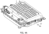
- FIGS. 4A is a perspective view illustrating an example of a battery pack according to one or more embodiments of the present disclosure.
- FIG. 4B is a perspective view illustrating an example of the battery pack of FIG. 4A with a housing element 410 removed.
- the battery pack may include a plurality of battery modules 1000, and a housing 400 for accommodating the plurality of battery modules 1000.
- the housing 400 may include first and second housings 410 and 420 that are connected to (e.g., coupled to or attached to) each other in opposite directions through the plurality of battery modules 1000.
- the plurality of battery modules 1000 may be electrically connected to each other by using a bus bar 430, and the plurality of battery modules 1000 may be electrically connected to each other in a series/parallel method or a series-parallel mixed method, thereby obtaining a desired (e.g., a required) electrical output.
- FIG. 5 is a diagram illustrating a method of charging and discharging the secondary battery according to one or more embodiments of the present disclosure.
- the secondary battery may be charged and discharged by, for example, a CCW charging method.
- the CCCV charging method is a charging method in which a constant current (CC) charging is performed until the voltage reaches a suitable voltage or a reference voltage (e.g., a predetermined voltage), and then a constant voltage (CV) charging is performed until the amount of current flowing decreases, or in more detail, until an end current value is reached.
- a constant current (CC) charging is performed until the voltage reaches a suitable voltage or a reference voltage (e.g., a predetermined voltage)
- CV constant voltage
- a switch of a constant current power supply is turned on, and a switch of a constant voltage power supply is turned off, so that a constant current I flows through the secondary battery.
- a voltage VC applied to a secondary battery capacitor C increases with time. Therefore, a secondary battery voltage VB may rise over time.
- the CC charging is switched to the CV charging.
- a suitable or reference voltage e.g., a predetermined voltage
- the switch of the constant voltage power supply is turned on, and the switch of the constant current power supply is turned off, so that the secondary battery voltage VB is constant.
- the voltage VC applied to the secondary battery capacitor C increases with time.
- the current I flowing through the secondary battery reaches a suitable or reference current (e.g., a predetermined current), for example, such as about 0.01 C
- a suitable or reference current e.g., a predetermined current
- the CCCV charging is finished, all switches are turned off and the current I becomes 0, as shown in FIG. 5-(C) .
- the voltage VR applied to the internal resistor R becomes 0 V. Accordingly, even when a voltage drop is prevented or substantially prevented across the internal resistor R, the secondary battery voltage V B may not substantively decrease.
- FIG. 5-(D) shows a graph of a secondary battery voltage V B and a charging current during the CCCV charging and after the CCCV charging is terminated. Even after the CCCV charging is terminated, the secondary battery voltage VB may not substantively decrease as shown in FIG. 5-(D) .
- FIG. 6 is a graph illustrating a decrease in the negative electrode potential values due to the deterioration of the secondary battery.
- a first example 610 is a graph illustrating a change in a positive electrode potential value 612 and a change in a negative electrode potential value 614 during the charging of the secondary battery in a case where the state of health (SOH) of the secondary battery is 100%.
- the difference between the positive electrode potential value 612 and the negative electrode potential value 614 represents the voltage of the secondary battery cell.
- the positive electrode potential value 612 may increase, and the negative electrode potential value 614 may decrease, resulting in an increase in the voltage value of the secondary battery cell.
- the negative electrode potential value 614 may not drop below 0 V, even when the secondary battery cell is charged to a suitable voltage (e.g., a predetermined voltage), for example, such as 4 V.
- a suitable voltage e.g., a predetermined voltage
- a second example 620 is a graph illustrating a change in a positive electrode potential value 622 and a change in a negative electrode potential value 624 during the charging of the secondary battery in a case where the state of health (SOH) of the secondary battery is 90%.
- the graph shows that the negative electrode potential value 624 decreases due to the deterioration of the secondary battery, and the negative electrode potential value 624 approaches 0 V when the secondary battery cell is charged to a suitable voltage (e.g., a predetermined voltage).
- a third example 630 is a graph illustrating a change in a positive electrode potential value 632 and a change in a negative electrode potential value 634 during the charging of the secondary battery in a case where the state of health (SOH) of the secondary battery is 80%.
- the graph shows that the negative electrode potential value 634 drops below 0 V, even before the secondary battery cell is charged to a suitable voltage (e.g., a predetermined voltage).
- a short circuit can occur, which may lead to thermal runaway or thermal events.
- the negative electrode potential value drops below 0 V
- lithium may precipitate on the surface of the negative electrode instead of the lithium ions penetrating into the active material layer (e.g., graphite). Not only can this reduce the battery capacity, but the precipitated lithium may form dendrites. This can lead to the occurrence of fine and temporary soft shorts.
- the dendrites may grow and eventually cause a hard short. As a result, thermal runaway or thermal events may occur.
- the monitoring of a state of a secondary battery relies only on detecting a voltage of a secondary battery cell, which is the difference between the positive electrode potential value and the negative electrode potential value. Consequently, all of the first to third examples 610, 620, 630 may be perceived as being the same state.
- the secondary battery module may include at least one secondary battery cell that includes the reference electrode.
- the reference electrode may allow for the accurate calculation of not only the voltage of the secondary battery cell, but also the positive electrode potential value and/or the negative electrode potential value. Accordingly, in a case where the negative electrode potential value drops below 0 V, the battery management system may promptly detect an abnormal state. This enables the early detection of not only hard shorts but also soft shorts as well.
- FIG. 7 is a diagram illustrating an example of detecting an abnormal state of a secondary battery according to one or more embodiments of the present disclosure.
- a first example 700 is a graph illustrating a change in a temperature 710 of the secondary battery and a change in a negative electrode potential value 720.
- the abnormal state may be detected by monitoring the voltage of the secondary battery or the temperature 710 of a particular portion of the secondary battery module. For example, in a case where the temperature 710 of a particular or certain portion of the secondary battery module exceeds a threshold temperature, the battery management system of the secondary battery module may detect and issue a warning for the abnormal state. However, in the case of a thermal runaway event, the temperature of the secondary battery module may rise very rapidly. In such cases, the time from when the battery management system detects and issues a warning for the abnormal state (e.g., t1) until an explosion occurs may be very short, and there may not be enough time for users to evacuate safely.
- a warning for the abnormal state e.g., t1
- the secondary battery module may accurately calculate and monitor not only the voltage and the temperature 710 of the secondary battery, but also the negative electrode potential value 720 of the secondary battery as well. Therefore, in a case where the negative electrode potential value 720 falls below a threshold value (e.g., 0 V), the battery management system of the secondary battery module may detect and issue a warning for the abnormal state. In this case, there may be sufficient time for the users to evacuate from the moment the battery management system detects and issues the warning for the abnormal state (e.g., at t2, where t2 ⁇ t1) until the explosion occurs.
- a threshold value e.g., 0 V
Landscapes
- Chemical & Material Sciences (AREA)
- Chemical Kinetics & Catalysis (AREA)
- Electrochemistry (AREA)
- General Chemical & Material Sciences (AREA)
- Engineering & Computer Science (AREA)
- Manufacturing & Machinery (AREA)
- Health & Medical Sciences (AREA)
- Life Sciences & Earth Sciences (AREA)
- Analytical Chemistry (AREA)
- Physics & Mathematics (AREA)
- Molecular Biology (AREA)
- Biochemistry (AREA)
- General Health & Medical Sciences (AREA)
- General Physics & Mathematics (AREA)
- Immunology (AREA)
- Pathology (AREA)
- Microelectronics & Electronic Packaging (AREA)
- Connection Of Batteries Or Terminals (AREA)
- Secondary Cells (AREA)
- Sealing Battery Cases Or Jackets (AREA)
Applications Claiming Priority (1)
| Application Number | Priority Date | Filing Date | Title |
|---|---|---|---|
| KR1020230159425A KR20250072355A (ko) | 2023-11-16 | 2023-11-16 | 이차 전지 및 이차 전지 모듈 |
Publications (2)
| Publication Number | Publication Date |
|---|---|
| EP4557446A2 true EP4557446A2 (de) | 2025-05-21 |
| EP4557446A3 EP4557446A3 (de) | 2025-06-04 |
Family
ID=91899192
Family Applications (1)
| Application Number | Title | Priority Date | Filing Date |
|---|---|---|---|
| EP24187822.2A Pending EP4557446A3 (de) | 2023-11-16 | 2024-07-10 | Wiederaufladbare batterie und wiederaufladbares batteriemodul |
Country Status (3)
| Country | Link |
|---|---|
| US (1) | US20250167410A1 (de) |
| EP (1) | EP4557446A3 (de) |
| KR (1) | KR20250072355A (de) |
Family Cites Families (2)
| Publication number | Priority date | Publication date | Assignee | Title |
|---|---|---|---|---|
| US20210218118A1 (en) * | 2020-01-15 | 2021-07-15 | Apple Inc. | Rechargeable battery with incorporated reference electrode |
| EP3916826A1 (de) * | 2020-05-29 | 2021-12-01 | VARTA Microbattery GmbH | Elektrochemische zelle |
-
2023
- 2023-11-16 KR KR1020230159425A patent/KR20250072355A/ko active Pending
-
2024
- 2024-04-08 US US18/629,711 patent/US20250167410A1/en active Pending
- 2024-07-10 EP EP24187822.2A patent/EP4557446A3/de active Pending
Also Published As
| Publication number | Publication date |
|---|---|
| EP4557446A3 (de) | 2025-06-04 |
| US20250167410A1 (en) | 2025-05-22 |
| KR20250072355A (ko) | 2025-05-23 |
Similar Documents
| Publication | Publication Date | Title |
|---|---|---|
| KR101577387B1 (ko) | 이차전지, 이를 포함하는 이차전지 모듈 및 이차전지 팩 | |
| KR20130089376A (ko) | 온도 센서를 포함하는 이차전지 | |
| EP4621932A1 (de) | Ladesteuerungsverfahren und -vorrichtung für batterie | |
| EP4567389A1 (de) | Sammelschienenhalteranordnung, batteriemodul damit und verfahren zur herstellung davon | |
| EP4560802A1 (de) | Batteriepack | |
| EP4471918A1 (de) | Feuerlöschsystem für batteriepack | |
| EP4557446A2 (de) | Wiederaufladbare batterie und wiederaufladbares batteriemodul | |
| EP4607668A1 (de) | Batteriezellen und batteriemodule | |
| EP4564555A1 (de) | Batteriemodul | |
| US20250286208A1 (en) | Secondary battery and secondary battery module including the same | |
| EP4687192A1 (de) | Batterieverwaltungssystem zur unterstützung mehrerer sekundärbatteriemodule | |
| EP4718573A1 (de) | Batterieverwaltungsvorrichtung zur temperatursteuerung eines energiespeichersystems und verfahren zur temperatursteuerung eines energiespeichersystems | |
| EP4567968A1 (de) | Batteriemodul, seitenabdeckung des batteriemoduls und verfahren zur herstellung der seitenabdeckung des batteriemoduls | |
| EP4697558A1 (de) | Batterieverwaltungssystem mit aufweckfunktion und aufweckverfahren für batterieverwaltungssystem | |
| EP4648182A1 (de) | Batteriemodul | |
| US20260121348A1 (en) | Apparatus for connector fastening and battery control unit | |
| US20250192237A1 (en) | Secondary battery and battery pack including the same | |
| US20260128480A1 (en) | Secondary battery | |
| EP4621895A1 (de) | Verfahren zur herstellung einer sekundärbatterie und damit hergestellte sekundärbatterie | |
| EP4553939A1 (de) | Sekundärbatteriemodul | |
| EP4407781A1 (de) | Stromversorgungsvorrichtung | |
| KR20260013041A (ko) | 데이터 백업 기능을 갖는 이차전지 충전 시스템 및 데이터 백업 방법 | |
| KR20260013040A (ko) | 에너지저장장치, 배터리 임피던스 측정 장치 및 방법 | |
| KR20250125103A (ko) | 두께 측정 장치 및 방법 | |
| CN119890565A (zh) | 电池和模块 |
Legal Events
| Date | Code | Title | Description |
|---|---|---|---|
| PUAI | Public reference made under article 153(3) epc to a published international application that has entered the european phase |
Free format text: ORIGINAL CODE: 0009012 |
|
| STAA | Information on the status of an ep patent application or granted ep patent |
Free format text: STATUS: REQUEST FOR EXAMINATION WAS MADE |
|
| PUAL | Search report despatched |
Free format text: ORIGINAL CODE: 0009013 |
|
| 17P | Request for examination filed |
Effective date: 20240710 |
|
| AK | Designated contracting states |
Kind code of ref document: A2 Designated state(s): AL AT BE BG CH CY CZ DE DK EE ES FI FR GB GR HR HU IE IS IT LI LT LU LV MC ME MK MT NL NO PL PT RO RS SE SI SK SM TR |
|
| AK | Designated contracting states |
Kind code of ref document: A3 Designated state(s): AL AT BE BG CH CY CZ DE DK EE ES FI FR GB GR HR HU IE IS IT LI LT LU LV MC ME MK MT NL NO PL PT RO RS SE SI SK SM TR |
|
| RIC1 | Information provided on ipc code assigned before grant |
Ipc: H01M 10/44 20060101ALI20250429BHEP Ipc: H01M 50/569 20210101ALI20250429BHEP Ipc: H01M 50/553 20210101ALI20250429BHEP Ipc: H01M 50/103 20210101ALI20250429BHEP Ipc: H01M 10/48 20060101ALI20250429BHEP Ipc: H01M 10/42 20060101AFI20250429BHEP |