EP4557455A1 - Batteriemodulanordnung, batteriepack und fahrzeug - Google Patents
Batteriemodulanordnung, batteriepack und fahrzeug Download PDFInfo
- Publication number
- EP4557455A1 EP4557455A1 EP23209780.8A EP23209780A EP4557455A1 EP 4557455 A1 EP4557455 A1 EP 4557455A1 EP 23209780 A EP23209780 A EP 23209780A EP 4557455 A1 EP4557455 A1 EP 4557455A1
- Authority
- EP
- European Patent Office
- Prior art keywords
- battery module
- cylindrical
- holder
- battery
- module arrangement
- Prior art date
- Legal status (The legal status is an assumption and is not a legal conclusion. Google has not performed a legal analysis and makes no representation as to the accuracy of the status listed.)
- Pending
Links
Images


Classifications
-
- H—ELECTRICITY
- H01—ELECTRIC ELEMENTS
- H01M—PROCESSES OR MEANS, e.g. BATTERIES, FOR THE DIRECT CONVERSION OF CHEMICAL ENERGY INTO ELECTRICAL ENERGY
- H01M50/00—Constructional details or processes of manufacture of the non-active parts of electrochemical cells other than fuel cells, e.g. hybrid cells
- H01M50/20—Mountings; Secondary casings or frames; Racks, modules or packs; Suspension devices; Shock absorbers; Transport or carrying devices; Holders
- H01M50/258—Modular batteries; Casings provided with means for assembling
-
- H—ELECTRICITY
- H01—ELECTRIC ELEMENTS
- H01M—PROCESSES OR MEANS, e.g. BATTERIES, FOR THE DIRECT CONVERSION OF CHEMICAL ENERGY INTO ELECTRICAL ENERGY
- H01M10/00—Secondary cells; Manufacture thereof
- H01M10/60—Heating or cooling; Temperature control
- H01M10/61—Types of temperature control
- H01M10/613—Cooling or keeping cold
-
- H—ELECTRICITY
- H01—ELECTRIC ELEMENTS
- H01M—PROCESSES OR MEANS, e.g. BATTERIES, FOR THE DIRECT CONVERSION OF CHEMICAL ENERGY INTO ELECTRICAL ENERGY
- H01M10/00—Secondary cells; Manufacture thereof
- H01M10/60—Heating or cooling; Temperature control
- H01M10/62—Heating or cooling; Temperature control specially adapted for specific applications
- H01M10/625—Vehicles
-
- H—ELECTRICITY
- H01—ELECTRIC ELEMENTS
- H01M—PROCESSES OR MEANS, e.g. BATTERIES, FOR THE DIRECT CONVERSION OF CHEMICAL ENERGY INTO ELECTRICAL ENERGY
- H01M10/00—Secondary cells; Manufacture thereof
- H01M10/60—Heating or cooling; Temperature control
- H01M10/64—Heating or cooling; Temperature control characterised by the shape of the cells
- H01M10/643—Cylindrical cells
-
- H—ELECTRICITY
- H01—ELECTRIC ELEMENTS
- H01M—PROCESSES OR MEANS, e.g. BATTERIES, FOR THE DIRECT CONVERSION OF CHEMICAL ENERGY INTO ELECTRICAL ENERGY
- H01M10/00—Secondary cells; Manufacture thereof
- H01M10/60—Heating or cooling; Temperature control
- H01M10/65—Means for temperature control structurally associated with the cells
- H01M10/655—Solid structures for heat exchange or heat conduction
- H01M10/6556—Solid parts with flow channel passages or pipes for heat exchange
-
- H—ELECTRICITY
- H01—ELECTRIC ELEMENTS
- H01M—PROCESSES OR MEANS, e.g. BATTERIES, FOR THE DIRECT CONVERSION OF CHEMICAL ENERGY INTO ELECTRICAL ENERGY
- H01M10/00—Secondary cells; Manufacture thereof
- H01M10/60—Heating or cooling; Temperature control
- H01M10/65—Means for temperature control structurally associated with the cells
- H01M10/655—Solid structures for heat exchange or heat conduction
- H01M10/6556—Solid parts with flow channel passages or pipes for heat exchange
- H01M10/6557—Solid parts with flow channel passages or pipes for heat exchange arranged between the cells
-
- H—ELECTRICITY
- H01—ELECTRIC ELEMENTS
- H01M—PROCESSES OR MEANS, e.g. BATTERIES, FOR THE DIRECT CONVERSION OF CHEMICAL ENERGY INTO ELECTRICAL ENERGY
- H01M50/00—Constructional details or processes of manufacture of the non-active parts of electrochemical cells other than fuel cells, e.g. hybrid cells
- H01M50/20—Mountings; Secondary casings or frames; Racks, modules or packs; Suspension devices; Shock absorbers; Transport or carrying devices; Holders
- H01M50/204—Racks, modules or packs for multiple batteries or multiple cells
- H01M50/207—Racks, modules or packs for multiple batteries or multiple cells characterised by their shape
- H01M50/213—Racks, modules or packs for multiple batteries or multiple cells characterised by their shape adapted for cells having curved cross-section, e.g. round or elliptic
-
- H—ELECTRICITY
- H01—ELECTRIC ELEMENTS
- H01M—PROCESSES OR MEANS, e.g. BATTERIES, FOR THE DIRECT CONVERSION OF CHEMICAL ENERGY INTO ELECTRICAL ENERGY
- H01M50/00—Constructional details or processes of manufacture of the non-active parts of electrochemical cells other than fuel cells, e.g. hybrid cells
- H01M50/20—Mountings; Secondary casings or frames; Racks, modules or packs; Suspension devices; Shock absorbers; Transport or carrying devices; Holders
- H01M50/244—Secondary casings; Racks; Suspension devices; Carrying devices; Holders characterised by their mounting method
-
- H—ELECTRICITY
- H01—ELECTRIC ELEMENTS
- H01M—PROCESSES OR MEANS, e.g. BATTERIES, FOR THE DIRECT CONVERSION OF CHEMICAL ENERGY INTO ELECTRICAL ENERGY
- H01M50/00—Constructional details or processes of manufacture of the non-active parts of electrochemical cells other than fuel cells, e.g. hybrid cells
- H01M50/20—Mountings; Secondary casings or frames; Racks, modules or packs; Suspension devices; Shock absorbers; Transport or carrying devices; Holders
- H01M50/249—Mountings; Secondary casings or frames; Racks, modules or packs; Suspension devices; Shock absorbers; Transport or carrying devices; Holders specially adapted for aircraft or vehicles, e.g. cars or trains
-
- H—ELECTRICITY
- H01—ELECTRIC ELEMENTS
- H01M—PROCESSES OR MEANS, e.g. BATTERIES, FOR THE DIRECT CONVERSION OF CHEMICAL ENERGY INTO ELECTRICAL ENERGY
- H01M2220/00—Batteries for particular applications
- H01M2220/20—Batteries in motive systems, e.g. vehicle, ship, plane
-
- Y—GENERAL TAGGING OF NEW TECHNOLOGICAL DEVELOPMENTS; GENERAL TAGGING OF CROSS-SECTIONAL TECHNOLOGIES SPANNING OVER SEVERAL SECTIONS OF THE IPC; TECHNICAL SUBJECTS COVERED BY FORMER USPC CROSS-REFERENCE ART COLLECTIONS [XRACs] AND DIGESTS
- Y02—TECHNOLOGIES OR APPLICATIONS FOR MITIGATION OR ADAPTATION AGAINST CLIMATE CHANGE
- Y02E—REDUCTION OF GREENHOUSE GAS [GHG] EMISSIONS, RELATED TO ENERGY GENERATION, TRANSMISSION OR DISTRIBUTION
- Y02E60/00—Enabling technologies; Technologies with a potential or indirect contribution to GHG emissions mitigation
- Y02E60/10—Energy storage using batteries
Definitions
- the disclosure relates generally to energy storage systems.
- the disclosure relates to a battery module arrangement, a battery pack, and to a vehicle.
- the disclosure can be applied to heavy-duty vehicles, such as trucks, buses, and construction equipment, among other vehicle types.
- heavy-duty vehicles such as trucks, buses, and construction equipment, among other vehicle types.
- trucks, buses, and construction equipment among other vehicle types.
- the disclosure may be described with respect to a particular vehicle, the disclosure is not restricted to any particular vehicle.
- a battery pack typically comprises a plurality of battery cells, i.e., electrochemical battery cells, which are electrically connected in series and/or in parallel.
- the battery pack may comprise one or more separate battery modules, wherein each module comprises a stack of battery cells.
- the battery cells may be cylindrical battery cells.
- a battery module arrangement for a battery pack has a longitudinal extension in a longitudinal direction, a width extension in a width direction and a height extension in a height direction.
- the battery module arrangement comprises:
- the height direction typically corresponds to a vertical direction when the battery module arrangement is used. Accordingly, the height direction may be defined as a normal to a substantially horizontally extending plane.
- the longitudinal direction, the width direction and the height direction are perpendicular to each other.
- the longitudinal extension of each cylindrical battery cell extends along a center axis of the cylindrical battery cell.
- the battery module arrangement comprises a bottom bracket provided below the first and second holders, as seen in the height direction, wherein the bottom bracket connects the first and second holders and is configured as a load-bearing support structure for the first and second holders.
- loads can be transferred at two offset locations, i.e., between the first holder and the bottom bracket, and also between the second holder and the bottom bracket.
- a more robust and rigid configuration may be achieved, e.g., reducing the risk of unwanted vibrations when the battery module arrangement is used on a moving object, such as on a vehicle.
- the second holder comprises:
- the cooling plate member is further located adjacent the fourth side of the second holder and extends in the width direction and the height direction such that the cooling plate member faces each one of end portions of the second set of cylindrical battery cells.
- a technical benefit may include that cooling of the first and second sets of cylindrical battery cells is achieved in a space efficient manner.
- the cooling plate member comprises an inlet and an outlet for coolant fluid, wherein the inlet and/or the outlet are/is provided at a side of the battery module arrangement which is facing away from the battery module arrangement in a direction which is substantially perpendicular to the longitudinal direction.
- a technical benefit may include that a more favorable location for the respective cooling inlet/outlet is achieved, resulting in e.g., a more space efficient configuration.
- a battery pack comprising at least one battery module arrangement according to any one of the examples of the first aspect of the disclosure.
- the second aspect of the disclosure may seek to provide an improved battery pack which is reliable, robust and space efficient.
- a technical benefit may include that an efficient packaging in the longitudinal direction may be achieved.
- Further technical benefits may include that the configuration allows for increased design freedom, it may facilitate installation of cooling features for the cylindrical battery cells, and/or it may result in a rigid configuration which reduces the risk of vibrations.
- the battery pack comprises a housing, and the at least one battery module arrangement is provided in the housing.
- a technical benefit may include that the at least one battery module arrangement is protected by the housing.
- the battery pack comprises at least two battery module arrangements according to any one of the examples of the first aspect of the disclosure, wherein the battery module arrangements are stacked next to each other along a longitudinal direction of the battery pack which corresponds to the longitudinal directions of the at least two battery module arrangements.
- a technical benefit may include that a space efficient packaging is achieved.
- the battery pack comprises at least one connecting bracket which connects, i.e., mechanically connects, the at least two battery module arrangements.
- a technical benefit may include that improved structural support is provided, resulting in a more robust and rigid battery pack.
- the at least one connecting bracket connects the at least two battery module arrangements via respective sides of the battery module arrangements which are facing away from the battery module arrangements in a direction which is substantially perpendicular to the longitudinal direction of the battery pack.
- a technical benefit may include that a space efficient and robust battery pack is achieved, where there e.g., is no need for further connecting brackets on other sides of the battery module arrangements which are perpendicular to the first and second directions.
- the at least one connecting bracket is further connected to the housing, such as by at least one weld and/or by a fastening member, such as a screw, rivet or bolt.
- the battery pack comprises a plurality of connecting brackets which extend in the longitudinal direction of the battery pack and which are arranged on top of each other in a height direction of the battery pack, which corresponds to the height directions of the at least two battery module arrangements.
- a technical benefit may include that a more robust and rigid battery pack is achieved.
- the at least one connecting bracket connects the at least two battery module arrangements by at least one of a weld and a fastening member, such as a screw, rivet or bolt.
- a vehicle comprising a battery module arrangement according to any one of the examples of the first aspect of the disclosure and/or a battery pack according to any one of the examples of the second aspect of the disclosure is provided.
- Advantages and effects of the third aspect of the disclosure are analogous to the advantages and effects of the first and second aspects of the disclosure.
- An aim of the present disclosure is to provide an improved battery module arrangement, a battery pack, and/or a vehicle, which alleviate one or more drawbacks of the prior art, or which at least provide suitable alternatives.
- an aim of the present disclosure is to provide a battery module arrangement and/or a battery pack which is/are reliable, robust, space efficient, and/or cost effective.
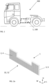
- Fig. 1 is an exemplary vehicle 200 in a side view according to an example.
- the vehicle 200 is in this example a truck, and more particularly a towing truck for towing one or more trailers (not shown). It shall however be noted that the vehicle may be any other type of vehicle, such as another type of truck, a bus, a passenger car, a marine vessel, or construction equipment, such as a wheel loader or an excavator.
- the vehicle 200 comprises a battery module arrangement 1 and a battery pack 100 according to an example disclosed herein.
- the battery pack 100 may at least partly be used for driving one or more electric motors (not shown) of the vehicle 200.
- the vehicle 200 may accordingly be an electric vehicle or a hybrid vehicle, i.e., a vehicle which at least partly uses electric power for propulsion.
- the battery module arrangement 1 and the battery pack 100 as disclosed herein may also be used in a stationary unit, such as a building and/or any stationary machinery.
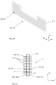
- FIG. 2a is an exemplary battery module arrangement 1 in a perspective view according to an example.
- the battery module arrangement 1 has a longitudinal extension in a longitudinal direction L, a width extension in a width direction W and a height extension in a height direction H.
- the height direction H may correspond to a vertical direction when the battery module arrangement 1 is provided on a flat horizontally extending surface.
- the directions L, W and H are perpendicular to each other.
- the battery module arrangement 1 comprises a first set of cylindrical battery cells 2 and a first holder 3 for the first set of cylindrical battery cells 2.
- the cylindrical battery cells 2 may be any type of electrochemical battery cells, such as lithium-ion cells.
- the cylindrical battery cells 2 may be electrically connected in series and/or at least partly in parallel.
- FIG. 2c shows a sectional view of a battery module arrangement 1 according to an example.
- the battery module arrangement 1 in FIG. 2c may be the battery module arrangement 1 as shown in FIG. 2a .
- the sectional view is defined by a geometrical plane extending in the longitudinal direction L and the height direction H of the battery module arrangement 1.
- the first holder 3 has a first side 31 facing in a first direction which corresponds to the longitudinal direction L and a second side 32 facing in a second direction being opposite to the first direction.
- the first holder 3 comprises a plurality of cylindrical apertures 33 and each cylindrical aperture 33 extends through the first holder 3 along the longitudinal direction L between the first and second sides 31, 32.
- Each cylindrical battery cell 2 of the first set of cylindrical battery cells 2 is provided in a respective cylindrical aperture 33 of the plurality of cylindrical apertures 33 such that the cylindrical battery cell 2 has a longitudinal extension along the longitudinal direction L. More specifically, a respective center axis C1 of each cylindrical battery cell 2 extends along the longitudinal direction L.
- each battery cell 2 may extend along a horizontal direction when the battery module arrangement 1 is provided on a flat horizontally extending surface.
- Each cylindrical battery cell 2 of the first set of cylindrical battery cells 2 is provided in the respective cylindrical aperture 33 such that the cylindrical battery cell 2 protrudes from the first holder 3 on the first side 31 and on the second side 32.
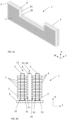
- FIG. 3a is an exemplary battery module arrangement 1 in perspective view according to an example.
- the battery module arrangement 1 may comprise the first set of battery cells 2 and the first holder 3 as e.g., shown in FIGS. 2a-c .
- the battery module arrangement 1 may further comprise a second set of cylindrical battery cells 4 and a second holder 5 for the second set of cylindrical battery cells 4.
- the second set of cylindrical battery cells 4 and the second holder 5 may be configured as the first set of cylindrical battery cells 2 and the first holder 3, respectively. Accordingly, the example shown in FIGS. 2a-c may also depict the second set of cylindrical battery cells 4 and the second holder 5.
- Each cylindrical battery cell 4 of the second set of cylindrical battery cells 4 is provided in a respective cylindrical aperture 53 of the plurality of cylindrical apertures 53 such that the cylindrical battery cell 4 has a longitudinal extension along the longitudinal direction L, and each cylindrical battery cell 4 of the second set of cylindrical battery cells 4 is provided in the respective cylindrical aperture 53 such that the cylindrical battery cell 4 protrudes from the second holder 5 on the third side 51 and on the fourth side 52.
- the center axis C1 of each battery cell 4 may extend along a horizontal direction when the battery module arrangement 1 is provided on a flat horizontally extending surface.
- FIG. 3b shows a sectional view of a battery module arrangement 1 according to an example.
- the battery module arrangement 1 may be the battery module arrangement 1 shown in FIG. 3a .
- the sectional view is also here defined by a geometrical plane extending in the longitudinal direction L and the height direction H of the battery module arrangement 1.
- FIG. 3c shows a battery module arrangement 1 in a perspective view according to an example.
- the battery module arrangement 1 may as shown comprise a bottom bracket 6 provided below the first and second holders 3, 5, as seen in the height direction H.
- the bottom bracket 6 connects, i.e., mechanically connects, the first and second holders 3, 5 and is configured as a load-bearing support structure for the first and second holders 3, 5.
- the bottom bracket 6 may be a plate member, such as made of a fiber reinforced polymer or a metallic material, e.g., aluminum.
- the battery module arrangement 1 may as shown in FIG. 3c further comprise at least one side bracket 71, 72 provided on a side of the first and second holders 3, 5 which faces away from the battery module arrangement 1 in a direction along the width direction W, wherein the at least one side bracket 71, 72 connects the first and second holders 3, 5, i.e., mechanically connects the first and second holders 3, 5.
- the battery module arrangement 1 comprises a first side bracket 71 and a second side bracket 72, provided on opposite sides of the battery module arrangement 1.
- the at least one side bracket 71, 72 may be a plate member, such as made of a fiber reinforced polymer or a metallic material, e.g., aluminum.
- an at least partly enclosed battery module arrangement 1 may be provided. This may result in a more robust and rigid arrangement.
- the first holder 3 may as shown comprise a first wall member 311 associated with the first side 31 and a second wall member 321 associated with the second side 32.
- the first and second wall members 311, 321 are offset from each other in the longitudinal direction L such that a space S is formed therebetween.
- the first holder 3 may be an at least partly hollow member, thereby saving weight.
- the second holder 5 may additionally or alternatively comprise a third wall member 511 associated with the third side 51 and a fourth wall member 521 associated with the fourth side 52.
- the third and fourth wall members 511, 521 are offset from each other in the longitudinal direction L such that a space S is formed therebetween.
- the wall members may form the respective sides of the holders 3, 5.
- the battery module arrangement 1 may as shown comprise a cooling plate member 8 for cooling the cylindrical battery cells 2, 4.
- the cooling plate member 8 is located adjacent the first side 31 of the first holder 3 and extends in the width direction W and the height direction H such that the cooling plate member 8 faces each one of end portions 21 of the first set of cylindrical battery cells 2.
- the cooling plate member 8 may further as shown be located adjacent the fourth side 52 of the second holder 5 and extend in the width direction W and the height direction H such that the cooling plate member 8 faces each one of end portions 41 of the second set of cylindrical battery cells 4. Accordingly, the cooling plate member 8 may as shown be located in-between the first and second holders 3, 5, for cooling the cylindrical battery cells 2, 4.
- the cooling plate member 8 may comprise a cooling circuit (not shown) for coolant.
- the cooling plate member may comprise an inlet 81 and an outlet 82 for coolant fluid, wherein the inlet 81 and/or the outlet 82 are/is provided at a side 11 of the battery module arrangement 1 which is facing away from the battery module arrangement 1 in a direction which is substantially perpendicular to the longitudinal direction L.
- the side 11 is a top side of the battery module arrangement 1.
- the inlet 81 and/or the outlet 82 may be provided on a side of the battery module arrangement 1 which faces in a direction along the width direction W.
- the battery module arrangement 1 has a U-shaped profile, wherein the inlet 81 and/or the outlet 82 are provided on an inner side of the U-shaped profile which faces in a direction along the width direction W.
- FIG. 4 depicts another exemplary battery module arrangement 1 according to an example.
- the battery module arrangement 1 comprises a bottom bracket 6 provided below the first holder 3, as seen in the height direction H. It also comprises a cooling plate member 8 according to examples disclosed herein.
- the cooling plate member 8 is connected, i.e., mechanically connected, to the first holder 3 and to the bottom bracket 6 such that loads can be transferred via the cooling plate member 8 between the first holder 3 and the bottom bracket 6.
- a robust and rigid arrangement may be provided without the use of a second holder as disclosed herein.
- FIG 5a and FIG. 5b show exemplary battery packs 100 in perspective views according to examples.
- the battery pack 100 comprises at least one battery module arrangement 1 as disclosed herein.
- the battery pack 1 comprises four battery module arrangements 1 stacked next to each other along the longitudinal direction L of the battery pack 100, which corresponds to the longitudinal direction L of the battery module arrangements 1. Accordingly, any number of battery module arrangement(s) 1 may be stacked next to each other in the longitudinal direction L of the battery pack 100, corresponding to the longitudinal direction L of the battery module arrangement(s) 1.
- the directions L, W and H for the battery pack 100 may thus be the same as for the battery module arrangement 1 disclosed herein.
- the battery pack 100 may as further shown comprise a housing 110, wherein the at least one battery module arrangement 1 is provided in the housing 110.
- Each battery module arrangement 1 may be configured as a separate cassette which is provided inside the housing 110.
- each battery module arrangement 1 may be insertable and removable from the housing 110 from above, as seen in the height direction H. Additionally, or alternatively, each battery module arrangement 1 may be insertable and removable from the housing 110 from an outer side facing in a direction along the width direction W.
- the battery pack has a U-shaped profile, as seen in a geometrical plane extending in the width direction W and the height direction H.
- beam members (not shown) of a vehicle chassis may extend at least partly inside the U-shaped profile along the longitudinal direction L.
- the beam members of the vehicle chassis may extend in a longitudinal direction of the vehicle, corresponding to a travel direction of the vehicle.
- the U-shaped profile may result in improved packaging of the cylindrical battery cells 2, 4 inside a vehicle.
- the battery pack may have an L-shaped profile or an H-shaped profile.
- the battery pack 100 may comprise at least one connecting bracket 120 which connects, i.e., mechanically connects, at least two of the battery module arrangements 1.
- the at least one connecting bracket 120 connects all of the battery module arrangements 1.
- connecting brackets 120 there are four connecting brackets 120. However, it shall be noted that there may be more or fewer connecting brackets.
- the at least one connecting bracket 120 may be connected to the housing 110, such as by at least one weld 111 and/or by a fastening member, such as a screw, rivet or bolt.
- the connecting brackets 120 may as shown extend in the longitudinal direction L of the battery pack 100 and be arranged on top of each other in the height direction H of the battery pack which corresponds to the height directions H of the at least two battery module arrangements 1.
- the at least one connecting bracket 120 may connect the at least two battery module arrangements 1 by at least one of a weld and a fastening member, such as a screw, rivet or bolt.
- Example 2 The battery module arrangement (1) according to example 1, comprising:
- Example 3 The battery module arrangement (1) according to example 2, comprising a bottom bracket (6) provided below the first and second holders (3, 5), as seen in the height direction (H), wherein the bottom bracket (6) connects the first and second holders (3, 5) and is configured as a load-bearing support structure for the first and second holders (3, 5).
- Example 4 The battery module arrangement (1) according to any one of examples 2-3, comprising at least one side bracket (71, 72) provided on a side of the first and second holders (3, 5) which faces away from the battery module arrangement (1) in a direction along the width direction (W), wherein the at least one side bracket (71, 72) connects the first and second holders (3, 5).
- Example 5 The battery module arrangement (1) according to any one of examples 3-4, wherein the bottom bracket (6) and/or the at least side bracket (71, 72) according to claim 4 connects the first and second holders (3, 5) by at least one of a weld and a fastening member, such as a screw, rivet or bolt.
- a fastening member such as a screw, rivet or bolt.
- Example 6 The battery module arrangement (1) according to any one of the preceding examples, wherein the first holder (3) comprises:
- Example 7 The battery module arrangement (1) according to any one of the preceding examples, when also being dependent on example 2, wherein the second holder (5) comprises:
- Example 8 The battery module arrangement (1) according to any one of the preceding examples, further comprising a cooling plate member (8) for cooling the cylindrical battery cells (2, 4), wherein the cooling plate member (8) is located adjacent the first side (31) of the first holder (3) and extends in the width direction (W) and the height direction (H) such that the cooling plate member (8) faces each one of end portions (21) of the first set of cylindrical battery cells (2).
- Example 9 The battery module arrangement (1) according to example 8, when also being dependent on example 2, wherein the cooling plate member (8) is further located adjacent the fourth side of the second holder (5) and extends in the width direction (W) and the height direction (H) such that the cooling plate member (8) faces each one of end portions (41) of the second set of cylindrical battery cells (4).
- Example 10 The battery module arrangement (1) according to example 8 or 9, wherein the cooling plate member (8) comprises an inlet (81) and an outlet (82) for coolant fluid, wherein the inlet (81) and/or the outlet (82) are/is provided at a side (11) of the battery module arrangement (1) which is facing away from the battery module arrangement (1) in a direction which is substantially perpendicular to the longitudinal direction (L).
- the cooling plate member (8) comprises an inlet (81) and an outlet (82) for coolant fluid, wherein the inlet (81) and/or the outlet (82) are/is provided at a side (11) of the battery module arrangement (1) which is facing away from the battery module arrangement (1) in a direction which is substantially perpendicular to the longitudinal direction (L).
- Example 11 The battery module arrangement (1) according to any one of examples 8-10, comprising a bottom bracket (6) provided below the first holder (3), as seen in the height direction (H), wherein the cooling plate member (8) is connected to the first holder (3) and to the bottom bracket (6) such that loads can be transferred via the cooling plate member (8) between the first holder (3) and the bottom bracket (6).
- Example 12 A battery pack (100) comprising at least one battery module arrangement (1) according to any one of the preceding examples.
- Example 13 The battery pack (100) according to example 12, comprising a housing (110), wherein the at least one battery module arrangement (1) is provided in the housing (110).
- Example 14 The battery pack (100) according to any one of examples 12-13, comprising at least two battery module arrangements (1) according to any one of examples 1-11, wherein the battery module arrangements (1) are stacked next to each other along a longitudinal direction (L) of the battery pack (100) which corresponds to the longitudinal directions (L) of the at least two battery module arrangements (1).
- Example 15 The battery pack (100) according to example 14, further comprising at least one connecting bracket (120) which connects the at least two battery module arrangements (1).
- Example 16 The battery pack (100) according to example 15, wherein the at least one connecting bracket (120) connects the at least two battery module arrangements (1) via respective sides (12) of the battery module arrangements (1) which are facing away from the battery module arrangements (1) in a direction which is substantially perpendicular to the longitudinal direction (L) of the battery pack (100).
- Example 17 The battery pack (100) according to example 15 or 16, when also being dependent on example 13, wherein the at least one connecting bracket (120) is further connected to the housing (110), such as by at least one weld (111) and/or by a fastening member, such as a screw, rivet or bolt.
- a fastening member such as a screw, rivet or bolt.
- Example 18 The battery pack (100) according to any one of examples 15-17, comprising a plurality of connecting brackets (120) which extend in the longitudinal direction (L) of the battery pack (100) and which are arranged on top of each other in a height direction (H) of the battery pack which corresponds to the height directions (H) of the at least two battery module arrangements (1).
- Example 19 The battery pack (100) according to any one of examples 15-18, wherein the at least one connecting bracket (120) connects the at least two battery module arrangements (1) by at least one of a weld and a fastening member (), such as a screw, rivet or bolt.
- a fastening member such as a screw, rivet or bolt.
- Example 20 A vehicle (200) comprising a battery module arrangement (1) according to any one of examples 1-11 and/or a battery pack (100) according to any one of examples 12-19.
- Relative terms such as “below” or “above” or “upper” or “lower” or “horizontal” or “vertical” may be used herein to describe a relationship of one element to another element as illustrated in the Figures. It will be understood that these terms and those discussed above are intended to encompass different orientations of the device in addition to the orientation depicted in the Figures. It will be understood that when an element is referred to as being “connected” or “coupled” to another element, it can be directly connected or coupled to the other element, or intervening elements may be present. In contrast, when an element is referred to as being “directly connected” or “directly coupled” to another element, there are no intervening elements present.
Landscapes
- Chemical & Material Sciences (AREA)
- Chemical Kinetics & Catalysis (AREA)
- Electrochemistry (AREA)
- General Chemical & Material Sciences (AREA)
- Engineering & Computer Science (AREA)
- Manufacturing & Machinery (AREA)
- Aviation & Aerospace Engineering (AREA)
- Battery Mounting, Suspending (AREA)
Priority Applications (2)
| Application Number | Priority Date | Filing Date | Title |
|---|---|---|---|
| EP23209780.8A EP4557455A1 (de) | 2023-11-14 | 2023-11-14 | Batteriemodulanordnung, batteriepack und fahrzeug |
| US18/945,925 US20250158202A1 (en) | 2023-11-14 | 2024-11-13 | Battery module arrangement, a battery pack, and a vehicle |
Applications Claiming Priority (1)
| Application Number | Priority Date | Filing Date | Title |
|---|---|---|---|
| EP23209780.8A EP4557455A1 (de) | 2023-11-14 | 2023-11-14 | Batteriemodulanordnung, batteriepack und fahrzeug |
Publications (1)
| Publication Number | Publication Date |
|---|---|
| EP4557455A1 true EP4557455A1 (de) | 2025-05-21 |
Family
ID=88833943
Family Applications (1)
| Application Number | Title | Priority Date | Filing Date |
|---|---|---|---|
| EP23209780.8A Pending EP4557455A1 (de) | 2023-11-14 | 2023-11-14 | Batteriemodulanordnung, batteriepack und fahrzeug |
Country Status (2)
| Country | Link |
|---|---|
| US (1) | US20250158202A1 (de) |
| EP (1) | EP4557455A1 (de) |
Citations (3)
| Publication number | Priority date | Publication date | Assignee | Title |
|---|---|---|---|---|
| EP2650946A1 (de) * | 2012-04-13 | 2013-10-16 | Hitachi Vehicle Energy, Ltd. | Batterieblock und Sekundärbatteriemodul |
| US20170288286A1 (en) * | 2016-04-01 | 2017-10-05 | Faraday&Future Inc. | Liquid temperature regulated battery pack for electric vehicles |
| US20220013840A1 (en) * | 2018-11-02 | 2022-01-13 | Tvs Motor Company Limited | Holder structure for energy storage cells in an energy storage device |
-
2023
- 2023-11-14 EP EP23209780.8A patent/EP4557455A1/de active Pending
-
2024
- 2024-11-13 US US18/945,925 patent/US20250158202A1/en active Pending
Patent Citations (3)
| Publication number | Priority date | Publication date | Assignee | Title |
|---|---|---|---|---|
| EP2650946A1 (de) * | 2012-04-13 | 2013-10-16 | Hitachi Vehicle Energy, Ltd. | Batterieblock und Sekundärbatteriemodul |
| US20170288286A1 (en) * | 2016-04-01 | 2017-10-05 | Faraday&Future Inc. | Liquid temperature regulated battery pack for electric vehicles |
| US20220013840A1 (en) * | 2018-11-02 | 2022-01-13 | Tvs Motor Company Limited | Holder structure for energy storage cells in an energy storage device |
Also Published As
| Publication number | Publication date |
|---|---|
| US20250158202A1 (en) | 2025-05-15 |
Similar Documents
| Publication | Publication Date | Title |
|---|---|---|
| US10486516B2 (en) | Battery mounting structure | |
| US11780336B2 (en) | Battery assembly | |
| EP2072308B1 (de) | Elektrisches Fahrzeug | |
| EP3981628A1 (de) | Fahrzeug | |
| US12555859B2 (en) | Battery mounting structure for vehicle | |
| US20230072733A1 (en) | Battery module and battery pack including battery modules | |
| US20250192309A1 (en) | Interlocking cell stack end plates for multi-tiered traction battery packs | |
| US20240010080A1 (en) | Fuel cell vehicle | |
| US20200127254A1 (en) | Power storage unit and power storage device | |
| EP4557455A1 (de) | Batteriemodulanordnung, batteriepack und fahrzeug | |
| US20250210750A1 (en) | Battery module, a battery pack, and a vehicle | |
| US20250210782A1 (en) | Battery module, a battery pack, and a vehicle | |
| EP4723328A1 (de) | Batteriemodulanordnung, batteriepack und fahrzeug | |
| EP4718596A1 (de) | Batteriepack, fahrzeug und verfahren zur montage eines batteriepacks | |
| EP4571938A1 (de) | Batteriemodul, batteriepack und fahrzeug | |
| US20260128440A1 (en) | Battery pack and a vehicle | |
| EP4738564A1 (de) | Batteriepack und fahrzeug | |
| EP4614636A1 (de) | Batteriepack, fahrzeug und verfahren zur herstellung eines batteriepacks | |
| EP4738539A1 (de) | Batteriepack und fahrzeug | |
| US20260128411A1 (en) | Battery pack and a vehicle | |
| EP4653215A1 (de) | Batteriepackmontageanordnung, batteriepackanordnung, fahrzeug und verfahren | |
| EP4664603A1 (de) | Batteriezellenstapelanordnung, batteriepack, batteriemodul, fahrzeug und verfahren | |
| EP4645543A1 (de) | Batteriepack, fahrzeug und verfahren zur herstellung eines batteriepacks | |
| EP4376168A1 (de) | Batteriestapel mit batteriemodulen und kühlsystem | |
| EP4557475A1 (de) | Batteriemodulpaar |
Legal Events
| Date | Code | Title | Description |
|---|---|---|---|
| PUAI | Public reference made under article 153(3) epc to a published international application that has entered the european phase |
Free format text: ORIGINAL CODE: 0009012 |
|
| STAA | Information on the status of an ep patent application or granted ep patent |
Free format text: STATUS: THE APPLICATION HAS BEEN PUBLISHED |
|
| AK | Designated contracting states |
Kind code of ref document: A1 Designated state(s): AL AT BE BG CH CY CZ DE DK EE ES FI FR GB GR HR HU IE IS IT LI LT LU LV MC ME MK MT NL NO PL PT RO RS SE SI SK SM TR |
|
| STAA | Information on the status of an ep patent application or granted ep patent |
Free format text: STATUS: REQUEST FOR EXAMINATION WAS MADE |
|
| 17P | Request for examination filed |
Effective date: 20251017 |