EP4557510A1 - Dispositif électronique pliable - Google Patents
Dispositif électronique pliable Download PDFInfo
- Publication number
- EP4557510A1 EP4557510A1 EP23917229.9A EP23917229A EP4557510A1 EP 4557510 A1 EP4557510 A1 EP 4557510A1 EP 23917229 A EP23917229 A EP 23917229A EP 4557510 A1 EP4557510 A1 EP 4557510A1
- Authority
- EP
- European Patent Office
- Prior art keywords
- radiator
- electronic device
- location
- foldable electronic
- antenna
- Prior art date
- Legal status (The legal status is an assumption and is not a legal conclusion. Google has not performed a legal analysis and makes no representation as to the accuracy of the status listed.)
- Pending
Links
Images


Classifications
-
- H—ELECTRICITY
- H01—ELECTRIC ELEMENTS
- H01Q—ANTENNAS, i.e. RADIO AERIALS
- H01Q1/00—Details of, or arrangements associated with, antennas
- H01Q1/36—Structural form of radiating elements, e.g. cone, spiral, umbrella; Particular materials used therewith
-
- H—ELECTRICITY
- H01—ELECTRIC ELEMENTS
- H01Q—ANTENNAS, i.e. RADIO AERIALS
- H01Q1/00—Details of, or arrangements associated with, antennas
- H01Q1/12—Supports; Mounting means
- H01Q1/22—Supports; Mounting means by structural association with other equipment or articles
-
- H—ELECTRICITY
- H01—ELECTRIC ELEMENTS
- H01Q—ANTENNAS, i.e. RADIO AERIALS
- H01Q1/00—Details of, or arrangements associated with, antennas
- H01Q1/12—Supports; Mounting means
- H01Q1/22—Supports; Mounting means by structural association with other equipment or articles
- H01Q1/2258—Supports; Mounting means by structural association with other equipment or articles used with computer equipment
- H01Q1/2266—Supports; Mounting means by structural association with other equipment or articles used with computer equipment disposed inside the computer
-
- H—ELECTRICITY
- H01—ELECTRIC ELEMENTS
- H01Q—ANTENNAS, i.e. RADIO AERIALS
- H01Q1/00—Details of, or arrangements associated with, antennas
- H01Q1/12—Supports; Mounting means
- H01Q1/22—Supports; Mounting means by structural association with other equipment or articles
- H01Q1/24—Supports; Mounting means by structural association with other equipment or articles with receiving set
- H01Q1/241—Supports; Mounting means by structural association with other equipment or articles with receiving set used in mobile communications, e.g. GSM
- H01Q1/242—Supports; Mounting means by structural association with other equipment or articles with receiving set used in mobile communications, e.g. GSM specially adapted for hand-held use
- H01Q1/243—Supports; Mounting means by structural association with other equipment or articles with receiving set used in mobile communications, e.g. GSM specially adapted for hand-held use with built-in antennas
-
- H—ELECTRICITY
- H01—ELECTRIC ELEMENTS
- H01Q—ANTENNAS, i.e. RADIO AERIALS
- H01Q1/00—Details of, or arrangements associated with, antennas
- H01Q1/36—Structural form of radiating elements, e.g. cone, spiral, umbrella; Particular materials used therewith
- H01Q1/38—Structural form of radiating elements, e.g. cone, spiral, umbrella; Particular materials used therewith formed by a conductive layer on an insulating support
-
- H—ELECTRICITY
- H01—ELECTRIC ELEMENTS
- H01Q—ANTENNAS, i.e. RADIO AERIALS
- H01Q1/00—Details of, or arrangements associated with, antennas
- H01Q1/50—Structural association of antennas with earthing switches, lead-in devices or lightning protectors
-
- H—ELECTRICITY
- H01—ELECTRIC ELEMENTS
- H01Q—ANTENNAS, i.e. RADIO AERIALS
- H01Q21/00—Antenna arrays or systems
- H01Q21/28—Combinations of substantially independent non-interacting antenna units or systems
-
- H—ELECTRICITY
- H01—ELECTRIC ELEMENTS
- H01Q—ANTENNAS, i.e. RADIO AERIALS
- H01Q5/00—Arrangements for simultaneous operation of antennas on two or more different wavebands, e.g. dual-band or multi-band arrangements
- H01Q5/30—Arrangements for providing operation on different wavebands
- H01Q5/307—Individual or coupled radiating elements, each element being fed in an unspecified way
- H01Q5/314—Individual or coupled radiating elements, each element being fed in an unspecified way using frequency dependent circuits or components, e.g. trap circuits or capacitors
- H01Q5/328—Individual or coupled radiating elements, each element being fed in an unspecified way using frequency dependent circuits or components, e.g. trap circuits or capacitors between a radiating element and ground
-
- H—ELECTRICITY
- H01—ELECTRIC ELEMENTS
- H01Q—ANTENNAS, i.e. RADIO AERIALS
- H01Q9/00—Electrically-short antennas having dimensions not more than twice the operating wavelength and consisting of conductive active radiating elements
- H01Q9/04—Resonant antennas
- H01Q9/30—Resonant antennas with feed to end of elongated active element, e.g. unipole
- H01Q9/42—Resonant antennas with feed to end of elongated active element, e.g. unipole with folded element, the folded parts being spaced apart a small fraction of the operating wavelength
-
- H—ELECTRICITY
- H04—ELECTRIC COMMUNICATION TECHNIQUE
- H04M—TELEPHONIC COMMUNICATION
- H04M1/00—Substation equipment, e.g. for use by subscribers
- H04M1/02—Constructional features of telephone sets
- H04M1/0202—Portable telephone sets, e.g. cordless phones, mobile phones or bar type handsets
- H04M1/0206—Portable telephones comprising a plurality of mechanically joined movable body parts, e.g. hinged housings
- H04M1/0208—Portable telephones comprising a plurality of mechanically joined movable body parts, e.g. hinged housings characterized by the relative motions of the body parts
- H04M1/0214—Foldable telephones, i.e. with body parts pivoting to an open position around an axis parallel to the plane they define in closed position
- H04M1/0216—Foldable in one direction, i.e. using a one degree of freedom hinge
Definitions
- Embodiments of this application relate to the field of electronic devices, and more specifically, to a foldable electronic device.
- a foldable electronic device may switch between a folded state and an unfolded state.
- space occupied by the foldable electronic device is small.
- the foldable electronic device may display a large screen, to increase a view range available for a user.
- the foldable electronic device has become a general development orientation of current technologies.
- Embodiments of this application provide a foldable electronic device, to improve antenna performance of the foldable electronic device in a folded state.
- a foldable electronic device including: a first housing and a second housing, where the first housing includes a first side frame, and the second housing includes a second side frame; a hinge, where the hinge is located between the first housing and the second housing, and the hinge is rotatably connected to the first housing and the second housing separately; and an antenna, where the antenna includes a first radiator and a second radiator, the first radiator includes a part of the first side frame, and the second radiator includes a part of the second side frame, where a feed point is disposed on the first radiator, and is configured to feed the antenna, and a length of the second radiator is greater than a length of the first radiator; and when the foldable electronic device is in a folded state, in a thickness direction of the foldable device, the first radiator and the second radiator are disposed opposite to each other at a first spacing, and at least a part of the first radiator overlaps the second radiator, so that the first radiator is coupled to the second radiator.
- radio frequency energy of the first radiator can be transferred to the second radiator through coupling, to excite the second radiator to generate radiation, so that the second radiator serves as the parasitic stub and operates together with the first radiator.
- the length of the second radiator is set to be greater than the length of the first radiator. This helps further improve a radiation capability of the second radiator, to improve a radiation capability of the radio frequency energy transferred by the first radiator to the second radiator through coupling. In this way, radiation efficiency of the first radiator can be improved, and an operating bandwidth of the antenna can be extended. This helps reduce adverse impact on antenna performance caused by a reduced ground plane size or overlapping coverage of the housings in a folded state, to improve the antenna performance of the foldable electronic device in a folded state, so that the foldable electronic device has a good radiation characteristic.
- the length L1 of the first radiator and the length L2 of the second radiator satisfy: L2 ⁇ 1.5L1.
- the radiation efficiency of the first radiator is improved by increasing the length of the second radiator.
- the radiation efficiency of the first radiator may be improved by about 1 dB.
- the first radiator includes a first end and a second end, the first end is grounded, and the feed point is at a location that is on the first radiator and that is close to the second end; and the second radiator includes a third end and a fourth end, and the third end is grounded.
- an electrical length of the second radiator may be a quarter of an operating wavelength of the second radiator, that is, the second radiator is a quarter-wave antenna.
- the foldable electronic device further includes a switching circuit, a connection point is disposed on the second radiator, and the connection point is at a location that is on the second radiator and that is close to the fourth end; and one end of the switching circuit is grounded, and another end of the switching circuit is connected to the connection point, to adjust a resonance frequency of the second radiator.
- the switching circuit is disposed, so that the resonance frequency of the second radiator serving as the parasitic stub can be adjusted.
- the antenna can cover different frequency bands. This helps meet a communication requirement.
- a distance D1 between the connection point and the fourth end satisfies: 1/3L2 ⁇ D1 ⁇ 1/2L2, where L2 is the length of the second radiator, so that a coupling requirement of the first radiator and the second radiator can be better met.
- the switching circuit includes a switch component and a plurality of matching branches in parallel with the device, one end of the switch component is grounded, another end of the switch component is connected to the plurality of matching branches, and other ends of the plurality of matching branches are connected to the connection point; and the switch component switches between the plurality of matching branches, to adjust the resonance frequency of the second radiator.
- the first side frame has a first location and a second location, and the second side frame has a third location and a fourth location;
- the first radiator includes the first side frame between the first location and the second location;
- the second radiator includes the second side frame between the third location and the fourth location.
- the first side frame includes a first side and a second side that intersect at an angle, and the first side is parallel to an extension direction of the hinge; and the first location and the second location are on the first side; or the first location and the second location are on the second side.
- a location of the first radiator in the foldable electronic device may be flexibly adjusted according to an actual production and design requirement.
- the first radiator may be located on a long side or a wide side of the foldable electronic device.
- the second side frame includes a third side and a fourth side that intersect at an angle, and the third side is parallel to the extension direction of the hinge; and the third location and the fourth location are on the third side; the third location and the fourth location are on the fourth side; or the third location is on the third side, and the fourth location is on the fourth side.
- a location of the second radiator in the foldable electronic device may be flexibly adjusted according to an actual production and design requirement.
- the second radiator may be located on a long side, a wide side, or both a long side and a wide side of the foldable electronic device.
- the first location is in an overlapping area of the first side and the second side
- the third location is in an overlapping area of the third side and the fourth side.
- one end of the first radiator and one end of the second radiator may alternatively be located at a corner of the foldable electronic device.
- a length L3 of an overlapping portion of the first radiator and the second radiator satisfies: L3>1/2L1, where L1 is the length of the first radiator. This helps ensure coupling strength between the first radiator and the second radiator.
- Coupling may be understood as direct coupling and/or indirect coupling
- a "coupling connection” may be understood as a direct coupling connection and/or an indirect coupling connection.
- the direct coupling may also be referred to as an "electrical connection”, and may be understood as physical contact and electrical conduction of components, or may be understood as a form in which different components in a line structure are connected through a physical line that can transmit an electrical signal, for example, a copper foil or a conductive wire of a printed circuit board (printed circuit board, PCB).
- the "indirect coupling” may be understood as electrical conduction of two conductors through air or without contact.
- the indirect coupling may also be referred to as capacitive coupling.
- signal transmission is implemented by forming an equivalent capacitor through coupling in a spacing formed by spacing two conductive members.
- connection/Connected The connection indicates a mechanical connection relationship or a physical connection relationship.
- connection between A and B or A is connected to B may mean that there is a fastened component (such as a bolt or a rivet) between A and B, or mean that A and B are in contact with each other and A and B are difficult to be separated.
- the resonant frequency is also referred to as a resonant vibration frequency.
- the resonance frequency may be a frequency at which an imaginary part of an antenna input impedance is zero.
- the resonant frequency may have a frequency range, namely, a frequency range in which resonant vibration occurs.
- a frequency corresponding to a strongest resonant vibration point is a center frequency.
- a return loss of the center frequency may be less than -20 dB.
- Resonance frequency band/Communication frequency band/Operating frequency band Regardless of a type of an antenna, the antenna operates in a specific frequency range (bandwidth).
- an operating frequency band of an antenna supporting a B40 frequency band includes a frequency ranging from 2300 MHz to 2400 MHz.
- the operating frequency band of the antenna includes the B40 frequency band.
- a frequency range that satisfies a requirement of an indicator may be considered as the operating frequency band of the antenna.
- a predetermined angle deviation between two parallel or vertical to each other There may be a predetermined angle deviation between two parallel or vertical to each other.
- a predetermined threshold may be less than or equal to a threshold of 1 mm.
- the predetermined threshold may be 0.5 mm, or may be 0.1 mm.
- a predetermined angle may be an angle within a range of ⁇ 10°.
- the predetermined angle deviation may be ⁇ 5°.
- the antenna pattern is also referred to as a radiation pattern.
- the antenna pattern is a pattern in which relative field strength (a normalized modulus value) of an antenna radiation field changes with a direction at a specific distance from the antenna.
- the antenna pattern is usually indicated by two plane patterns that are perpendicular to each other in a maximum radiation direction of an antenna.
- the antenna pattern usually includes a plurality of radiation beams.
- a radiation beam with highest radiation strength is referred to as a main lobe, and another radiation beam is referred to as a minor lobe or side lobe.
- a minor lobe in an opposite direction of the main lobe is also referred to as a back lobe.
- Total efficiency (total efficiency) of an antenna is a ratio of input power to output power at a port of the antenna.
- Radiation efficiency (radiation efficiency) of an antenna is a ratio of power radiated by the antenna to space (namely, power for effectively converting an electromagnetic wave) to active power input to the antenna.
- Active power input to the antenna input power of the antenna-loss power.
- the loss power mainly includes return loss power, metal ohmic loss power, and/or dielectric loss power.
- the radiation efficiency is a value for measuring a radiation capability of the antenna. A metal loss and a dielectric loss are factors that affect the radiation efficiency.
- efficiency is generally indicated by a percentage, and there is a corresponding conversion relationship between efficiency and dB. Efficiency closer to 0 dB indicates better efficiency of the antenna.
- the antenna return loss may be understood as a ratio of power of a signal reflected back to an antenna port via an antenna circuit to transmit power of the antenna port.
- a weaker reflected signal indicates a stronger signal radiated by the antenna to space and higher radiation efficiency of the antenna.
- a stronger reflected signal indicates a weaker signal radiated by the antenna to space and lower radiation efficiency of the antenna.
- the antenna return loss may be indicated by an S11 parameter, and S11 is one of S parameters.
- S11 indicates a reflection coefficient, and the parameter can indicate transmit efficiency of the antenna.
- the S11 parameter is usually a negative number.
- a smaller S11 parameter indicates a smaller antenna return loss, less energy reflected back by the antenna, namely, more energy that actually enters the antenna, and higher total efficiency of the antenna.
- a larger S11 parameter indicates a larger antenna return loss and lower total efficiency of the antenna.
- a value of S11 is generally -6 dB as a standard.
- the value of S11 of the antenna is less than -6 dB, it may be considered that the antenna can operate normally, or it may be considered that transmit efficiency of the antenna is good.
- Ground, or ground plane The ground may generally mean at least a part of any grounding plane, grounding plate, ground metal layer, or the like in an electronic device (like a mobile phone), or at least a part of any combination of the foregoing grounding plane, grounding plate, ground component, or the like.
- the "ground” may be used to ground components in the electronic device.
- the "ground” may be a grounding plane of a circuit board of the electronic device, or may be a grounding plate formed including a middle frame of the electronic device or a ground metal layer including a metal thin film at a lower part of a screen.
- the circuit board may be a printed circuit board (printed circuit board, PCB), for example, an 8-layer board, a 10-layer board, a 12-layer board, a 13-layer board, or a 14-layer board having 8, 10, 12, 13, or 14 layers of conductive materials respectively, or an element that is isolated and electrically insulated by using a dielectric layer or an insulation layer like a glass fiber or a polymer.
- PCB printed circuit board
- the any grounding plane, or grounding plate, or ground metal layer is made of a conductive material.
- the conductive material may be, for example, any one of the following materials: copper, aluminum, stainless steel, brass, an alloy thereof, copper foil on an insulation substrate, aluminum foil on the insulation substrate, gold foil on the insulation laminate, silver-plated copper, silver-plated copper foil on the insulation substrate, silver foil on the insulation substrate, tin-plated copper, cloth impregnated with graphite powder, a graphite-coated substrate, a copper-plated substrate, a brass-plated substrate, and an aluminum-plated substrate.
- the grounding plane/grounding plate/ground metal layer may alternatively be made of another conductive material.
- a foldable electronic device that uses one or more of the following communication technologies: a Bluetooth (Bluetooth, BT) communication technology, a global positioning system (global positioning system, GPS) communication technology, a wireless fidelity (wireless fidelity, Wi-Fi) communication technology, a global system for mobile communications (global system for mobile communications, GSM) communication technology, a wideband code division multiple access (wideband code division multiple access, WCDMA) communication technology, a long term evolution (long term evolution, LTE) communication technology, a 5G communication technology, and other future communication technologies.
- a requirement of a communication network is not highlighted, and an operating characteristic of an antenna is described only in frequency bands of different values.
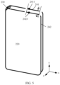
- FIG. 1 is a diagram of a structure of a foldable electronic device 100 according to an embodiment of this application.
- the foldable electronic device 100 may be an electronic device having a foldable function, for example, a mobile phone, a tablet computer, a watch, an e-reader, a notebook computer, or a wearable device.
- the embodiment shown in FIG. 1 is described by using a foldable mobile phone as an example.
- the foldable electronic device 100 may include a flexible display 110, a first side frame 121, a first cover body 122, a second side frame 123, a second cover body 124, and a hinge 125.
- the first side frame 121, the first cover body 122, the second side frame 123, and the second cover body 124 may form a first housing 126 and a second housing 127 that support the flexible display 110.
- at least one of the first cover body 122 and the second cover body 124 may be a display.
- a dot matrix pattern filled in FIG. 1 schematically indicates the flexible display 110.
- the flexible display 110 may be strongly flexile and bendable, to provide a user with a new interaction manner based on a bendable property.
- a display panel of the flexible display 110 may be, for example, any one of a liquid crystal display (liquid crystal display, LCD), an organic light-emitting diode (organic light-emitting diode, OLED), an active-matrix organic light-emitting diode (active-matrix organic light-emitting diode, AMOLED), a flexible light-emitting diode (flexible light-emitting diode, FLED), or quantum dot light emitting diode (quantum dot light emitting diode, QLED). This is not limited.
- the flexible display 110 may include a first display portion 111 corresponding to the first housing 126, a second display portion 112 corresponding to the second housing 127, and a foldable display portion 113 corresponding to the hinge 125.
- the foldable display portion 113 is connected between the first display portion 111 and the second display portion 112.
- the first side frame 121 may surround a periphery of the first cover body 122, and at least a part of the first side frame 121 may further surround a periphery of the first display portion 111.
- the first display portion 111 and the first cover body 122 may be located on two sides of the first side frame 120, and the first display portion 111 and the first cover body 122 may be disposed in parallel and spaced from each other.
- a spacing between the first display portion 111 and the first cover body 122 may be used to dispose a component of the foldable electronic device 100, for example, an antenna or a circuit board component.
- the second side frame 123 may surround a periphery of the second cover body 124, and at least a part of the second side frame 123 may further surround a periphery of the second display portion 112.
- the second display portion 112 and the second cover body 124 may be located on two sides of the second side frame 123, and the second display portion 112 and the second cover body 124 may be disposed in parallel and spaced from each other.
- a spacing between the second display portion 112 and the second cover body 124 may be used to dispose a component of the foldable electronic device 100, for example, an antenna or a circuit board component.
- a cover body and a frame may be two parts of a housing of the foldable electronic device 100.
- the cover body is connected to the frame, and a connection form may include but is not limited to an assembly manner like clamping, adhesion, welding, riveting, or clearance fit.
- a connection relationship between the cover and the frame is usually difficult to be split.
- a cover body and a frame may be two different components. The cover body and the frame are assembled together to form a housing of the foldable electronic device 100.
- the hinge 125 may be connected between the first housing 126 and the second housing 127. Under an action of the hinge 125, the first housing 126 and the second housing 127 may be close to or away from each other. Correspondingly, the first display portion 111 of the flexible display 110 and the second display portion 112 of the flexible display 110 may be close to or far away from each other, so that the flexible display 110 may be folded or unfolded.
- the hinge 125 may include, for example, a main shaft, a first connection component, and a second connection component.
- the first connection component may be fastened to the first cover body 122
- the second connection component may be fastened to the second cover body 124
- the first connection component and the second connection component may rotate relative to the main shaft.
- Mutual movement of the first connection component and the second connection component may drive mutual movement of the first housing 126 and the second housing 127, to implement an opening and closing function of the foldable electronic device 100.
- the first housing 126 may be a housing on a side on which a primary display of the foldable electronic device 100 is located, and the second housing 127 may be a housing on a side on which a secondary display of the foldable electronic device 100 is located.
- the first housing 126 may be a housing on a side on which a secondary display of the foldable electronic device 100 is located, and the second housing 127 may be a housing on a side on which a primary display of the foldable electronic device 100 is located. This is not limited in this application.
- first housing 126 is a housing on a side on which a primary display of the foldable electronic device 100 is located
- second housing 127 is a housing on a side on which a secondary display of the foldable electronic device 100 is located.
- the foldable electronic device 100 shown in FIG. 1 is currently in an unfolded state.
- an angle between the first housing 126 and the second housing 127 may be approximately 180°.
- the flexible display 110 may be in the unfolded state shown in FIG. 1 .
- FIG. 2 shows a possible folded state of the foldable electronic device 100.
- FIG. 2 shows an outward folded state (the outward folded state may be referred to as an out-folded state for short) of the foldable electronic device 100.
- the outward folded state shown in FIG. 2 may be, for example, a left-right outward folded state or an up-down outward folded state.
- the following describes a possible folded state of the foldable electronic device 100.
- that the foldable electronic device 100 is in a folded state may mean that the foldable electronic device 100 is currently bent, and the foldable electronic device 100 reaches a maximum bent degree.
- the first cover body 122 and the second cover body 124 may be in parallel, spaced from each other, and disposed face-to-face, a spacing distance between the first cover body 122 and the second cover body 124 is minimum, and at least a part of the first housing 126 and at least a part of the second housing 127 are accommodated in space enclosed by the flexible display 110; and the first display portion 111, the first housing 126, the second housing 127, and the second display portion 112 are sequentially stacked.
- first display portion 111 and the second display portion 112 may be parallel to each other and spaced from each other, and the spacing distance between the first cover body 122 and the second cover body 124 is less than a spacing distance between the first display portion 111 and the second display portion 112.
- first display portion 111 and the second display portion 112 may be considered to be located on different planes.
- the first cover body 122 and the second cover body 124 may be close to each other, and the first display portion 111 and the second display portion 112 may be close to each other.
- the first display portion 111, the second display portion 112, and the foldable display portion 123 may form a housing accommodation area used to accommodate the first cover body 122, the second cover body 124, and the hinge 125.
- the first cover body 122, the second cover body 124, and the hinge 125 may be accommodated in space of a spacing between the first display portion 111 and the second display portion 112.
- the foldable electronic device 100 may switch between a folded state and an unfolded state. When the foldable electronic device 100 is in a folded state, space occupied by the foldable electronic device 100 is small. When the foldable electronic device 100 is in an unfolded state, the foldable electronic device 100 may display a large screen, to increase a view range available for a user.
- a main body on a secondary display side may directly cover a main body on a primary display side, for example, the second housing 127 directly covers the first housing 126.
- embodiments of this application provide a foldable electronic device, to improve antenna performance of the foldable electronic device in a folded state.
- FIG. 3 and FIG. 4 each are a diagram of a structure of a foldable electronic device 200 according to an embodiment of this application.
- FIG. 3 is a diagram of a structure of the foldable electronic device 200 in an unfolded state.
- FIG. 4 is a diagram of a structure of the foldable electronic device 200 in a folded state. It should be understood that the foldable electronic device 200 may be the foldable electronic device 100.
- the foldable electronic device 200 may include a first housing 210, a second housing 220, a hinge 230, and an antenna 240.
- the hinge 230 may be located between the first housing 210 and the second housing 220, and the hinge 230 is rotatably connected to the first housing 210 and the second housing 220 separately, so that the first housing 210 and the second housing 220 can rotate relative to each other along the hinge 230, that is, the foldable electronic device 200 can switch between an unfolded state and a folded state.
- first housing 210 is a housing on a side on which a primary display of the foldable electronic device 200 is located
- second housing 220 is a housing on a side on which a secondary display of the foldable electronic device 200 is located.
- first housing 210 may alternatively be a housing on a side on which a secondary display of the foldable electronic device 200 is located
- second housing 220 is a housing on a side on which a primary display of the foldable electronic device 200 is located. This is not limited in this application.
- an extension direction of the hinge 230 is parallel to a length direction (direction y) of the foldable electronic device 200.
- this embodiment of this application is described by using an example in which the foldable electronic device 200 is a foldable electronic device that can be folded leftward and rightward.
- an extension direction of the hinge 230 may be parallel to a width direction (direction x) of the foldable electronic device 200, that is, the foldable electronic device 200 may be a foldable electronic device that can be folded upward and downward. This is not limited in this application.
- the first housing 210 may include a first side frame 211, and the second housing 220 includes a second side frame 221.
- the antenna 240 may include a first radiator 241 and a second radiator 242, the first radiator 241 may include a part of the first side frame 211, and the second radiator 242 may include a part of the second side frame 221.
- the first radiator 241 is disposed at the first housing 210, and the second radiator 242 is disposed at the second housing 220.
- a feed point 2411 is disposed on the first radiator 241, and is configured to feed the antenna 240.
- the feed point 2411 may be connected to a radio frequency source 250 of the foldable electronic device, to receive a radio frequency signal output by the radio frequency source 250.
- the length L2 of the second radiator 242 may be greater than the length L1 of the first radiator 241, that is, L2>L1.
- L2 may be equal to 1.2L1, 1.5L1, 1.7L1, 1.8L1, or 2L1. It may be understood that the foregoing specific numerical relationship between L2 and L1 is merely an example, and is not a limitation on this application. The specific numerical relationship may be adjusted according to an actual production and design requirement.
- the first radiator 241 and the second radiator 242 are disposed opposite to each other at a first spacing 243, and at least a part of the first radiator 241 overlaps the second radiator 242, so that the first radiator 241 is coupled to the second radiator 242.
- the first radiator 241 and the second radiator 242 are disposed opposite to each other, and a coupling capacitance is formed between the first radiator 241 and the second radiator 242, to excite the second radiator 242 to generate an excitation resonance signal.
- the second radiator 242 may be used as a parasitic stub of the first radiator 241.
- a size of the first spacing 244 may depend on an overlapping length/a coupling length L3 of the first radiator 241 and the second radiator 242 in a folded state. For example, when the coupling length L3 between the first radiator 241 and the second radiator 242 is small, to ensure the coupling strength, the size of the first spacing 244 may be reduced.
- the coupling length L3 between the first radiator 241 and the second radiator 242 may be greater than 1/2 of the length L1 of the first radiator 241. It should be understood that a range of the coupling length L3 between the first radiator 241 and the second radiator 242 is merely an example, and may be adjusted according to an actual production and design requirement. For example, in some other embodiments, when the foldable electronic device 200 is in a folded state, L3 may alternatively be less than 1/2 of the length L1 of the first radiator 241. This is not limited in this application.
- radio frequency energy of the first radiator 241 can be transferred to the second radiator 242 through coupling, to excite the second radiator 242 to generate radiation, so that the second radiator 242 serves as the parasitic stub and operates together with the first radiator 241.
- the length L2 of the second radiator 242 is set to be greater than the length L1 of the first radiator 241. This helps further improve a radiation capability of the second radiator 242, to improve a radiation capability of the radio frequency energy transferred by the first radiator 241 to the second radiator 242 through coupling. In this way, radiation efficiency of the first radiator 241 can be improved, and an operating bandwidth of the antenna can be extended. This helps reduce adverse impact on antenna performance caused by a reduced ground plane size or overlapping coverage of the housings in a folded state, to improve the antenna performance of the foldable electronic device 200 in a folded state, so that the foldable electronic device 200 has a good radiation characteristic.
- the length L2 of the second radiator 242 and the length L1 of the first radiator 241 may satisfy: L2 ⁇ 1.5L1.
- the first side frame 211 may have a first location 2111 and a second location 2112.
- the first radiator 241 may include the first side frame 211 between the first location 2111 and the second location 2112.
- the first radiator 241 may include the part of the first side frame 211 between the first location 2111 and the second location 2112, and the part of the first side frame 211 may be a conductive side frame.
- the first radiator 241 may further include an internal conductor (for example, a liquid crystal polymer) of the part of the first side frame 211 between the first location 2111 and the second location 2112, and the part of the first side frame 211 may be a non-conductive side frame.
- an internal conductor for example, a liquid crystal polymer
- the first side frame 211 may include a first side 212 and a second side 213 that intersect at an angle, and the first side 212 may be parallel to the extension direction of the hinge 230.
- the first location 2111 and the second location 2112 both are located on the first side 212; or the first location 2111 and the second location 2112 both are located on the second side 213.
- the first radiator 241 may be located on a wide side (in the direction x) or a long side (in the direction y) of the first housing 210. In other words, the first radiator 241 is in a straight line shape.
- the first location 2111 is located on the first side 212, and the second location 2112 is located on the second side 213; or the first location 2111 is located on the second side 213, and the second location 2112 is located on the first side 212.
- the first radiator 241 may be located on both a wide side (in the direction x) and a long side (in the direction y) of the first housing 210. In other words, the first radiator 241 is in a straight line shape. The following embodiments may also be understood correspondingly.
- the first location 2111 is located in an intersection area between the first side 212 and the second side 213; or the second location 2112 is located in an intersection area between the first side 212 and the second side 213.
- first side 212 and the second side 213 may have an overlapping area.
- the overlapping area may be understood as the intersection area between the first side 212 and the second side 213.
- an arc-shaped frame may be understood as the overlapping area/intersection area of the first side 212 and the second side 213.
- the overlapping area/intersection area of the first side 212 and the second side 213 may be understood as an area whose distance to the intersection is within a first threshold (for example, 3 mm).
- a first threshold for example, 3 mm
- the second side frame 221 may have a third location 2211 and a fourth location 2212.
- the second radiator 242 may include the second side frame 221 between the third location 2211 and the fourth location 2212.
- the second side frame 221 may include a third side 222 and a fourth side 223 that intersect at an angle, and the third side 222 may be parallel to the extension direction of the hinge 230.
- the third location 2211 and the fourth location 2212 both are located on the third side 222; or the third location 2211 and the fourth location 2212 both are located on the fourth side 223.
- the second radiator 242 may be located on a wide side (in the direction x) or a long side (in the direction y) of the second housing 220.
- the third location 2211 is located on the third side 222, and the fourth location 2212 is located on the fourth side 223; or the third location 2211 is located on the fourth side 223, and the fourth location 2212 is located on the third side 222.
- the second radiator 242 may be located on both a wide side (in the direction x) or a long side (in the direction y) of the second housing 220.
- the third location 2211 is located in an intersection area between the third side 222 and the fourth side 223; or the fourth location 2212 is located in an intersection area between the third side 222 and the fourth side 223.
- a location of the first radiator 241 on the first side frame 211 and a location of the second radiator 242 on the second side frame 221 are not specially limited, provided that in a folded state, the first radiator 241 can be coupled to the second radiator 242 and the length L2 of the second radiator 242 is greater than the length L1 of the first radiator 241.
- the first radiator 241 may have a first end 2412 and a second end 2413.
- the first end 2412 may be a ground end, and is configured to ground the first radiator 241, and the second end 2413 may be an open end that is not grounded.
- the feed point 2411 may be at a location that is on the first radiator 241 and that is close to the second end 2413, and is connected to the radio frequency source 250.
- the first side frame 211 may separately provide a gap at the first location 2111 and the second location 2112, to form the first end 2412 and the second end 2413 of the first radiator 241, and the first side frame 211 between the two gaps forms the first radiator 241.
- first end 2412 and the second end 2413 on the first side frame 211 may be determined based on actual settings of the first location 2111 and the second location 2112. For example, the first end 2412 and the second end 2413 both are located on the first side 212; or the first end 2412 and the second end 2413 both are located on the second side 213.
- the second radiator 242 may have a third end 2421 and a fourth end 2422.
- the third end 2421 may be a ground end, and is configured to ground the second radiator 242, and the fourth end 2422 may be an open end that is not grounded.
- the second side frame 221 may separately provide a gap at the third location 2211 and the fourth location 2212, to form the third end 2421 and the fourth end 2422 of the second radiator 242, and the second side frame 221 between the two gaps forms the second radiator 242.
- third end 2421 and the fourth end 2422 on the second side frame 221 may be determined based on actual settings of the third location 2211 and the fourth location 2212. For example, the third end 2421 and the fourth end 2422 both are located on the third side 222; or the third end 2421 and the fourth end 2422 both are located on the fourth side 223.
- an electrical length of the second radiator 242 is a quarter of an operating wavelength of the second radiator 242, that is, the second radiator 242 is a quarter-wave antenna.
- the electrical length may be expressed by multiplying a physical length (namely, a mechanical length or a geometric length) by a ratio of transmission time of an electrical or electromagnetic signal in a medium to time required by the signal to travel, in free space, for a distance that is the same as the physical length of the medium.
- the electrical length may be a ratio of a physical length (namely, a mechanical length or a geometric length) to a wavelength of a transmitted electromagnetic wave.
- the antenna 240 may further include a switching circuit 243.
- One end 2431 of the switching circuit 243 is grounded, and another end 2432 of the switching circuit 243 is connected to the second radiator 242, to adjust a resonance frequency of the second radiator 242, namely, the parasitic stub, so that the antenna 240 can cover different frequency bands.
- the switching circuit 243 may include a switch component 2433 and a plurality of different matching branches 2434 disposed in parallel.
- the plurality of different matching branches 2434 may include, for example, a matching branch 2434a and a matching branch 2434b.
- One end of the switch component 2433 is grounded, another end of the switch component 2433 separately gates and is connected to one end of the matching branch 2434a and one end of the matching branch 2434b, and another end of the matching branch 2434a and another end of the matching branch 2434b are separately connected to the second radiator 242.
- the one end of the switch component 2433 forms the one end 2431 of the switching circuit 243
- the another end of the matching branch 2434a and the another end of the matching branch 2434b jointly form the another end 2432 of the switching circuit 243.
- the matching branch 2434a and the matching branch 2434b each may include a capacitor, a capacitor, or a 0-ohm resistor.
- the plurality of different matching branches 2434 may alternatively include three, four, or five different matching branches. This is not limited in this application.
- the switch component 2433 may include, for example, but is not limited to, a single-pole double-throw switch or a double-pole double-throw switch.
- switching circuit 243 is merely an example, and may be adjusted according to an actual production and design requirement. This is not limited in this application.
- a connection point 2423 may be disposed on the second radiator 242, and the connection point 2423 may be at a location that is on the second radiator 242 and that is close to the fourth end 2422, and is configured to connect to the another end 2432 of the switching circuit 243.
- a distance D1 between the connection point 2423 and the fourth end 2422 of the second radiator 242 may satisfy: 0 ⁇ D1 ⁇ 1/2L2.
- the distance D1 between the connection point 2423 and the fourth end 2422 may be 1/5L2, 1/4L2, 1/3L2, or 1/2L2. This is not limited in this application.
- a distance D1 between the connection point 2423 and the fourth end 2422 of the second radiator 242 may satisfy: 1/3L2 ⁇ D1 ⁇ 1/2L2.
- the distance D1 between the connection point 2423 and the fourth end 2422 may be 1/3L2, 2/5L2, 3/7L2, or 1/2L2. This is not limited in this application.
- a range that the distance D1 between the connection point 2423 and the fourth end 2422 of the second radiator 242 meets is merely an example, and may be adjusted based on the lengths of the first radiator 241 and the second radiator 242. This is not limited in this application.
- the first location 2111 and the second location 2112 of the first side frame 211 each are at a location that is on the second side 213 and that is away from the hinge 230.
- the first location 2111 is located in the intersection area between the first side 212 and the second side 213, and the second location 2112 is at the location that is on the second side 213 and that is away from the intersection area.
- the first end 2412 of the first radiator 241 is formed in the intersection area between the first side 212 and the second side 213, and is used for grounding; the second end 2413 of the first radiator 241 is formed at a location that is on the second side 213 and that is away from the intersection area; and the feed point 2411 is at the location that is on the first radiator 241 and that is close to the second end 2413.
- the first radiator 241 is located on the wide side (in the direction x) of the foldable electronic device 200, and is in the straight line shape.
- the third location 2211 of the second side frame 221 is located on the third side 222, and the fourth location 2212 of the second side frame 221 is located on the fourth side 223.
- the third end 2421 of the second radiator 242 is formed on the third side 222 and is used for grounding; the fourth end 2422 of the second radiator 242 is formed on the fourth side 223; and the connection point 2423 is at the location that is on the second radiator 242 and that is close to the fourth end 2422.
- the second radiator 242 is located on both the wide side (in the direction x) and the long side (in the direction y) of the foldable electronic device, and is in an L shape.
- the length L2 of the second radiator 242 is twice the length L1 of the first radiator 241, and the distance D1 between the connection point 2423 and the fourth end 2422 is 2/5L2.
- the first radiator 241 and the second radiator 242 are disposed opposite to each other at the first spacing 243, and all the first radiator 241 overlaps the second radiator 242.
- the coupling length L3 between the first radiator 241 and the second radiator 242 is equal to the length L1 of the first radiator 241.
- the size D2 of the first spacing 243 may satisfy: 0.8 mm ⁇ D2 ⁇ 1.8 mm.
- D2 may be 0.8 mm, 1.0 mm, 1.3 mm, or 1.7 mm.
- a specific value of D2 may be determined based on specific data of the coupling length L3 between the first radiator 241 and the second radiator 242. This is not limited in this application.
- FIG. 5 and FIG. 6 are provided for comparison.
- FIG. 5 is a diagram of a structure of a foldable electronic device in a folded state. A difference from the embodiment shown in FIG. 4 lies in that, in an embodiment shown in FIG. 5 , the length of the first radiator 241 is equal to the length of the second radiator 242.
- FIG. 6 is another diagram of a structure of a foldable electronic device in a folded state. A difference from the embodiment shown in FIG. 4 lies in that, in an embodiment shown in FIG. 6 , when the foldable electronic device is in a folded state, the second radiator 242 is used as a parasitic stub of the first radiator 241 and is not grounded.
- FIG. 7 to FIG. 11 are diagrams of simulation results of an antenna in a case in which a foldable electronic device 200 is in a folded state according to an embodiment of this application.
- FIG. 7 is a scalar distribution diagram of a local magnetic field of an antenna on an outer plane at the top of the foldable electronic device in FIG. 4 in a case in which the foldable electronic device is in a folded state, where the outer plane is parallel to a plane xoz.
- FIG. 8 is a vector distribution diagram of a local magnetic field of an antenna on a cross section of the foldable electronic device in FIG. 4 in a case in which the foldable electronic device is in a folded state, where the cross section is parallel to a plane xoz.
- a direction z is parallel to a thickness direction of the foldable electronic device
- a direction x is parallel to a width direction (namely, a horizontal direction) of the foldable electronic device.
- a magnetic field radiation area of the antenna is dispersed into two areas shown in dashed-line boxes in the figure, that is, two areas in which the first radiator 241 and the second radiator 242 are located.
- the second radiator 242 serves as a parasitic stub of the first radiator 241, so that the magnetic field radiation area of the antenna can be dispersed. This is equivalent to increasing the width of the first radiator 241. In this way, a radiation size of the antenna is increased, and antenna performance of the foldable electronic device in a folded state is improved.
- FIG. 9 is a diagram of simulation results of total efficiency and radiation efficiency of an antenna in cases in which the foldable electronic devices shown in FIG. 4 and FIG. 5 are in a folded state.
- the length of the second radiator 242 that is, the length of a parasitic stub, is set to be greater than the length of the first radiator 234, so that the radiation efficiency of the antenna can be further improved, and an operating bandwidth of the antenna can be extended. This helps reduce adverse impact on antenna performance caused by a reduced ground plane size or overlapping coverage of housings in a folded state, to improve the antenna performance of the foldable electronic device in a folded state, so that the foldable electronic device has a good radiation characteristic.
- FIG. 10 is a diagram of structures of a current distribution at a location of a second radiator 242 in cases in which the foldable electronic devices shown in FIG. 4 and FIG. 6 are in a folded state.
- FIG. 11 is a diagram of simulation results of total efficiency and radiation efficiency of an antenna in cases in which the foldable electronic devices shown in FIG. 4 and FIG. 6 are in a folded state.
- (a) in FIG. 10 is a diagram of a structure of a current distribution at a location of the second radiator 242 shown in FIG. 6 .
- (b) in FIG. 10 is a diagram of a structure of a current distribution at a location of the second radiator 242 shown in FIG. 4 .
- a white arrow in the figure indicates a direction of a current on the second radiator 242.
- directions of currents on the second radiator 242, namely, a parasitic stub, have a same direction.
- the second radiator 242 in a folded state, the second radiator 242 is not grounded, and is parasitic in a 1/2 mode (balanced).
- the first radiator 241 is coupled to the second radiator 242 whose electrical length is 1/2 of an operating wavelength.
- the second radiator 242 is not grounded, a connection between the antenna and a ground plane in the foldable electronic device is weak, and it is difficult to use the ground plane for radiation.
- (b) in FIG. 10 in the embodiment shown in FIG.
- directions of currents on the second radiator 242 have a transverse direction and a longitudinal direction.
- the second radiator 242 in a folded state, is parasitic in a 1/4 mode.
- the first radiator 241 is coupled to the second radiator 242 whose electrical length is 1/4 of an operating wavelength.
- the antenna in this mode, because the second radiator 242 is grounded, the antenna can better use a ground plane current to generate radiation.
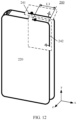
- FIG. 12 is another diagram of a structure of a foldable electronic device 200 in a folded state according to an embodiment of this application.
- a difference from the embodiment shown in FIG. 4 lies in that, when the foldable electronic device 200 is in a folded state, in a thickness direction (direction z) of the foldable electronic device 200, a part of the first radiator 241 overlaps the second radiator 242. In other words, in a folded state, the coupling length L3 between the first radiator 241 and the second radiator 242 is less than the length L1 of the first radiator 241.
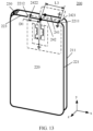
- FIG. 13 is a diagram of a structure of a foldable electronic device 200 in a folded state according to an embodiment of this application.
- a difference from the embodiment shown in FIG. 4 lies in that the third location 2211 and the fourth location 2212 of the second side frame 221 each are located on the fourth side 223.
- the third location 2211 is away from the hinge 230, and the fourth location 2212 is close to the hinge 230.
- the third end 2421 of the second radiator 242 is formed at a location that is on the fourth side 223 and that is away from the hinge 230; the fourth end 2422 is formed at a location that is on the fourth side 223 and that is close to the hinge 230; and the second radiator 242 is in a straight line shape.
- the length L2 of the second radiator 242 is 1.8 times the length L1 of the first radiator 241, and the distance D1 between the connection point 2423 and the fourth end 2422 is 1/3L2.
- the foldable electronic device 200 When the foldable electronic device 200 is in a folded state, in a thickness direction (direction z) of the foldable electronic device 200, all the first radiator 241 overlaps the second radiator 242. In other words, in a folded state, the coupling length L3 between the first radiator 241 and the second radiator 242 is equal to the length L1 of the first radiator 241.
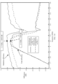
- FIG. 14 is a diagram of simulation results of total efficiency and radiation efficiency of an antenna in cases in which the foldable electronic devices shown in FIG. 13 and FIG. 5 are in a folded state.
- the radiation efficiency of the antenna in FIG. 13 is improved by 1.2238 dB.
- the length of the second radiator 242 that is, the length of a parasitic stub, is set to be greater than the length of the first radiator 234, so that the radiation efficiency of the antenna can be further improved, and an operating bandwidth of the antenna can be extended.
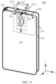
- FIG. 15 is another diagram of a structure of a foldable electronic device 200 in a folded state according to an embodiment of this application.
- a difference from the embodiment shown in FIG. 13 lies in that the first location 2111 and the second location 2112 of the first side frame 211 each are at a location that is on the second side 213 and that is close to the hinge 230.
- the first location 2111 is away from the hinge 230, and the second location 2112 is close to the hinge 230.
- the length L2 of the second radiator 242 is 1.5 times the length L1 of the first radiator 241, and the distance D1 between the connection point 2423 and the fourth end 2422 is 1/3L2.
- the foldable electronic device 200 When the foldable electronic device 200 is in a folded state, in a thickness direction (direction z) of the foldable electronic device 200, all the first radiator 241 overlaps the second radiator 242. In other words, in a folded state, the coupling length L3 between the first radiator 241 and the second radiator 242 is equal to the length L1 of the first radiator 241.
- FIG. 16 is a diagram of simulation results of total efficiency and radiation efficiency of an antenna in cases in which the foldable electronic devices shown in FIG. 15 and FIG. 5 are in a folded state.
- the radiation efficiency of the antenna in FIG. 4 is improved by 0.8972 dB.
- the length of the second radiator 242 that is, the length of a parasitic stub, is set to be greater than the length of the first radiator 234, so that the radiation efficiency of the antenna can be further improved, and an operating bandwidth of the antenna can be extended.
- FIG. 17 is another diagram of a structure of a foldable electronic device 200 in a folded state according to an embodiment of this application.
- a difference from the embodiment shown in FIG. 15 lies in that the third location 2211 and the fourth location 2212 of the second side frame 221 are interchanged on the fourth side 223.
- the third location 2211 is at a location that is on the fourth side 223 and that is close to the hinge 230
- the fourth location 2212 is at a location that is on the fourth side 223 and that is away from the hinge 230.
- the third end 2421 of the second radiator 242 is formed at a location that is on the fourth side 223 and that is close to the hinge 230
- the fourth end 2422 is formed at a location that is on the fourth side 223 and that is away from the hinge 230.
- the length L2 of the second radiator 242 is 1.8 times the length L1 of the first radiator 241, and the distance D1 between the connection point 2423 and the fourth end 2422 is 1/3L2.
- the foldable electronic device 200 When the foldable electronic device 200 is in a folded state, in a thickness direction (direction z) of the foldable electronic device 200, all the first radiator 241 overlaps the second radiator 242. In other words, in a folded state, the coupling length L3 between the first radiator 241 and the second radiator 242 is equal to the length L1 of the first radiator 241.
- FIG. 18 is a diagram of simulation results of total efficiency and radiation efficiency of an antenna in cases in which the foldable electronic devices shown in FIG. 17 and FIG. 5 are in a folded state.
- the radiation efficiency of the antenna in FIG. 18 is improved by 1.5592 dB.
- the length of the second radiator 242 that is, the length of a parasitic stub, is set to be greater than the length of the first radiator 234, so that the radiation efficiency of the antenna can be further improved, and an operating bandwidth of the antenna can be extended.
- FIG. 19 is a diagram of simulation results of an S parameter of an antenna in cases in which the foldable electronic devices shown in FIG. 17 and FIG. 5 are in a folded state;
- a resonance bandwidth of the antenna in the embodiment shown in FIG. 17 is greater than a resonance bandwidth of the antenna in the embodiment shown in FIG. 5 .
- the length of the second radiator 242 that is, the length of a parasitic stub, is set to be greater than the length of the first radiator 234, so that the resonance bandwidth of the antenna can be further extended.
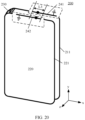
- FIG. 20 is another diagram of a structure of a foldable electronic device 200 in a folded state according to an embodiment of this application.
- a difference from the embodiment shown in FIG. 17 lies in that, when the foldable electronic device 200 is in a folded state, in a thickness direction (direction z) of the foldable electronic device 200, a part of the first radiator 241 overlaps the second radiator 242. In other words, in a folded state, the coupling length L3 between the first radiator 241 and the second radiator 242 is less than the length L1 of the first radiator 241.
- the coupling length L3 between the first radiator 241 and the second radiator 242 may be further less than 1/2 of the length L1 of the first radiator 241.
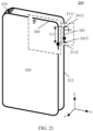
- FIG. 21 is another diagram of a structure of a foldable electronic device 200 in a folded state according to an embodiment of this application.
- a difference from the embodiment shown in FIG. 4 lies in that the first location 2111 and the second location 2112 of the first side frame 211 each are located on the first side 212.
- the first end 2412 and the second end 2413 of the first radiator 241 each are formed on the first side 212.
- the first radiator 241 is located on a long side (in a direction y) of the foldable electronic device 200, and is in a straight line shape.
- the foldable electronic device 200 When the foldable electronic device 200 is in a folded state, in a thickness direction (direction z) of the foldable electronic device 200, all the first radiator 241 overlaps the second radiator 242. In other words, in a folded state, the coupling length L3 between the first radiator 241 and the second radiator 242 is equal to the length L1 of the first radiator 241.
- FIG. 22 is another diagram of a structure of a foldable electronic device 200 in a folded state according to an embodiment of this application.
- a difference from the embodiment shown in FIG. 21 lies in that, when the foldable electronic device 200 is in a folded state, in a thickness direction (direction z) of the foldable electronic device 200, a part of the first radiator 241 overlaps the second radiator 242. In other words, in a folded state, the coupling length L3 between the first radiator 241 and the second radiator 242 is less than the length L1 of the first radiator 241.
- the location layout of the first radiator 241 on the first side frame 211 and the location layout of the second radiator 242 on the second side frame 221 are merely examples, and may be adjusted according to an actual production and design requirement. This is not limited in this application.
Landscapes
- Engineering & Computer Science (AREA)
- Computer Hardware Design (AREA)
- Signal Processing (AREA)
- General Engineering & Computer Science (AREA)
- Computer Networks & Wireless Communication (AREA)
- Telephone Set Structure (AREA)
- Support Of Aerials (AREA)
Applications Claiming Priority (2)
| Application Number | Priority Date | Filing Date | Title |
|---|---|---|---|
| CN202310125196.6A CN116315584A (zh) | 2023-01-20 | 2023-01-20 | 一种可折叠电子设备 |
| PCT/CN2023/135497 WO2024152761A1 (fr) | 2023-01-20 | 2023-11-30 | Dispositif électronique pliable |
Publications (2)
| Publication Number | Publication Date |
|---|---|
| EP4557510A1 true EP4557510A1 (fr) | 2025-05-21 |
| EP4557510A4 EP4557510A4 (fr) | 2025-12-17 |
Family
ID=86827882
Family Applications (1)
| Application Number | Title | Priority Date | Filing Date |
|---|---|---|---|
| EP23917229.9A Pending EP4557510A4 (fr) | 2023-01-20 | 2023-11-30 | Dispositif électronique pliable |
Country Status (3)
| Country | Link |
|---|---|
| EP (1) | EP4557510A4 (fr) |
| CN (2) | CN116315584A (fr) |
| WO (1) | WO2024152761A1 (fr) |
Families Citing this family (10)
| Publication number | Priority date | Publication date | Assignee | Title |
|---|---|---|---|---|
| CN116315584A (zh) * | 2023-01-20 | 2023-06-23 | 华为技术有限公司 | 一种可折叠电子设备 |
| CN116863828B (zh) * | 2023-07-31 | 2026-03-17 | 维沃移动通信有限公司 | 电子设备 |
| CN119481711B (zh) * | 2023-08-10 | 2025-11-28 | 北京小米移动软件有限公司 | 可折叠电子设备 |
| CN120414046B (zh) * | 2023-12-29 | 2026-04-17 | 华为技术有限公司 | 一种可折叠电子设备 |
| CN120432856A (zh) * | 2024-02-04 | 2025-08-05 | 华为技术有限公司 | 一种可折叠电子设备 |
| CN120262005A (zh) * | 2024-04-28 | 2025-07-04 | 华为技术有限公司 | 一种电子设备 |
| CN121192411A (zh) * | 2024-06-21 | 2025-12-23 | 华为技术有限公司 | 一种电子设备 |
| CN121262758A (zh) * | 2024-06-25 | 2026-01-02 | 荣耀终端股份有限公司 | 壳体组件以及可折叠终端 |
| CN121603582A (zh) * | 2024-08-19 | 2026-03-03 | 华为技术有限公司 | 一种可折叠设备 |
| WO2026054248A1 (fr) * | 2024-09-06 | 2026-03-12 | 삼성전자주식회사 | Dispositif électronique pliable comprenant un circuit d'impédance et un circuit de commutation |
Family Cites Families (10)
| Publication number | Priority date | Publication date | Assignee | Title |
|---|---|---|---|---|
| CN115939729B (zh) * | 2019-02-22 | 2026-03-10 | 华为技术有限公司 | 天线装置及电子设备 |
| CN111697315B (zh) * | 2019-03-15 | 2022-04-12 | 华为技术有限公司 | 一种可折叠终端设备 |
| CN112751160B (zh) * | 2019-10-31 | 2021-10-15 | 华为技术有限公司 | 可折叠电子设备 |
| CN114597630B (zh) * | 2020-12-03 | 2025-02-21 | 华为技术有限公司 | 可折叠电子设备 |
| CN115377659B (zh) * | 2021-05-17 | 2025-10-21 | 华为技术有限公司 | 天线及可折叠电子设备 |
| CN215911582U (zh) * | 2021-06-23 | 2022-02-25 | 华为技术有限公司 | 折叠终端 |
| CN113991282A (zh) * | 2021-10-22 | 2022-01-28 | Oppo广东移动通信有限公司 | 天线组件以及电子设备 |
| CN115249889B (zh) * | 2022-09-21 | 2023-02-28 | 荣耀终端有限公司 | 可折叠电子设备 |
| CN115579618A (zh) * | 2022-10-11 | 2023-01-06 | Oppo广东移动通信有限公司 | 可折叠电子设备 |
| CN116315584A (zh) * | 2023-01-20 | 2023-06-23 | 华为技术有限公司 | 一种可折叠电子设备 |
-
2023
- 2023-01-20 CN CN202310125196.6A patent/CN116315584A/zh active Pending
- 2023-11-30 EP EP23917229.9A patent/EP4557510A4/fr active Pending
- 2023-11-30 CN CN202380072572.8A patent/CN120113104A/zh active Pending
- 2023-11-30 WO PCT/CN2023/135497 patent/WO2024152761A1/fr not_active Ceased
Also Published As
| Publication number | Publication date |
|---|---|
| CN116315584A (zh) | 2023-06-23 |
| CN120113104A (zh) | 2025-06-06 |
| WO2024152761A1 (fr) | 2024-07-25 |
| EP4557510A4 (fr) | 2025-12-17 |
Similar Documents
| Publication | Publication Date | Title |
|---|---|---|
| EP4557510A1 (fr) | Dispositif électronique pliable | |
| EP4546561A1 (fr) | Structure d'antenne et dispositif électronique | |
| EP4557509A1 (fr) | Dispositif électronique | |
| US12531331B2 (en) | Antenna structure and electronic device | |
| US20240313388A1 (en) | Antenna structure, antenna module, chip, and electronic device | |
| US20250141089A1 (en) | Electronic device | |
| EP2642595A1 (fr) | Dispositif d'antenne, appareil électronique et procédé de communication sans fil | |
| EP4542767A1 (fr) | Dispositif électronique pliable | |
| CN114512797B (zh) | 天线装置及电子设备 | |
| US12614849B2 (en) | Electronic device | |
| EP4648226A1 (fr) | Structure d'antenne et dispositif électronique | |
| US20250004424A1 (en) | Wearable device | |
| CN118232026A (zh) | 一种天线结构和电子设备 | |
| JP5521580B2 (ja) | 携帯無線端末 | |
| EP4531205A1 (fr) | Dispositif électronique | |
| EP4528929A1 (fr) | Dispositif électronique | |
| JP2015177454A (ja) | マルチバンドアンテナ | |
| US12562477B2 (en) | Antenna and electronic device | |
| EP4462596A1 (fr) | Structure d'antenne et dispositif électronique | |
| EP4557519A1 (fr) | Structure d'antenne et dispositif électronique | |
| HK40102508A (en) | Antenna structure, antenna module, chip, and electronic device | |
| CN117650360B (zh) | 一种天线结构和电子设备 | |
| WO2021161803A1 (fr) | Dispositif d'antenne | |
| EP4557711A1 (fr) | Dispositif électronique et procédé de commutation d'antenne | |
| US20260128499A1 (en) | Foldable Electronic Device |
Legal Events
| Date | Code | Title | Description |
|---|---|---|---|
| STAA | Information on the status of an ep patent application or granted ep patent |
Free format text: STATUS: THE INTERNATIONAL PUBLICATION HAS BEEN MADE |
|
| PUAI | Public reference made under article 153(3) epc to a published international application that has entered the european phase |
Free format text: ORIGINAL CODE: 0009012 |
|
| STAA | Information on the status of an ep patent application or granted ep patent |
Free format text: STATUS: REQUEST FOR EXAMINATION WAS MADE |
|
| 17P | Request for examination filed |
Effective date: 20250212 |
|
| AK | Designated contracting states |
Kind code of ref document: A1 Designated state(s): AL AT BE BG CH CY CZ DE DK EE ES FI FR GB GR HR HU IE IS IT LI LT LU LV MC ME MK MT NL NO PL PT RO RS SE SI SK SM TR |
|
| A4 | Supplementary search report drawn up and despatched |
Effective date: 20251118 |
|
| RIC1 | Information provided on ipc code assigned before grant |
Ipc: H01Q 1/24 20060101AFI20251112BHEP Ipc: H01Q 1/22 20060101ALI20251112BHEP Ipc: H01Q 1/36 20060101ALI20251112BHEP Ipc: H04M 1/02 20060101ALI20251112BHEP Ipc: H01Q 1/50 20060101ALI20251112BHEP Ipc: H01Q 1/38 20060101ALI20251112BHEP Ipc: H01Q 5/328 20150101ALI20251112BHEP Ipc: H01Q 9/42 20060101ALI20251112BHEP Ipc: H01Q 21/28 20060101ALI20251112BHEP |
|
| DAV | Request for validation of the european patent (deleted) | ||
| DAX | Request for extension of the european patent (deleted) |