EP4557522A1 - Ensemble de lignes doté d'un connecteur enfichable - Google Patents
Ensemble de lignes doté d'un connecteur enfichable Download PDFInfo
- Publication number
- EP4557522A1 EP4557522A1 EP24211206.8A EP24211206A EP4557522A1 EP 4557522 A1 EP4557522 A1 EP 4557522A1 EP 24211206 A EP24211206 A EP 24211206A EP 4557522 A1 EP4557522 A1 EP 4557522A1
- Authority
- EP
- European Patent Office
- Prior art keywords
- section
- connection
- connecting element
- contact carrier
- plug
- Prior art date
- Legal status (The legal status is an assumption and is not a legal conclusion. Google has not performed a legal analysis and makes no representation as to the accuracy of the status listed.)
- Pending
Links
Images


Classifications
-
- H—ELECTRICITY
- H01—ELECTRIC ELEMENTS
- H01R—ELECTRICALLY-CONDUCTIVE CONNECTIONS; STRUCTURAL ASSOCIATIONS OF A PLURALITY OF MUTUALLY-INSULATED ELECTRICAL CONNECTING ELEMENTS; COUPLING DEVICES; CURRENT COLLECTORS
- H01R13/00—Details of coupling devices of the kinds covered by groups H01R12/70 or H01R24/00 - H01R33/00
- H01R13/46—Bases; Cases
- H01R13/52—Dustproof, splashproof, drip-proof, waterproof, or flameproof cases
- H01R13/5205—Sealing means between cable and housing, e.g. grommet
-
- H—ELECTRICITY
- H01—ELECTRIC ELEMENTS
- H01R—ELECTRICALLY-CONDUCTIVE CONNECTIONS; STRUCTURAL ASSOCIATIONS OF A PLURALITY OF MUTUALLY-INSULATED ELECTRICAL CONNECTING ELEMENTS; COUPLING DEVICES; CURRENT COLLECTORS
- H01R13/00—Details of coupling devices of the kinds covered by groups H01R12/70 or H01R24/00 - H01R33/00
- H01R13/46—Bases; Cases
- H01R13/52—Dustproof, splashproof, drip-proof, waterproof, or flameproof cases
- H01R13/5219—Sealing means between coupling parts, e.g. interfacial seal
-
- H—ELECTRICITY
- H01—ELECTRIC ELEMENTS
- H01R—ELECTRICALLY-CONDUCTIVE CONNECTIONS; STRUCTURAL ASSOCIATIONS OF A PLURALITY OF MUTUALLY-INSULATED ELECTRICAL CONNECTING ELEMENTS; COUPLING DEVICES; CURRENT COLLECTORS
- H01R4/00—Electrically-conductive connections between two or more conductive members in direct contact, i.e. touching one another; Means for effecting or maintaining such contact; Electrically-conductive connections having two or more spaced connecting locations for conductors and using contact members penetrating insulation
- H01R4/10—Electrically-conductive connections between two or more conductive members in direct contact, i.e. touching one another; Means for effecting or maintaining such contact; Electrically-conductive connections having two or more spaced connecting locations for conductors and using contact members penetrating insulation effected solely by twisting, wrapping, bending, crimping, or other permanent deformation
- H01R4/18—Electrically-conductive connections between two or more conductive members in direct contact, i.e. touching one another; Means for effecting or maintaining such contact; Electrically-conductive connections having two or more spaced connecting locations for conductors and using contact members penetrating insulation effected solely by twisting, wrapping, bending, crimping, or other permanent deformation by crimping
- H01R4/20—Electrically-conductive connections between two or more conductive members in direct contact, i.e. touching one another; Means for effecting or maintaining such contact; Electrically-conductive connections having two or more spaced connecting locations for conductors and using contact members penetrating insulation effected solely by twisting, wrapping, bending, crimping, or other permanent deformation by crimping using a crimping sleeve
-
- H—ELECTRICITY
- H01—ELECTRIC ELEMENTS
- H01R—ELECTRICALLY-CONDUCTIVE CONNECTIONS; STRUCTURAL ASSOCIATIONS OF A PLURALITY OF MUTUALLY-INSULATED ELECTRICAL CONNECTING ELEMENTS; COUPLING DEVICES; CURRENT COLLECTORS
- H01R13/00—Details of coupling devices of the kinds covered by groups H01R12/70 or H01R24/00 - H01R33/00
- H01R13/02—Contact members
- H01R13/025—Contact members formed by the conductors of a cable end
-
- H—ELECTRICITY
- H01—ELECTRIC ELEMENTS
- H01R—ELECTRICALLY-CONDUCTIVE CONNECTIONS; STRUCTURAL ASSOCIATIONS OF A PLURALITY OF MUTUALLY-INSULATED ELECTRICAL CONNECTING ELEMENTS; COUPLING DEVICES; CURRENT COLLECTORS
- H01R13/00—Details of coupling devices of the kinds covered by groups H01R12/70 or H01R24/00 - H01R33/00
- H01R13/40—Securing contact members in or to a base or case; Insulating of contact members
-
- H—ELECTRICITY
- H01—ELECTRIC ELEMENTS
- H01R—ELECTRICALLY-CONDUCTIVE CONNECTIONS; STRUCTURAL ASSOCIATIONS OF A PLURALITY OF MUTUALLY-INSULATED ELECTRICAL CONNECTING ELEMENTS; COUPLING DEVICES; CURRENT COLLECTORS
- H01R13/00—Details of coupling devices of the kinds covered by groups H01R12/70 or H01R24/00 - H01R33/00
- H01R13/46—Bases; Cases
- H01R13/502—Bases; Cases composed of different pieces
- H01R13/504—Bases; Cases composed of different pieces different pieces being moulded, cemented, welded, e.g. ultrasonic welding, or swaged together
-
- H—ELECTRICITY
- H01—ELECTRIC ELEMENTS
- H01R—ELECTRICALLY-CONDUCTIVE CONNECTIONS; STRUCTURAL ASSOCIATIONS OF A PLURALITY OF MUTUALLY-INSULATED ELECTRICAL CONNECTING ELEMENTS; COUPLING DEVICES; CURRENT COLLECTORS
- H01R13/00—Details of coupling devices of the kinds covered by groups H01R12/70 or H01R24/00 - H01R33/00
- H01R13/46—Bases; Cases
- H01R13/52—Dustproof, splashproof, drip-proof, waterproof, or flameproof cases
- H01R13/521—Sealing between contact members and housing, e.g. sealing insert
-
- H—ELECTRICITY
- H01—ELECTRIC ELEMENTS
- H01R—ELECTRICALLY-CONDUCTIVE CONNECTIONS; STRUCTURAL ASSOCIATIONS OF A PLURALITY OF MUTUALLY-INSULATED ELECTRICAL CONNECTING ELEMENTS; COUPLING DEVICES; CURRENT COLLECTORS
- H01R13/00—Details of coupling devices of the kinds covered by groups H01R12/70 or H01R24/00 - H01R33/00
- H01R13/58—Means for relieving strain on wire connection, e.g. cord grip, for avoiding loosening of connections between wires and terminals within a coupling device terminating a cable
- H01R13/5845—Means for relieving strain on wire connection, e.g. cord grip, for avoiding loosening of connections between wires and terminals within a coupling device terminating a cable the strain relief being achieved by molding parts around cable and connections
-
- H—ELECTRICITY
- H01—ELECTRIC ELEMENTS
- H01R—ELECTRICALLY-CONDUCTIVE CONNECTIONS; STRUCTURAL ASSOCIATIONS OF A PLURALITY OF MUTUALLY-INSULATED ELECTRICAL CONNECTING ELEMENTS; COUPLING DEVICES; CURRENT COLLECTORS
- H01R4/00—Electrically-conductive connections between two or more conductive members in direct contact, i.e. touching one another; Means for effecting or maintaining such contact; Electrically-conductive connections having two or more spaced connecting locations for conductors and using contact members penetrating insulation
- H01R4/10—Electrically-conductive connections between two or more conductive members in direct contact, i.e. touching one another; Means for effecting or maintaining such contact; Electrically-conductive connections having two or more spaced connecting locations for conductors and using contact members penetrating insulation effected solely by twisting, wrapping, bending, crimping, or other permanent deformation
- H01R4/18—Electrically-conductive connections between two or more conductive members in direct contact, i.e. touching one another; Means for effecting or maintaining such contact; Electrically-conductive connections having two or more spaced connecting locations for conductors and using contact members penetrating insulation effected solely by twisting, wrapping, bending, crimping, or other permanent deformation by crimping
- H01R4/183—Electrically-conductive connections between two or more conductive members in direct contact, i.e. touching one another; Means for effecting or maintaining such contact; Electrically-conductive connections having two or more spaced connecting locations for conductors and using contact members penetrating insulation effected solely by twisting, wrapping, bending, crimping, or other permanent deformation by crimping for cylindrical elongated bodies, e.g. cables having circular cross-section
- H01R4/184—Electrically-conductive connections between two or more conductive members in direct contact, i.e. touching one another; Means for effecting or maintaining such contact; Electrically-conductive connections having two or more spaced connecting locations for conductors and using contact members penetrating insulation effected solely by twisting, wrapping, bending, crimping, or other permanent deformation by crimping for cylindrical elongated bodies, e.g. cables having circular cross-section comprising a U-shaped wire-receiving portion
- H01R4/185—Electrically-conductive connections between two or more conductive members in direct contact, i.e. touching one another; Means for effecting or maintaining such contact; Electrically-conductive connections having two or more spaced connecting locations for conductors and using contact members penetrating insulation effected solely by twisting, wrapping, bending, crimping, or other permanent deformation by crimping for cylindrical elongated bodies, e.g. cables having circular cross-section comprising a U-shaped wire-receiving portion combined with a U-shaped insulation-receiving portion
-
- H—ELECTRICITY
- H01—ELECTRIC ELEMENTS
- H01R—ELECTRICALLY-CONDUCTIVE CONNECTIONS; STRUCTURAL ASSOCIATIONS OF A PLURALITY OF MUTUALLY-INSULATED ELECTRICAL CONNECTING ELEMENTS; COUPLING DEVICES; CURRENT COLLECTORS
- H01R4/00—Electrically-conductive connections between two or more conductive members in direct contact, i.e. touching one another; Means for effecting or maintaining such contact; Electrically-conductive connections having two or more spaced connecting locations for conductors and using contact members penetrating insulation
- H01R4/70—Insulation of connections
-
- H—ELECTRICITY
- H01—ELECTRIC ELEMENTS
- H01R—ELECTRICALLY-CONDUCTIVE CONNECTIONS; STRUCTURAL ASSOCIATIONS OF A PLURALITY OF MUTUALLY-INSULATED ELECTRICAL CONNECTING ELEMENTS; COUPLING DEVICES; CURRENT COLLECTORS
- H01R13/00—Details of coupling devices of the kinds covered by groups H01R12/70 or H01R24/00 - H01R33/00
- H01R13/40—Securing contact members in or to a base or case; Insulating of contact members
- H01R13/405—Securing in non-demountable manner, e.g. moulding, riveting
-
- H—ELECTRICITY
- H01—ELECTRIC ELEMENTS
- H01R—ELECTRICALLY-CONDUCTIVE CONNECTIONS; STRUCTURAL ASSOCIATIONS OF A PLURALITY OF MUTUALLY-INSULATED ELECTRICAL CONNECTING ELEMENTS; COUPLING DEVICES; CURRENT COLLECTORS
- H01R43/00—Apparatus or processes specially adapted for manufacturing, assembling, maintaining, or repairing of line connectors or current collectors or for joining electric conductors
- H01R43/20—Apparatus or processes specially adapted for manufacturing, assembling, maintaining, or repairing of line connectors or current collectors or for joining electric conductors for assembling or disassembling contact members with insulating base, case or sleeve
Definitions
- the present invention relates to a cable harness with a connector according to the preamble of claim 1.
- Connectors form the electrical connection component between different modules and devices in many electrical and electronic devices as well as industrial production systems.
- Plug-in connections significantly support the simple and rapid interchangeability of various devices and manufacturing modules, as well as the installation of complex and potentially meshed infrastructures. Plug-in connections not only transmit power and signals but also form interfaces for data transmission.
- a cable harness according to the invention with a connector comprises a cable with at least one core line that is electrically connected to a connecting element, wherein the connecting element is arranged in a continuous receptacle in a contact carrier of the connector.
- a first connecting section of the connecting element, with which the at least one core line is fastened to the connecting element, has a first outer diameter that corresponds to an inner diameter of a connection receptacle of the continuous receptacle of the contact carrier.
- the contact carrier of the connector is a cylindrical component with a longitudinal axis, a connection side for the at least one wire and a plug side.
- the contact carrier has a connection section, a plug section, a circumferential collar, an edge section, a first end face of the connection side, a second end face of the plug side, and at least one continuous receptacle for the connecting element.
- the contact carrier can advantageously be manufactured simply as an injection-molded part from an electrically insulating plastic.
- a further embodiment provides that a seal, at least a spray-through prevention of the overmolding compound, is formed between the first connecting section of the connecting element and the contact carrier by means of a narrow gap or a press fit between the first outer diameter of the first connecting section of the connecting element and the corresponding inner diameter of the connection receptacle of the continuous receptacle of the contact carrier.
- This seal as a type of gap seal, is advantageously simple to form and requires no additional sealing components, especially since it is a static application.
- a distance between the outside of the first connecting section and the inside of the connection receptacle is in a range of 0.05 mm excess to 0.1 mm gap, since this enables simple sealing.
- Yet another embodiment provides for a free end of the first connecting section to have a front end formed with a uniform, stable, largely circumferential, accessible mounting edge, with the other end of the first connecting section transitioning into a bent section.
- the largely circumferential mounting edge does not always have to be closed in its circumference, as this depends on the thickness of the conductor. This provides an advantageously simple way to quickly install the connecting element in the contact carrier. This can be done manually and/or mechanically using an assembly tool.
- the offset portion of the first connecting portion has a second outer diameter that is smaller than the first outer diameter of the first connecting portion. This allows even stranded wires with a smaller conductor cross-section to be advantageously attached to the connecting element.
- the offset section of the first connecting section has a second outer diameter that is equal to the first outer diameter of the first connecting section. This advantageously allows the use of single-core cables with a larger conductor cross-section, while the offset section also provides a sealing effect.
- a seal to the wire insulation of the wire cables is formed by the offset section of the connecting element towards the inside of the continuous receptacle of the contact carrier of the connector.
- a connection section of the contact carrier is surrounded in its end region on the connection side by an end section of an insulating body.
- the insulating body also surrounds the at least one free conductor of the cable and an end region of the cable and firmly connects the plug connection to the insulating body. This enables an advantageously simple sealing of the contact carrier on the connection side.
- Another embodiment provides for the insulating body to be formed from an overmolding compound. This is advantageous because it allows for different insulating body shapes, particularly for handling and strain relief.
- the overmolding compound is in contact with an outer side of the connection section in the first quarter of the contact carrier, with the contact carrier, with the edge section, the mounting edge of the connecting element, and with the at least one wire secured in the first connection section, thus forming a seal of the connecting element to the outside on the connection side of the connector.
- the uniform, stable mounting edge which is accessible almost all the way around, is aligned with the edge section of the contact carrier's connection side. This is advantageous for sealing the contact carrier, the single-core cable, the connecting element, and the continuous mounting of the contact carrier.
- the largely circumferential mounting edge does not always have to be closed in its circumference, as this depends on the conductor thickness.
- the connecting element to be a crimp element, with the first connecting section being an insulation crimp, a second connecting section being a conductor crimp, and a contact section being a receptacle or a pin.
- Crimp elements are advantageous stamped/bent parts because they are cost-effective and form commercially available components of high quality.
- the connecting element can be a turned part. This is advantageous for special designs, for example, and expands the range of applications.
- Fig. 1 shows a schematic perspective view of an embodiment of a cable harness 10 according to the invention.
- the cable set 10 comprises a cable 1, with at least one core cable 2 and a contact unit KE.
- the cable 1 has four core wires 2.
- Each core wire 2 is an electrical conductor 3 with insulation.
- the electrical conductor 3 can be a (single) wire or a stranded conductor.
- the contact unit KE has at least one electrically conductive connecting element 4 for connecting a wire 2 to an electrically conductive pole of a connector (not shown).
- a connector can be a socket element or a plug element.
- each wire 2 of the cable 1 is assigned a connecting element 4.
- Each connecting element 4 is designed with a plug-in sleeve for contacting a contact in a mating connector (e.g. socket or plug) and has a first connecting section 4a and a second connecting section 4b for connection to a respective wire cable 2.
- a mating connector e.g. socket or plug
- the connecting element 4 is designed as a crimp element.
- other designs are also possible, such as a turned part.
- the first connecting section 4a is an insulation crimp and the second connecting section 4b is a conductor crimp.
- the first connecting section 4a forms a mechanical fastening of a holding section 2a of the insulated wire cable 2 in the end region of the insulation of the wire cable 2.
- a stripped end section of the conductor 3 of the wire cable 2 is mechanically and electrically conductively fastened by a crimping or pressing process.
- the second connecting section 4b is electrically conductively connected in one piece to a contact section 4c, which here forms the plug-in sleeve.
- the connecting element 4 can also be provided with a plug element, e.g., a plug pin, as the contact section 4c.
- the contact unit KE is designed for installation in a contact carrier 7. This is described further below.
- Fig. 2 shows a schematic perspective view of a connecting element 4 of the embodiment according to Fig. 1 .
- Fig. 3 is a schematic enlarged perspective view of the area III of the connecting element 4 according to Fig. 2 shown.
- FIG. 2 The connecting element 4 is shown prior to assembly.
- the first connecting section 4a and the second connecting section 4b are connected to each other by a first connecting web 4d.
- the contact section 4c is attached to the second connecting section 4b via a second connecting web 4e.
- An outwardly projecting projection 4h is formed on the second connecting web 4e. This projection 4h serves to fix the connecting element 4 when inserting or pushing it into the contact carrier 7 and is described below in connection with Fig. 6 explained further.
- a free end of the first connecting section 4a has an end face.
- the first connecting sections 4a are formed on this end face with a uniform, stable, largely circumferentially accessible mounting edge 4g.
- the largely circumferential mounting edge does not always have to be closed in its circumference, as this depends on the thickness of the conductor.
- the other end of the first connecting section 4a transitions into a cranked section 4f, which in turn is connected to the second connecting section 4e.
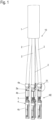
- Fig. 4 shows a schematic enlarged perspective view of the area IV of the embodiment according to Fig. 1 .
- the core wire 2 of the cable 1 is attached, i.e., fastened, to the connecting element 4.
- the core wire 2 is mechanically fastened with its holding section 2a in the end region of its insulation in the first connecting section 4a by crimping or pressing the first connecting section 4a and crimping or pressing the offset section 4f.
- a first end region 5 of the first connecting section 4a below the mounting edge 4g has a fixed outer diameter, which is always manufactured with the same outer diameter. This will be explained in more detail below.
- a second end region 5a of the first connecting section 4a in the offset section 4f has an outer diameter that is smaller than the outer diameter in the first end region 5 of the first connecting section 4a. This is due to the dimensions of the single-core cable 2, since different conductor cross-sections and insulation thicknesses are possible.
- One end of the holding section 2a with the end of the insulation protrudes from the offset section 4f above the first connecting web 4d to the second connecting section 4c.
- the stripped end portion of the conductor 3 is also connected to the second connecting portion 4c by crimping or pressing.
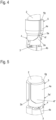
- Fig. 5 shows a schematic enlarged perspective view of a section of a connecting element 4 of a variant of the embodiment according to Fig. 1 represents.
- the connecting element 4 of the variant is for a single conductor 2 with larger dimensions (conductor cross-section, insulation thickness) than those of the single conductor 2 of the embodiment according to Fig. 1 and Fig. 4 provided.
- the crimping or pressing is in Fig. 5
- the outer diameter of the first end region 5 near the mounting edge 4g corresponds to the outer diameter of the first end region 5 of the embodiment according to Fig. 1 and 4 .
- the outer diameter of the second end region 5'a of the first connecting section 4a in the offset section 4'f has the same outer diameter as the first end region 5 of the first connecting section 4a.
- the first connecting section 4a has the same outer diameter in all regions.
- the offset section 4'f is designed without an offset and rests against the holding region 2a of the insulation of the core cable 2.
- Fig. 6-8 show schematic views of the embodiment of a connector 6 according to the invention of the embodiment according to Fig. 1 .
- Fig. 6 a schematic sectional view of the connector 6 with the wire cables 2 of the cable set 10 is shown.
- Fig. 7 shows a perspective view of the connector 6 with the cable set 10 Fig. 6 represents.
- Fig. 8 shows the view of the connector 6 after Fig. 7 with an assembly tool 11.
- the contact unit KE with the connecting elements 4 of the cable set 10 is mounted in a contact carrier 7 of a connector 6 using an assembly tool 11 ( Fig. 8 ) mounted.
- the contact carrier 7 is a cylindrical component with a longitudinal axis 7a, a connection side AN for the conductors 2, and a plug side ST.
- the contact carrier 7 has a connection section 7b, a plug section 7c, a circumferential collar 7d, an edge section 7e of a first end face of the connection side AN, and a second end face 7f of the plug side ST.
- the contact carrier is made of an insulating material, e.g. plastic.
- connection section 7b extends in the direction of the longitudinal axis 7a and then transitions into the plug-in section 7c.
- the transition between the connection section 7b and the plug-in section 7c is surrounded by the circumferential, radially outwardly projecting collar 7d.
- the contact carrier 7 has four continuous receptacles 8, which run parallel to the longitudinal axis 7a of the contact carrier from a first end face with the edge portion 7e to an opposite second plug-in end face 7f.
- the continuous receptacles 8 each serve to accommodate the connecting elements 4.
- Each of the continuous receptacles 8 has a connection receptacle 8a in the region of the connection section 7a of the contact carrier 7 and a plug receptacle 8b in the region of the plug-in section 7c of the contact carrier 7.
- the connection receptacle 8a and the plug receptacle 8b merge into one another in the region of the circumferential collar 7d.
- the connecting elements 4 with the attached conductors 2 of the cable 1 are inserted from the connection side AN into the respective through-holes 8.
- an assembly tool 11 with a bevelled assembly end with an opening 11a is used ( Fig. 8 ), which exerts pressure on the mounting edge 4g of the connecting element 4 during insertion.
- the opening 11a is shaped for the wire 2 in order to enclose it and prevent damage.
- the assembly of the connecting elements 4 can be done manually and/or mechanically.
- the continuous receptacles 8 are formed with a circular cross-section in the contact carrier 7 and are designed such that the projection 4h of a respective connecting element 4 engages in a recess 8c in the region of the transition of a respective connection receptacle 8a and the associated connector receptacle 8b and thus fixes the associated connecting element 4 in a fixed position in the respective continuous receptacle 8.
- the connecting elements 4 When the connecting elements 4 are mounted, i.e. inserted and fixed, in the through-hole receptacles 8, the first connecting sections 4a and second connecting sections 4b are each arranged in the terminal receptacle 8a, wherein the contact sections 4c are each arranged in the connector receptacle 8b.
- the first connecting sections 4a of the connecting elements 4 with the respective conductor line 2 attached thereto are positioned with their respective end region 5 in the input region of the respective connection receptacle 8a.
- the outer diameter of the end regions 5 corresponds to the inner diameter 9 of the respective connection receptacle 8a. This is shown in Fig. 7-8
- a seal is achieved between the first connecting section 4a of the connecting element 4 and the contact carrier 7.
- a distance between the outer side of the first connecting section 4a and the inner side of the connection receptacle 8a is in a range of 0.05 mm oversize up to 0.1 mm gap.
- the gap can be approximately 0.05 mm.
- the uniform, stable, largely circumferentially accessible mounting edge 4g which here is aligned with the edge section 7e of the contact carrier 7, contributes in particular to such a seal.
- Fig. 9 is a schematic sectional view of the first embodiment of the connector 6 according to the invention according to Fig. 6-8 shown.
- connection section 7b In its end region on the connection side AN, the connection section 7b is surrounded by approximately one-quarter of an end section of an insulating body 12.
- the insulating body 12 also surrounds the free conductors 2 of the cable 1 and an end section of the cable 1. In this way, the plug connection 6 is firmly connected to the insulating body 12.
- the insulating body 12 is formed from an overmolding compound 12a which surrounds the contact carrier 7 of the connector 6, the wire leads 2 extending from the connection side AN of the connector 6 to the cable 1 and an end region of the insulation of the cable 1.
- the overmolding compound 12a is in contact with the outside of the connection section 7b in the first quarter of the contact carrier 7, with the edge section 7e, the mounting edges 4g of each connecting element 4 and the wire leads 2 fastened in the first connecting sections 4a and thus forms a seal of the connecting elements 4 to the outside on the connection side AN of the connector 6.
- a seal is achieved by the wire insulation of the holding sections 2a of the wire cables 2 through the respective offset section 4f of the associated connecting element 4. This is achieved, depending on the insulation diameter of the holding section 2a of the wire cables 2, by the contact or pressing of the respective offset section 4f.
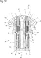
- Fig. 10 shows a schematic sectional view of a variant of the embodiment of the connector 6 according to the invention according to Fig. 9 , wherein an outer diameter of the wire insulation of the holding sections 2a of the wire lines 2 is larger here than in the embodiment according to Fig. 9
- the outer diameters of the first connecting sections 4a and the Offset sections 4f are of equal size and seal the connecting element 4 against the connection receptacle 8a over the entire length of the first connecting section 4a and offset section 4f.
- the connecting elements 4 can be so-called identical parts for both the embodiment and the variant.
- the connecting elements 4 can be designed as stamped/bent parts or as turned parts.
- the insulating body 12 provides strain relief for the wire leads 2 and the cable 1 in conjunction with the connector 6.
- Cable 1 Single-core cable 2 holding section 2a Director 3 connecting element 4 connecting section 4a, 4b Contact section 4c connecting bridge 4d, 4e Offset section 4f, 4'f Mounting edge 4g projection 4 hours End area 5; 5a, 5'a connectors 6
- Contact carrier 7 Longitudinal axis 7a Connection section 7b Plug-in section 7c collar 7d edge section 7e Plug-in end face 7f Recording 8
Landscapes
- Connector Housings Or Holding Contact Members (AREA)
Applications Claiming Priority (1)
| Application Number | Priority Date | Filing Date | Title |
|---|---|---|---|
| DE102023132087.4A DE102023132087A1 (de) | 2023-11-17 | 2023-11-17 | Leitungssatz mit Steckverbinder |
Publications (1)
| Publication Number | Publication Date |
|---|---|
| EP4557522A1 true EP4557522A1 (fr) | 2025-05-21 |
Family
ID=93429903
Family Applications (1)
| Application Number | Title | Priority Date | Filing Date |
|---|---|---|---|
| EP24211206.8A Pending EP4557522A1 (fr) | 2023-11-17 | 2024-11-06 | Ensemble de lignes doté d'un connecteur enfichable |
Country Status (4)
| Country | Link |
|---|---|
| US (1) | US20250167463A1 (fr) |
| EP (1) | EP4557522A1 (fr) |
| CN (1) | CN120021110A (fr) |
| DE (1) | DE102023132087A1 (fr) |
Citations (4)
| Publication number | Priority date | Publication date | Assignee | Title |
|---|---|---|---|---|
| DE3410461A1 (de) * | 1984-03-22 | 1985-09-26 | Stocko Metallwarenfabriken Henkels Und Sohn Gmbh & Co, 5600 Wuppertal | Steckerbuchse mit isolierstoffummantelung sowie vorrichtung fuer ihre herstellung |
| DE10034502C2 (de) * | 2000-07-15 | 2002-10-31 | Lumberg Karl Gmbh & Co | Elektrischer Steckverbinder |
| DE202012013360U1 (de) * | 2011-11-09 | 2016-07-15 | Lq Mechatronik-Systeme Gmbh | Mehrpolige Steckverbindungseinheit für Dreiphasen-Wechselstromsysteme |
| US20160308301A1 (en) * | 2015-04-20 | 2016-10-20 | Yazaki Corporation | Anti-corrosive material, wire with terminal, and wire harness |
-
2023
- 2023-11-17 DE DE102023132087.4A patent/DE102023132087A1/de active Pending
-
2024
- 2024-11-06 EP EP24211206.8A patent/EP4557522A1/fr active Pending
- 2024-11-12 US US18/944,382 patent/US20250167463A1/en active Pending
- 2024-11-15 CN CN202411630432.0A patent/CN120021110A/zh active Pending
Patent Citations (4)
| Publication number | Priority date | Publication date | Assignee | Title |
|---|---|---|---|---|
| DE3410461A1 (de) * | 1984-03-22 | 1985-09-26 | Stocko Metallwarenfabriken Henkels Und Sohn Gmbh & Co, 5600 Wuppertal | Steckerbuchse mit isolierstoffummantelung sowie vorrichtung fuer ihre herstellung |
| DE10034502C2 (de) * | 2000-07-15 | 2002-10-31 | Lumberg Karl Gmbh & Co | Elektrischer Steckverbinder |
| DE202012013360U1 (de) * | 2011-11-09 | 2016-07-15 | Lq Mechatronik-Systeme Gmbh | Mehrpolige Steckverbindungseinheit für Dreiphasen-Wechselstromsysteme |
| US20160308301A1 (en) * | 2015-04-20 | 2016-10-20 | Yazaki Corporation | Anti-corrosive material, wire with terminal, and wire harness |
Also Published As
| Publication number | Publication date |
|---|---|
| US20250167463A1 (en) | 2025-05-22 |
| CN120021110A (zh) | 2025-05-20 |
| DE102023132087A1 (de) | 2025-05-22 |
Similar Documents
| Publication | Publication Date | Title |
|---|---|---|
| EP2342782B1 (fr) | Connexion par enfichage comportant un élément mâle et un élément femelle, et boîtiers d'adaptateur destinés à recevoir ladite connexion par enfichage | |
| EP1573862B1 (fr) | Raccordement electrique, notamment pour raccorder un conducteur exterieur d'un cable coaxial | |
| EP3627636B1 (fr) | Connecteur enfichable électrique, raccord de modules et ensemble de carte de circuits imprimés | |
| DE19615158A1 (de) | Steckverbinder für ein Kabel mit wenigstens einer Ader | |
| EP1965467B1 (fr) | Contact à fiche à haute intensité et dispositif de connexion à haute intensité | |
| EP2731201B1 (fr) | Connecteur électrique et procede de montage de pièces d'un connecteur électrique | |
| EP3067670A1 (fr) | Composant de connecteur pour un capteur et procede de montage d'un composant de connecteur pour un capteur | |
| EP3930104A1 (fr) | Module de câbles extérieurs, connecteur enfichable électrique et agencement de raccordement électrique | |
| EP4295448B1 (fr) | Élément contact de conducteur intérieur pour connecteur à fiches coudé et procédé de fabrication associé | |
| EP3605746B1 (fr) | Connecteur enfichable ainsi que connexion enfichable doté d'un tel connecteur enfichable | |
| EP3091613A2 (fr) | Dispositif de raccordement pour un conducteur hf, en particulier pour un cable coaxial et procede de fabrication dudit dispositif de raccordement | |
| EP3579346B1 (fr) | Connecteur enfichable électrique pour cartes de circuits imprimés | |
| DE202011002287U1 (de) | Kabelverschraubung für abgeschirmte Leitungen | |
| EP1467441A2 (fr) | Connecteur pour un branchement rapide à technique de pince de serrage | |
| DE102005023977B4 (de) | Vorrichtung und Verfahren zum Herstellen einer Vorrichtung | |
| EP3364507B1 (fr) | Connecteur électrique pour un câble électrique multi-fils | |
| EP2731206A1 (fr) | Connecteur et procédé de montage | |
| DE102023004088B4 (de) | Koaxialverbinder | |
| DE102010039747A1 (de) | Kontaktelement zur Kontaktierung eines Verbrauchers mit einem Steuergerät, Anordnung aus einem Verbraucher und einem Steuergerät, sowie Verfahren zur Montage einer solchen Anordnung | |
| EP4557522A1 (fr) | Ensemble de lignes doté d'un connecteur enfichable | |
| DE102011009929A1 (de) | Steckverbinderteil und Verfahren zum Herstellen eines Steckverbinderteils | |
| EP2993737B1 (fr) | Dispositif de connexion a fiches haute frequence, en particulier dispositif de connexion coaxial pour des prises d'antenne | |
| DE202017107625U1 (de) | Elektrischer Steckverbinder | |
| EP1939987B1 (fr) | Dispositif de contact | |
| AT410614B (de) | Kabelstecker mit einem steckergehäuse und elektrischen kontaktelementen |
Legal Events
| Date | Code | Title | Description |
|---|---|---|---|
| PUAI | Public reference made under article 153(3) epc to a published international application that has entered the european phase |
Free format text: ORIGINAL CODE: 0009012 |
|
| STAA | Information on the status of an ep patent application or granted ep patent |
Free format text: STATUS: THE APPLICATION HAS BEEN PUBLISHED |
|
| AK | Designated contracting states |
Kind code of ref document: A1 Designated state(s): AL AT BE BG CH CY CZ DE DK EE ES FI FR GB GR HR HU IE IS IT LI LT LU LV MC ME MK MT NL NO PL PT RO RS SE SI SK SM TR |
|
| STAA | Information on the status of an ep patent application or granted ep patent |
Free format text: STATUS: REQUEST FOR EXAMINATION WAS MADE |
|
| 17P | Request for examination filed |
Effective date: 20251117 |