EP4557533A1 - Elektrischer verbinder - Google Patents
Elektrischer verbinder Download PDFInfo
- Publication number
- EP4557533A1 EP4557533A1 EP23210356.4A EP23210356A EP4557533A1 EP 4557533 A1 EP4557533 A1 EP 4557533A1 EP 23210356 A EP23210356 A EP 23210356A EP 4557533 A1 EP4557533 A1 EP 4557533A1
- Authority
- EP
- European Patent Office
- Prior art keywords
- lever
- electrical connector
- connector
- latch
- rotation
- Prior art date
- Legal status (The legal status is an assumption and is not a legal conclusion. Google has not performed a legal analysis and makes no representation as to the accuracy of the status listed.)
- Pending
Links
Images




Classifications
-
- H—ELECTRICITY
- H01—ELECTRIC ELEMENTS
- H01R—ELECTRICALLY-CONDUCTIVE CONNECTIONS; STRUCTURAL ASSOCIATIONS OF A PLURALITY OF MUTUALLY-INSULATED ELECTRICAL CONNECTING ELEMENTS; COUPLING DEVICES; CURRENT COLLECTORS
- H01R13/00—Details of coupling devices of the kinds covered by groups H01R12/70 or H01R24/00 - H01R33/00
- H01R13/62—Means for facilitating engagement or disengagement of coupling parts or for holding them in engagement
- H01R13/629—Additional means for facilitating engagement or disengagement of coupling parts, e.g. aligning or guiding means, levers, gas pressure electrical locking indicators, manufacturing tolerances
- H01R13/62933—Comprising exclusively pivoting lever
- H01R13/62944—Pivoting lever comprising gear teeth
-
- H—ELECTRICITY
- H01—ELECTRIC ELEMENTS
- H01R—ELECTRICALLY-CONDUCTIVE CONNECTIONS; STRUCTURAL ASSOCIATIONS OF A PLURALITY OF MUTUALLY-INSULATED ELECTRICAL CONNECTING ELEMENTS; COUPLING DEVICES; CURRENT COLLECTORS
- H01R13/00—Details of coupling devices of the kinds covered by groups H01R12/70 or H01R24/00 - H01R33/00
- H01R13/62—Means for facilitating engagement or disengagement of coupling parts or for holding them in engagement
- H01R13/629—Additional means for facilitating engagement or disengagement of coupling parts, e.g. aligning or guiding means, levers, gas pressure electrical locking indicators, manufacturing tolerances
- H01R13/62933—Comprising exclusively pivoting lever
- H01R13/62955—Pivoting lever comprising supplementary/additional locking means
Definitions
- This invention generally relates to an electrical connector. Particularly it relates to an electrical connector that is connected and disconnected with a corresponding mating connector by operation of a lever of the electrical connector.
- a common "lever-type" electrical connector includes an assembly of a first connector or housing and a second counter connector or header or interface. To mate the connectors together, the assembly has an actuating or assist lever mounted for pivoting on the first connector with pivoting of the lever causing the first and second connectors to shift between unmated and fully mated configurations.
- the actuating lever and the second connector typically have a cam groove and a cam follower arrangement for drawing the second connector into mating condition with the first connector in response to pivoting of the lever.
- Such connectors are commonly used in the automotive industry but sometimes require a complex mechanics.
- lever-type connectors provide significant advantages over connectors without mating aid
- current lever-actuator configurations have problems during the mating operation. For a correct mating the lever has to be in an initial mating position that allows a correct engagement of the lever's connection features with features of the counter connector. If the lever is not in the correct initial mating position no engagement of the connection features may be possible or the lever cannot be actuated.
- the object of the present invention is to overcome the disadvantages of the prior art connectors, particularly provide an electrical connector that easy in use, fail-safe and can be mated and un-mated with little effort.
- At least one of outer side walls further comprise a back-rotation prevention feature that in the pre-mating position prevents the lever from being rotated against the actuating rotation direction.
- the lever is also prevented from a rotation against the lever actuating rotation direction.
- the electrical connector comprises two latches and the counter electrical connector comprises two de-latching protrusions.
- the lever comprises one latch at each sidebar. This doubles the latching force and improves holding the lever in the lever initial position.
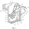
- Fig. 1 shows an electrical connector 1 according to an embodiment of the invention.
- the electrical connector 1 comprises a connector housing 10, a U-shaped lever 20, a pair of first gear wheel elements 30 at the lower end of the lever and a latch 40 that protects the lever 20 from unintentionally movement in lever actuation direction 50.
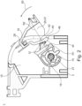
- Figs. 2 and 3A-D show details of the functioning of the latch 40.
- the latch 40 is preferably an integral part of the lever 20 and integrally connected to one of the sidebars 24, 25 via an elastic latch arm 42.
- a lever 20 can preferably have one or two latches 40.
- the latch 40 prevents rotation of the lever 20 from a lever initial position 47 ( Fig. 2 , 3A-B ) to a lever final position 48 ( Fig. 3D ).
- the latch 40 is preferably arranged at the inner side of one of the sidebars 24, 25 for engaging a latching protrusion 12 arranged at one of the side walls 18 of the connector housing 10.
- the latch 40 engages the latching protrusion 12 by means of a latching hook 44 at the free end 46 of the latch arm 42.
- the latch 40 engages the latching protrusion 12 when the connector 1 is in a non-mating position 51 in which the connector is not at all or not sufficiently deep inserted into a counter connector 100 as shown in Figs. 3A-B .
- the latching position of the latch 40 is arranged at a latch radius R1 of 40% to 60% of a crossbar radius R2 of the crossbar around 50 one of the rotation pins 14, 15.
- the latch 40 has a large lever arm for applying a large retention force against unintentional rotation of the lever 20 out of the lever initial position 47.
- the latch 40 When the connector 1 is further pushed from the non-mating position 51 of Fig. 3B into a pre-mating position of Fig. 3C the latch 40 is pushed out of engagement with the latching protrusion 12 by a de-latching protrusion 120 of the counter connector. As shown in Fig. 3C the de-latching protrusion 120 preferably pushes the hook-shaped latch 40 sideways such that its elastic latch arm 42 bends and the latch 40 comes out of engagement with the latching protrusion 12. By de-latching the latch 40 the lever 20 is free to move in lever actuation direction 50. Thus, an assembly person can move the lever 20 in actuation direction 50 such that the teeth of the gear wheel elements 30 engage the teethed racks 102 and draw the connector 1 into fully mated position 54 (see Fig. 3D ).
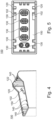
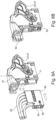
- Figs. 4 and 5 shows further details of the preferred embodiment of the counter connector 100.
- the de-latching protrusion 120 preferably comprises a slanted end 122 that facilitates bending the latch 40 sideways.
- the counter connector 100 comprises a plurality of male electrical terminals 130 of different sizes and shapes. To ensure that only the correct connector 1 mates with counter connector 100 it further comprises coding ridges 140 that correspond to coding slots 32 of the connector 1.
- the housing 10 further comprises at the outer side walls 18 a back-rotation prevention feature 19, preferably in form of a snap hook, that prevents the lever 10) from being rotated against the lever actuating direction 50. As shown in Fig. 2 the back-rotation prevention feature 19 engages a ridge 28 of the lever 20, when the lever is in the lever initial position 47.
- Figs. 6A-6D show the assembly of the lever 20 to the connector housing 10.
- the sidebars 24, 25 of the lever 20 are bent outwards and the lever 20 is pushed onto the connector housing 10 wherein the sidebars 24, 25 are aligned with the sidewalls 18 of the connector housing 10.
- pivot openings 26 of the sidebars 24, 25 are slipped onto the rotation pins 14, 15.
- the pivot openings 26 comprise a keyway entries 27 at the outer perimeter of the pivot openings 26 and the pivot pins 14, 15 comprise corresponding rotation pin protrusions 16 at the outer perimeter of the pivot pins 14, 15.
- lever 20 can only be mounted to rotation pins 14, 15 when the rotation pin protrusions 16 are aligned with the keyway entries 27. This is the case, when the lever 20 is in its lever mounting position 49 as shown in Fig. 6D .
- Figs. 7A-B show the further assembly of the lever 20 to the connector housing 10. From the lever mounting position 49 of Fig. 7A the lever 20 is rotated in lever actuation direction 50 as shown be the arrow. Thereby the latch 40 catches the latching protrusion 12 and the back-rotation prevention feature 19 catches the ridge 28. This provides a bi-directional locking of the lever 20. Further, the rotation pin protrusions 16 engage an outer side wall of the sidebars 24, 25 to securely fix the lever 20 to the connector housing 10. Thus, the lever 20 reaches the lever initial position 47 of Fig. 7B .
- lever initial position 47 the lever 20 is securely mounted to the connector housing 10 and cannot rotate. By preventing rotation it is on the one hand ensured that the lever 20 does not separate from the connector housing 10 and that the lever 20 is in the optimal position for the mating of the electrical connector 1 with the counter electrical connector 100. In this lever initial position 47 the connector 1 is ready to be shipped to a harness manufacturer.
- Figs. 8A-B show the further assembly step of inserting a terminal insert 60 with the electrical terminals inside (not shown) and the electrical or optical wires 62 attached.
- the terminals (not shown) are secured within the terminal insert 60 by a terminal position assurance element (TPA) 66.
- TPA terminal position assurance element
- the terminal insert 60 is inserted into an insert cavity 17 from the side of the connector housing 1.
- the terminal insert 60 latches by the snap hooks 64 at both sides of the terminal insert 60 by means of elastic latches 11 with the connector housing 10.
- Figs. 9A-D in combination with Figs. 3A-D show an electrical connector system 200 comprising of a connector 1 and a corresponding counter connector 100. Particularly, these figures show a method for the assembly of the electrical connector system 200. The method comprising the following steps:
- the latch 40 prevents unintended rotation of the lever 20 prior to final assembly and ensures that the lever 20 is held in the perfect position for mating with the counter connector 100.
- the latch 40 also ensures that the electrical connector 1 has been pushed to the necessary amount onto the counter connector 100 as shown by the movement between the non-mating position 51 of Fig. 9B to the pre-mating position 52 of Fig. 9C in which the latch 40 is released by the de-latching protrusion 120 and the electrical connector 1 assumes a perfect position for the actuation of the lever 20.
- a hassle-free assembly of the electrical connector system 200 is ensured.
Landscapes
- Details Of Connecting Devices For Male And Female Coupling (AREA)
Priority Applications (1)
| Application Number | Priority Date | Filing Date | Title |
|---|---|---|---|
| EP23210356.4A EP4557533A1 (de) | 2023-11-16 | 2023-11-16 | Elektrischer verbinder |
Applications Claiming Priority (1)
| Application Number | Priority Date | Filing Date | Title |
|---|---|---|---|
| EP23210356.4A EP4557533A1 (de) | 2023-11-16 | 2023-11-16 | Elektrischer verbinder |
Publications (1)
| Publication Number | Publication Date |
|---|---|
| EP4557533A1 true EP4557533A1 (de) | 2025-05-21 |
Family
ID=88837401
Family Applications (1)
| Application Number | Title | Priority Date | Filing Date |
|---|---|---|---|
| EP23210356.4A Pending EP4557533A1 (de) | 2023-11-16 | 2023-11-16 | Elektrischer verbinder |
Country Status (1)
| Country | Link |
|---|---|
| EP (1) | EP4557533A1 (de) |
Citations (3)
| Publication number | Priority date | Publication date | Assignee | Title |
|---|---|---|---|---|
| US6325647B1 (en) * | 1999-08-17 | 2001-12-04 | Framatome Connectors International | Electrical plug connector |
| US9178307B2 (en) * | 2011-10-26 | 2015-11-03 | Delphi Technologies, Inc. | Connector having a housing with a first tooth system actuated by a second tooth system on a lever |
| US10374356B2 (en) | 2017-05-25 | 2019-08-06 | Tyco Electronics Amp Italia S.R.L. | Electrical connector having telescopic structure |
-
2023
- 2023-11-16 EP EP23210356.4A patent/EP4557533A1/de active Pending
Patent Citations (3)
| Publication number | Priority date | Publication date | Assignee | Title |
|---|---|---|---|---|
| US6325647B1 (en) * | 1999-08-17 | 2001-12-04 | Framatome Connectors International | Electrical plug connector |
| US9178307B2 (en) * | 2011-10-26 | 2015-11-03 | Delphi Technologies, Inc. | Connector having a housing with a first tooth system actuated by a second tooth system on a lever |
| US10374356B2 (en) | 2017-05-25 | 2019-08-06 | Tyco Electronics Amp Italia S.R.L. | Electrical connector having telescopic structure |
Similar Documents
| Publication | Publication Date | Title |
|---|---|---|
| EP1301968B1 (de) | Verbinder mit hebel | |
| CN1113435C (zh) | 带枢销锁的电气接插件 | |
| EP2311151B1 (de) | Prüfbare einsteckverbindung und verfahren zum prüfen des verbindungszustands einer einsteckverbindung | |
| JP6405360B2 (ja) | レセプタクル・キャリアを有するコネクタ組立体 | |
| KR102459124B1 (ko) | 레버를 갖는 전기 커넥터 | |
| EP1672747B1 (de) | Verbinder | |
| CN102709732B (zh) | 连接器端子位置保持装置 | |
| US7255580B2 (en) | Electrical connector and electrical connector assembly having lever assist with latch hold down mechanism | |
| EP0977324B1 (de) | Verbinder mit Hebel | |
| US7553188B2 (en) | Slide lock panel-mount connector | |
| EP0425130A2 (de) | Elektrischer Verbinder mit zusätzlicher schwenkbarer Verriegelung | |
| EP2276123A1 (de) | Verbinder des hebeltyps | |
| JPH10275650A (ja) | 電気コネクタ | |
| EP3593416B1 (de) | Verbinderbaugruppe | |
| EP0510229A1 (de) | Elektrischer Verbinder mit positiver Einrastung | |
| WO2015016771A1 (en) | Dual-motion mating assisted connector | |
| EP1742302B1 (de) | Verbinder, Verbindungseinrichtung und Montageverfahren dafür | |
| US6783380B1 (en) | Low insertion force connector system | |
| EP4557533A1 (de) | Elektrischer verbinder | |
| CN111834788A (zh) | 带有端子锁的电端子壳体 | |
| US12407124B1 (en) | Connector disengage resistance mechanism | |
| CN118633213A (zh) | 连接器 | |
| EP4697524A1 (de) | Elektrischer verbindungsstecker und seine montageverfahren | |
| EP4611183A1 (de) | Verbinder mit in der ausgabeposition verriegeltem hebel, verfahren zur montage und verwendung davon | |
| KR102904457B1 (ko) | 하우징 조립체, 커넥터 및 연결 디바이스 |
Legal Events
| Date | Code | Title | Description |
|---|---|---|---|
| PUAI | Public reference made under article 153(3) epc to a published international application that has entered the european phase |
Free format text: ORIGINAL CODE: 0009012 |
|
| STAA | Information on the status of an ep patent application or granted ep patent |
Free format text: STATUS: THE APPLICATION HAS BEEN PUBLISHED |
|
| AK | Designated contracting states |
Kind code of ref document: A1 Designated state(s): AL AT BE BG CH CY CZ DE DK EE ES FI FR GB GR HR HU IE IS IT LI LT LU LV MC ME MK MT NL NO PL PT RO RS SE SI SK SM TR |
|
| STAA | Information on the status of an ep patent application or granted ep patent |
Free format text: STATUS: REQUEST FOR EXAMINATION WAS MADE |
|
| 17P | Request for examination filed |
Effective date: 20251117 |