EP4557572A1 - Dispositif de commande, circuit de soupape de coupure pourvu d'un dispositif de commande, dispositif de climatisation pourvu d'un dispositif de commande, et procédé de commande - Google Patents
Dispositif de commande, circuit de soupape de coupure pourvu d'un dispositif de commande, dispositif de climatisation pourvu d'un dispositif de commande, et procédé de commande Download PDFInfo
- Publication number
- EP4557572A1 EP4557572A1 EP23856914.9A EP23856914A EP4557572A1 EP 4557572 A1 EP4557572 A1 EP 4557572A1 EP 23856914 A EP23856914 A EP 23856914A EP 4557572 A1 EP4557572 A1 EP 4557572A1
- Authority
- EP
- European Patent Office
- Prior art keywords
- storage unit
- power
- unit
- power storage
- control
- Prior art date
- Legal status (The legal status is an assumption and is not a legal conclusion. Google has not performed a legal analysis and makes no representation as to the accuracy of the status listed.)
- Pending
Links
Images



Classifications
-
- F—MECHANICAL ENGINEERING; LIGHTING; HEATING; WEAPONS; BLASTING
- F25—REFRIGERATION OR COOLING; COMBINED HEATING AND REFRIGERATION SYSTEMS; HEAT PUMP SYSTEMS; MANUFACTURE OR STORAGE OF ICE; LIQUEFACTION SOLIDIFICATION OF GASES
- F25B—REFRIGERATION MACHINES, PLANTS OR SYSTEMS; COMBINED HEATING AND REFRIGERATION SYSTEMS; HEAT PUMP SYSTEMS
- F25B49/00—Arrangement or mounting of control or safety devices
- F25B49/02—Arrangement or mounting of control or safety devices for compression type machines, plants or systems
-
- F—MECHANICAL ENGINEERING; LIGHTING; HEATING; WEAPONS; BLASTING
- F24—HEATING; RANGES; VENTILATING
- F24F—AIR-CONDITIONING; AIR-HUMIDIFICATION; VENTILATION; USE OF AIR CURRENTS FOR SCREENING
- F24F11/00—Control or safety arrangements
- F24F11/30—Control or safety arrangements for purposes related to the operation of the system, e.g. for safety or monitoring
- F24F11/32—Responding to malfunctions or emergencies
- F24F11/36—Responding to malfunctions or emergencies to leakage of heat-exchange fluid
-
- F—MECHANICAL ENGINEERING; LIGHTING; HEATING; WEAPONS; BLASTING
- F24—HEATING; RANGES; VENTILATING
- F24F—AIR-CONDITIONING; AIR-HUMIDIFICATION; VENTILATION; USE OF AIR CURRENTS FOR SCREENING
- F24F11/00—Control or safety arrangements
- F24F11/30—Control or safety arrangements for purposes related to the operation of the system, e.g. for safety or monitoring
- F24F11/46—Improving electric energy efficiency or saving
-
- F—MECHANICAL ENGINEERING; LIGHTING; HEATING; WEAPONS; BLASTING
- F24—HEATING; RANGES; VENTILATING
- F24F—AIR-CONDITIONING; AIR-HUMIDIFICATION; VENTILATION; USE OF AIR CURRENTS FOR SCREENING
- F24F11/00—Control or safety arrangements
- F24F11/88—Electrical aspects, e.g. circuits
-
- F—MECHANICAL ENGINEERING; LIGHTING; HEATING; WEAPONS; BLASTING
- F25—REFRIGERATION OR COOLING; COMBINED HEATING AND REFRIGERATION SYSTEMS; HEAT PUMP SYSTEMS; MANUFACTURE OR STORAGE OF ICE; LIQUEFACTION SOLIDIFICATION OF GASES
- F25B—REFRIGERATION MACHINES, PLANTS OR SYSTEMS; COMBINED HEATING AND REFRIGERATION SYSTEMS; HEAT PUMP SYSTEMS
- F25B41/00—Fluid-circulation arrangements
- F25B41/20—Disposition of valves, e.g. of on-off valves or flow control valves
- F25B41/24—Arrangement of shut-off valves for disconnecting a part of the refrigerant cycle, e.g. an outdoor part
-
- F—MECHANICAL ENGINEERING; LIGHTING; HEATING; WEAPONS; BLASTING
- F25—REFRIGERATION OR COOLING; COMBINED HEATING AND REFRIGERATION SYSTEMS; HEAT PUMP SYSTEMS; MANUFACTURE OR STORAGE OF ICE; LIQUEFACTION SOLIDIFICATION OF GASES
- F25B—REFRIGERATION MACHINES, PLANTS OR SYSTEMS; COMBINED HEATING AND REFRIGERATION SYSTEMS; HEAT PUMP SYSTEMS
- F25B13/00—Compression machines, plants or systems, with reversible cycle
-
- F—MECHANICAL ENGINEERING; LIGHTING; HEATING; WEAPONS; BLASTING
- F25—REFRIGERATION OR COOLING; COMBINED HEATING AND REFRIGERATION SYSTEMS; HEAT PUMP SYSTEMS; MANUFACTURE OR STORAGE OF ICE; LIQUEFACTION SOLIDIFICATION OF GASES
- F25B—REFRIGERATION MACHINES, PLANTS OR SYSTEMS; COMBINED HEATING AND REFRIGERATION SYSTEMS; HEAT PUMP SYSTEMS
- F25B2313/00—Compression machines, plants or systems with reversible cycle not otherwise provided for
- F25B2313/023—Compression machines, plants or systems with reversible cycle not otherwise provided for using multiple indoor units
- F25B2313/0233—Compression machines, plants or systems with reversible cycle not otherwise provided for using multiple indoor units in parallel arrangements
-
- F—MECHANICAL ENGINEERING; LIGHTING; HEATING; WEAPONS; BLASTING
- F25—REFRIGERATION OR COOLING; COMBINED HEATING AND REFRIGERATION SYSTEMS; HEAT PUMP SYSTEMS; MANUFACTURE OR STORAGE OF ICE; LIQUEFACTION SOLIDIFICATION OF GASES
- F25B—REFRIGERATION MACHINES, PLANTS OR SYSTEMS; COMBINED HEATING AND REFRIGERATION SYSTEMS; HEAT PUMP SYSTEMS
- F25B2500/00—Problems to be solved
- F25B2500/22—Preventing, detecting or repairing leaks of refrigeration fluids
- F25B2500/222—Detecting refrigerant leaks
-
- F—MECHANICAL ENGINEERING; LIGHTING; HEATING; WEAPONS; BLASTING
- F25—REFRIGERATION OR COOLING; COMBINED HEATING AND REFRIGERATION SYSTEMS; HEAT PUMP SYSTEMS; MANUFACTURE OR STORAGE OF ICE; LIQUEFACTION SOLIDIFICATION OF GASES
- F25B—REFRIGERATION MACHINES, PLANTS OR SYSTEMS; COMBINED HEATING AND REFRIGERATION SYSTEMS; HEAT PUMP SYSTEMS
- F25B2600/00—Control issues
- F25B2600/02—Compressor control
- F25B2600/025—Compressor control by controlling speed
- F25B2600/0253—Compressor control by controlling speed with variable speed
-
- F—MECHANICAL ENGINEERING; LIGHTING; HEATING; WEAPONS; BLASTING
- F25—REFRIGERATION OR COOLING; COMBINED HEATING AND REFRIGERATION SYSTEMS; HEAT PUMP SYSTEMS; MANUFACTURE OR STORAGE OF ICE; LIQUEFACTION SOLIDIFICATION OF GASES
- F25B—REFRIGERATION MACHINES, PLANTS OR SYSTEMS; COMBINED HEATING AND REFRIGERATION SYSTEMS; HEAT PUMP SYSTEMS
- F25B2600/00—Control issues
- F25B2600/25—Control of valves
- F25B2600/2513—Expansion valves
-
- F—MECHANICAL ENGINEERING; LIGHTING; HEATING; WEAPONS; BLASTING
- F25—REFRIGERATION OR COOLING; COMBINED HEATING AND REFRIGERATION SYSTEMS; HEAT PUMP SYSTEMS; MANUFACTURE OR STORAGE OF ICE; LIQUEFACTION SOLIDIFICATION OF GASES
- F25B—REFRIGERATION MACHINES, PLANTS OR SYSTEMS; COMBINED HEATING AND REFRIGERATION SYSTEMS; HEAT PUMP SYSTEMS
- F25B2600/00—Control issues
- F25B2600/25—Control of valves
- F25B2600/2519—On-off valves
Definitions
- the present disclosure relates to a control device, a shut-off valve circuit provided with the control device, an air-conditioning device provided with the control device, and a control method.
- the shut-off valve in an air-conditioning device provided with a shut-off valve that shuts off the flow of a refrigerant, the shut-off valve has been controlled using power supplied from an external power supply.
- PTL 1 discloses that in an air-conditioning device provided with an external power supply, a shut-off valve, and a power storage unit that is charged by the external power supply, when the supply of the external power supply is stopped, the shut-off valve is operated using power from the power storage unit to shut off the flow of a refrigerant.
- the present disclosure has been made in consideration of the above circumstances, and an object of the present disclosure is to provide a control device that can improve energy efficiency, a shut-off valve circuit provided with the control device, an air-conditioning device provided with the control device, and a control method.
- a control device includes: a power storage unit that is charged by an external power supply; and a control unit that controls power supplied from the external power supply or the power storage unit, and when power is being supplied from the external power supply and an amount of charge in the power storage unit is equal to or greater than a predetermined amount, the control unit drives a load connected to an outside using the power charged in the power storage unit.
- a shut-off valve circuit includes the above-described control device.
- An air-conditioning device includes the above-described control device.
- a control method includes: a step of charging a power storage unit that is charged by an external power supply; and a control step of controlling power supplied from the external power supply or the power storage unit, and in the control step, when power is being supplied from the external power supply and an amount of charge in the power storage unit is equal to or greater than a predetermined amount, control is performed such that a load connected to an outside is driven using the power charged in the power storage unit.
- FIG. 1 illustrates a configuration in which three indoor units 4 are connected to one outdoor unit 2; however, the number of installed outdoor units 2 and the number of connected indoor units 4 are not limited.
- the indoor unit 4 includes an indoor heat exchanger (not shown), an indoor fan (not shown), an electronic expansion valve (not shown), an indoor unit control device (not shown), and the like. Power for operating the indoor unit 4 is supplied from the indoor unit power supply 5.
- the operating conditions of the indoor unit 4 are controlled by an indoor unit control device based on commands input by a user using a remote control 7.
- the outdoor unit control device and the indoor unit control device are configured to be able to transmit and receive information to and from each other, and control the air-conditioning device 1 while transmitting and receiving information.
- the outdoor unit control device controls, for example, the rotation speed of the compressor and the rotation speed of the outdoor fan.
- the indoor unit control device controls, for example, the rotation speed of the indoor fan and the valve opening degree of the electronic expansion valve. The operation of an air-conditioning device is well known and therefore will not be described in detail.
- the shut-off valve kit 6 is connected to the outdoor unit 2 and the indoor unit 4 via the liquid refrigerant pipe 10 and the gas refrigerant pipe 11.
- the shut-off valve kit 6 switches between opening and closing of each valve that shuts off the flow of refrigerant flowing through the gas refrigerant pipe 11 or the liquid refrigerant pipe 10 based on the operating conditions of the air-conditioning device 1.
- the operating conditions of the air-conditioning device 1 are, for example, a comprehensive determination of cooling operation, heating operation, the temperature of the refrigerant circulating within the air-conditioning device 1, and the presence or absence of a refrigerant leak.
- the refrigerant sensors 8 are provided in the respective indoor units 4 and detect whether or not refrigerant is leaking inside the indoor unit 4 or in the installation environment of the indoor unit 4. Specifically, as an example, when the concentration of the refrigerant inside the indoor unit 4 is greater than a predetermined amount, the refrigerant sensor 8 detects that refrigerant is leaking into the indoor unit 4.
- Fig. 2 is a circuit diagram showing an outline of a shut-off valve kit according to an embodiment of the present disclosure.
- the shut-off valve kit 6 includes a control unit 21 which controls the supplied power and controls the drive of the electrically connected actuator, an external power supply 22, a rectification circuit 23, a SW power supply 24, a switching circuit 25, a transistor Tr2, a constant current circuit 26, a power storage unit 27, and a driving power supply 28.
- the shut-off valve kit 6 switches between opening and closing of an electric valve (electronic expansion valve) EV and a solenoid valve SV, which are shut-off valves that shut off the flow of refrigerant circulating through the outdoor unit 2 and each indoor unit 4.
- an electric valve electronic expansion valve
- SV solenoid valve
- the shut-off valve kit 6 determines whether to use any of the power charged in the power storage unit 27 and the power supplied from the external power supply 22, based on the amount of charge in the power storage unit 27.
- the control unit 21 switches ON/OFF of a switching circuit 25 (described later) based on the presence or absence of power supply from the external power supply 22 (described later) and the amount of charge in the power storage unit 27 (described later).
- the control unit 21 switches a power source for driving the control unit 21 by switching ON/OFF of the switching circuit 25.
- the control unit 21 can switch the open/closed states of the electric valve EV and the solenoid valve SV using the power charged in the power storage unit 27, which will be described later.
- a configuration including the control unit 21 and the power storage unit 27 is referred to as a control device 40.
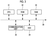
- Fig. 3 is a diagram showing an example of a hardware configuration of the control unit 21 according to an embodiment of the present disclosure.
- the control unit 21 is a computer system and includes, for example, a CPU 31, a read only memory (ROM) 32 for storing programs and the like executed by the CPU 31, a random access memory (RAM) 33 that functions as a work area when each program is executed, a hard disk drive (HDD) 34 as a large-capacity storage device, and a communication unit 35 for connecting to a network or the like.
- ROM read only memory
- RAM random access memory
- HDD hard disk drive
- communication unit 35 for connecting to a network or the like.
- the large-capacity storage device other storage devices such as a solid-state drive (SSD) may also be used.
- SSD solid-state drive
- the control unit 21 may include an input unit including a keyboard and a mouse, or a display unit including a liquid crystal display device for displaying data.
- the external power supply 22 is a power source that supplies power to the shut-off valve kit 6.
- the shut-off valve kit 6 includes a driving power supply 28 for driving the control unit 21, and the control unit 21 is driven using the power supplied to the driving power supply 28.
- the power storage unit 27 is charged with the power supplied from the external power supply 22.
- the rectification circuit 23 is connected in parallel to the external power supply 22 and rectifies the AC voltage supplied from the external power supply 22.
- the rectification circuit 23 is configured with a bridge rectification circuit using rectifier diodes, and performs full-wave rectification on the AC voltage supplied from the external power supply 22.
- the rectification method may be other rectification methods such as half-wave rectification.
- a smoothing capacitor for suppressing pulsating components in the output of the rectification circuit 23 is connected in parallel to a SW power supply 24 (described later) in the output line of the rectification circuit 23.
- the SW power supply 24 is a power supply that stabilizes the output of a DC voltage converted from an AC voltage by controlling the duty ratio of a switching element.
- the SW power supply 24 may include, for example, a DC/DC converter, a switching regulator including an oscillator, and a voltage dividing resistor.
- a rectifier diode and a smoothing capacitor are connected to the output side of the SW power supply 24.
- the switching circuit 25 is a circuit that switches the ON/OFF of the transistor Tr1, which functions as a switch, based on a control signal output from the control unit 21.
- ON/OFF of the transistor Tr1 of the switching circuit 25 is switched, ON/OFF of the transistor Tr2 included in the shut-off valve kit 6 is switched. In this way, the switching circuit 25 performs switching control of the power source that supplies power to the driving power supply 28 (described later) via the control unit 21.
- Resistors r1 and r2 in Fig. 2 are elements for preventing breakdowns in the transistors Tr1 and Tr2, respectively, and for adjusting the voltages applied to the transistors Tr1 and Tr2.
- the constant current circuit 26 is connected to the emitter side of the transistor Tr2, and supplies a constant current to the power storage unit 27.
- the constant current circuit 26 is configured using, for example, a three-terminal regulator IC, and generates a constant current.
- the power storage unit 27 is connected between the output side of the constant current circuit 26 and the rectifier diode.
- the power storage unit 27 is an element that stores power. When the amount of charge in the power storage unit 27 is less than a predetermined amount, the power storage unit 27 charges the power supplied from the external power supply 22. When the charged amount is equal to or greater than a predetermined amount, the battery becomes a power source that supplies power to the driving power supply 28 for driving the control unit 21 under the control to be described below.
- the power storage unit 27 is capable of electric communication with the control unit 21, and the amount of charge in the power storage unit 27 is detected by the control unit 21.
- the power storage unit 27 is, for example, a supercapacitor (electric double layer capacitor).
- Supercapacitors have the characteristic that they can be fully charged in a short time and do not deteriorate easily even when repeatedly charged and discharged.
- the power storage unit 27 may be a secondary battery such as a metal hydride battery, a lithium battery, or a lithium ion battery, thereby increasing the power storage capacity.
- the driving power supply 28 is a power supply that supplies power for driving the control unit 21.
- the driving power supply 28 drives the control unit 21 using the power supplied from the external power supply 22.
- the driving power supply 28 drives the control unit 21 using the power supplied from the power storage unit 27.
- the control unit 21 stops outputting the control signal to the base of the transistor Tr1. At this time, the power storage unit 27 is charged with the power supplied from the external power supply 22 via the constant current circuit 26.
- the driving power supply 28 for driving the control unit 21 is supplied with power from the external power supply 22.
- control unit 21 When the amount of charge in the power storage unit 27 is equal to or greater than a predetermined amount, the control unit 21 outputs a control signal to the base of the transistor Tr1.
- the driving power supply 28 for driving the control unit 21 is not supplied with power from the external power supply 22, but is driven by the supply with the power charged in the power storage unit 27.
- the control unit 21 can control the drive of actuators such as shut-off valves provided outside the shut-off valve kit 6 by using the power charged in the power storage unit 27 even when power is not supplied from the external power supply 22.
- control unit 21 is driven using the power charged in the power storage unit 27 until the amount of charge in the power storage unit 27 falls below a predetermined amount.
- the control unit 21 stops outputting the control signal to the base of the transistor Tr1.
- the driving power supply 28 for driving the control unit 21 switches whether to supply power from the external power supply 22 or the power storage unit 27 depending on the amount of charge in the power storage unit 27.
- Fig. 4 is a table showing the state of the shut-off valves (the electric valve EV and the solenoid valve SV) with respect to operating conditions of the air-conditioning device 1.
- the control unit 21 provided in the shut-off valve kit 6 specifically switches between opening and closing of each valve, namely, the electric valve EV provided in the liquid refrigerant pipe 10 provided in the air-conditioning device 1 and the solenoid valve SV provided in the gas refrigerant pipe 11, based on the operating state of the air-conditioning device 1 or the amount of charge in the power storage unit 27. This controls the flow of refrigerant circulating through the refrigerant circuit of the air-conditioning device 1.
- the power source for controlling the opening and closing of the electric valve EV and the solenoid valve SV is switched based on the amount of charge in the power storage unit 27.
- the amount of charge in the power storage unit 27 is equal to or greater than a predetermined amount (the capacitor charging voltage is equal to or greater than 6 [V])
- the electric valve EV and the solenoid valve SV use the power charged in the power storage unit 27 to bring the electric valve EV and the solenoid valve SV into an open state.
- the amount of charge in the power storage unit 27 is less than a predetermined amount (the capacitor charging voltage is less than 6 [V])
- the electric valve EV and the solenoid valve SV are brought into a closed state.
- the amount of charge in the power storage unit 27 is less than a predetermined amount, the power storage unit 27 is charged with the power supplied from the external power supply 22 via the constant current circuit 26.
- control unit 21 provided in the shut-off valve kit 6 of the indoor unit group 100 switches the electric valve EV and the solenoid valve SV to a closed state.
- the control unit 21 detects the amount of charge in the power storage unit 27, and when the amount of charge in the power storage unit 27 is equal to or greater than a predetermined amount, the control unit 21 controls the switching circuit 25 to supply the power charged in the power storage unit 27 to the driving power supply 28.
- the control unit 21 can switch the electric valve EV and the solenoid valve SV to a closed state.
- the control unit 21 detects the amount of charge in the power storage unit 27, and when the amount of charge in the power storage unit 27 is less than a predetermined amount, the power charged in the power storage unit 27 is not used, and the control unit 21 controls the switching circuit 25 to supply the power supplied from the external power supply 22 to the driving power supply 28.
- the control unit 21 switches the electric valve EV and the solenoid valve SV to a closed state. During that time, the power storage unit 27 is charged with the power supplied from the external power supply 22 until the charged amount reaches or exceeds a predetermined amount.
- control unit 21 can switch whether to perform the opening and closing control of the electric valve EV and the solenoid valve SV using any of the external power supply 22 and the power storage unit 27 as the power source, depending on the operating conditions of the other indoor unit group 200 and the amount of charge in the power storage unit 27. This reduces the standby power consumption of the power storage unit 27 when the power storage unit 27 is fully charged, thereby making it possible to improve the efficiency of power consumption.
- the plurality of indoor units 4 of the indoor unit group 100 each include the refrigerant sensor 8 corresponding to each indoor unit 4.
- Each refrigerant sensor 8 detects the presence or absence of a refrigerant leak inside the corresponding indoor unit 4 or in the installation environment of each indoor unit 4.
- Each refrigerant sensor 8 outputs a detection result of a refrigerant leak inside the corresponding indoor unit 4 or in the installation environment of the indoor unit 4 to the indoor unit 4. Then, the indoor unit 4 corresponding to the refrigerant sensor 8 that detected the refrigerant leak outputs a notification that the refrigerant leak has been detected to the control unit 21 of the shut-off valve kit 6.
- control unit 21 When the control unit 21 receives a notification that a refrigerant leak has been detected inside the indoor unit 4 or in the installation environment of the indoor unit 4, the control unit 21 detects the amount of charge in the power storage unit 27, and when the amount of charge in the power storage unit 27 is equal to or greater than a predetermined amount, the control unit 21 controls the switching circuit 25 to supply the power charged in the power storage unit 27 to the driving power supply 28. When power is supplied from the power storage unit 27 to the driving power supply 28, the control unit 21 can switch the electric valve EV and the solenoid valve SV to a closed state.
- control unit 21 When the control unit 21 receives a notification that a refrigerant leak has been detected inside the indoor unit 4 or in the installation environment of the indoor unit 4, the control unit 21 detects the amount of charge in the power storage unit 27, and when the amount of charge in the power storage unit 27 is less than a predetermined amount, the control unit 21 controls the switching circuit 25 to supply power supplied from the external power supply 22 to the driving power supply 28 without using the power charged in the power storage unit 27.
- the control unit 21 switches the electric valve EV and the solenoid valve SV to a closed state. During that time, the power storage unit 27 is charged with the power supplied from the external power supply 22 until the charged amount reaches or exceeds a predetermined amount.
- control unit 21 when the control unit 21 detects a refrigerant leak inside the indoor unit 4 or in the installation environment of the indoor unit 4 by the refrigerant sensor 8, the control unit 21 can switch whether to perform the opening and closing control of the electric valve EV and the solenoid valve SV using any of the external power supply 22 and the power storage unit 27 as the power source, depending on the amount of charge in the power storage unit 27. This reduces the standby power consumption when the power storage unit 27 is fully charged, thereby making it possible to improve the efficiency of power consumption.
- the electric valve EV and the solenoid valve SV are provided in the liquid refrigerant pipe 10 and the gas refrigerant pipe 11 between the outdoor unit and the shut-off valve kit 6, respectively.
- the present disclosure is not limited to this example, and the electric valve EV and the solenoid valve SV may be provided in positions close to each indoor unit 4 side in the liquid refrigerant pipe 10 and the gas refrigerant pipe 11 between each indoor unit 4 and the shut-off valve kit 6.
- a control device including: a power storage unit (27) that is charged by an external power supply (22); and a control unit (21) that controls power supplied from the external power supply or the power storage unit, in which when power is being supplied from the external power supply and an amount of charge in the power storage unit is equal to or greater than a predetermined amount, the control unit drives a load (EV, SV) connected to an outside using the power charged in the power storage unit.
- a load EV, SV
- control unit can consume the power charged in the power storage unit when a voltage equal to or greater than a predetermined amount is charged in the power storage unit, even in a state in which power is being supplied from an external power supply, thereby reducing standby power consumption and improving energy efficiency.
- the state in which power is being supplied from an external power supply refers to, for example, a state in which power equal to or greater than a predetermined percentage of a preset maximum rated value is being supplied from the external power supply.
- the power storage unit is a supercapacitor.
- the power storage unit is a supercapacitor
- the load is a shut-off valve that is disposed in an inter-unit pipe connecting a refrigerant circuit of an indoor unit and an outdoor unit, and that shuts off a flow of a refrigerant between the refrigerant circuit and the outdoor unit, and when the amount of charge in the power storage unit is equal to or greater than the predetermined amount in a state in which the power is being supplied from the external power supply, the control unit controls an open/closed state of the shut-off valve using the power charged in the power storage unit.
- control unit prioritizes using the power charged in the power storage unit, thereby making it possible to improve the efficiency of power consumption of the system.
- the control unit can close the shut-off valve by using the power charged in the power storage unit. This prevents mist-like refrigerant from flowing back inside the pipe connecting the refrigerant circuit of the indoor unit and the outdoor unit, reducing a likelihood of breakdowns in equipment such as the indoor unit, the outdoor unit, and the compressor provided in the outdoor unit.
- control device (40) according to any one of the first to third aspects further includes a refrigerant detection unit that detects a refrigerant leak, and when the refrigerant detection unit detects a refrigerant leak, the control unit controls the shut-off valve to a closed state using the power charged in the power storage unit.
- the control unit can control the shut-off valve to a closed state using the power charged in the power storage unit. This makes it possible to quickly stop a refrigerant leak regardless of whether or not power is being supplied from an external power supply, thereby suppressing breakdown of the control device or the occurrence of fire accidents.
- a shut-off valve circuit (6) including the control device according to any one of the first to fourth aspects.
- an air-conditioning device (1) including the control device according to any one of the first to fourth aspects.
- a control method including: a step of charging a power storage unit that is charged by an external power supply; and a control step of controlling power supplied from the external power supply or the power storage unit, in which in the control step, when power is being supplied from the external power supply and an amount of charge in the power storage unit is equal to or greater than a predetermined amount, control is performed such that a load connected to an outside is driven using the power charged in the power storage unit.
Landscapes
- Engineering & Computer Science (AREA)
- Mechanical Engineering (AREA)
- General Engineering & Computer Science (AREA)
- Chemical & Material Sciences (AREA)
- Combustion & Propulsion (AREA)
- Physics & Mathematics (AREA)
- Thermal Sciences (AREA)
- Air Conditioning Control Device (AREA)
Applications Claiming Priority (2)
| Application Number | Priority Date | Filing Date | Title |
|---|---|---|---|
| JP2022132492A JP2024029983A (ja) | 2022-08-23 | 2022-08-23 | 制御装置、制御装置を備える遮断弁回路、制御装置を備える空気調和装置及び制御方法 |
| PCT/JP2023/019336 WO2024042795A1 (fr) | 2022-08-23 | 2023-05-24 | Dispositif de commande, circuit de soupape de coupure pourvu d'un dispositif de commande, dispositif de climatisation pourvu d'un dispositif de commande, et procédé de commande |
Publications (2)
| Publication Number | Publication Date |
|---|---|
| EP4557572A1 true EP4557572A1 (fr) | 2025-05-21 |
| EP4557572A4 EP4557572A4 (fr) | 2025-11-05 |
Family
ID=90012854
Family Applications (1)
| Application Number | Title | Priority Date | Filing Date |
|---|---|---|---|
| EP23856914.9A Pending EP4557572A4 (fr) | 2022-08-23 | 2023-05-24 | Dispositif de commande, circuit de soupape de coupure pourvu d'un dispositif de commande, dispositif de climatisation pourvu d'un dispositif de commande, et procédé de commande |
Country Status (3)
| Country | Link |
|---|---|
| EP (1) | EP4557572A4 (fr) |
| JP (1) | JP2024029983A (fr) |
| WO (1) | WO2024042795A1 (fr) |
Families Citing this family (1)
| Publication number | Priority date | Publication date | Assignee | Title |
|---|---|---|---|---|
| JP7758087B2 (ja) * | 2024-03-29 | 2025-10-22 | 株式会社富士通ゼネラル | 空気調和機 |
Family Cites Families (2)
| Publication number | Priority date | Publication date | Assignee | Title |
|---|---|---|---|---|
| JP5209957B2 (ja) * | 2007-12-26 | 2013-06-12 | パナソニック株式会社 | 直流配電システム |
| JP7407374B2 (ja) | 2019-02-19 | 2024-01-04 | パナソニックIpマネジメント株式会社 | 空気調和装置 |
-
2022
- 2022-08-23 JP JP2022132492A patent/JP2024029983A/ja active Pending
-
2023
- 2023-05-24 WO PCT/JP2023/019336 patent/WO2024042795A1/fr not_active Ceased
- 2023-05-24 EP EP23856914.9A patent/EP4557572A4/fr active Pending
Also Published As
| Publication number | Publication date |
|---|---|
| EP4557572A4 (fr) | 2025-11-05 |
| JP2024029983A (ja) | 2024-03-07 |
| WO2024042795A1 (fr) | 2024-02-29 |
Similar Documents
| Publication | Publication Date | Title |
|---|---|---|
| JP2022176373A (ja) | ヒートポンプ装置及び弁キット | |
| EP2309213B1 (fr) | Système de climatisation et procédé de contrôle de son fonctionnement | |
| US11506412B2 (en) | Air conditioner | |
| JPWO2018235230A1 (ja) | 冷凍サイクル装置 | |
| US10784798B2 (en) | Power converting apparatus and home appliance including the same | |
| EP4557572A1 (fr) | Dispositif de commande, circuit de soupape de coupure pourvu d'un dispositif de commande, dispositif de climatisation pourvu d'un dispositif de commande, et procédé de commande | |
| CN107339785A (zh) | 空调系统及其控制方法 | |
| JP7012692B2 (ja) | ヒートポンプ装置及び弁キット | |
| JP4142838B2 (ja) | 空気調和機 | |
| WO2024028946A1 (fr) | Dispositif à cycle de réfrigération | |
| JP6068121B2 (ja) | 空気調和機 | |
| CN104566767A (zh) | 电源电路和空调机组 | |
| JP2012233600A (ja) | 空気調和装置 | |
| US9209705B2 (en) | Power supply circuit and heat pump unit | |
| JP2009240085A (ja) | 発電・空調システム | |
| KR101906965B1 (ko) | Bldc 모터를 이용한 직류 입력형 전산실 냉방시스템 | |
| EP3276283B1 (fr) | Appareil à cycle frigorifique | |
| CN221403406U (zh) | 空调器的控制装置和空调器 | |
| CN216649536U (zh) | 空调室内机的控制电路、空调室内机和空调器 | |
| CN221403405U (zh) | 空调器及其控制装置 | |
| CN223484428U (zh) | 室内机的供电电路和空调器 | |
| KR20110040634A (ko) | 실내기, 이를 포함한 공기 조화기, 및 공기 조화기의 운전 제어 방법 | |
| WO2020053986A1 (fr) | Système de climatisation | |
| WO2025246964A1 (fr) | Système de commande électronique et système de chauffage et de ventilation | |
| WO2025246865A1 (fr) | Système de commande électronique et système de chauffage et de ventilation |
Legal Events
| Date | Code | Title | Description |
|---|---|---|---|
| STAA | Information on the status of an ep patent application or granted ep patent |
Free format text: STATUS: THE INTERNATIONAL PUBLICATION HAS BEEN MADE |
|
| PUAI | Public reference made under article 153(3) epc to a published international application that has entered the european phase |
Free format text: ORIGINAL CODE: 0009012 |
|
| STAA | Information on the status of an ep patent application or granted ep patent |
Free format text: STATUS: REQUEST FOR EXAMINATION WAS MADE |
|
| 17P | Request for examination filed |
Effective date: 20250212 |
|
| AK | Designated contracting states |
Kind code of ref document: A1 Designated state(s): AL AT BE BG CH CY CZ DE DK EE ES FI FR GB GR HR HU IE IS IT LI LT LU LV MC ME MK MT NL NO PL PT RO RS SE SI SK SM TR |
|
| A4 | Supplementary search report drawn up and despatched |
Effective date: 20251002 |
|
| RIC1 | Information provided on ipc code assigned before grant |
Ipc: H02J 9/06 20060101AFI20250926BHEP Ipc: F24F 11/36 20180101ALI20250926BHEP Ipc: F24F 11/46 20180101ALI20250926BHEP Ipc: F24F 11/88 20180101ALI20250926BHEP Ipc: F25B 41/24 20210101ALI20250926BHEP Ipc: F25B 49/02 20060101ALI20250926BHEP |
|
| DAV | Request for validation of the european patent (deleted) | ||
| DAX | Request for extension of the european patent (deleted) |