EP4557632A1 - Betriebsverfahren einer vorrichtung in einem drahtloskommunikationssystem und vorrichtung mit verwendung des verfahrens - Google Patents
Betriebsverfahren einer vorrichtung in einem drahtloskommunikationssystem und vorrichtung mit verwendung des verfahrens Download PDFInfo
- Publication number
- EP4557632A1 EP4557632A1 EP23839899.4A EP23839899A EP4557632A1 EP 4557632 A1 EP4557632 A1 EP 4557632A1 EP 23839899 A EP23839899 A EP 23839899A EP 4557632 A1 EP4557632 A1 EP 4557632A1
- Authority
- EP
- European Patent Office
- Prior art keywords
- ssb
- ncr
- fwd
- index
- ssb index
- Prior art date
- Legal status (The legal status is an assumption and is not a legal conclusion. Google has not performed a legal analysis and makes no representation as to the accuracy of the status listed.)
- Pending
Links
Images






Classifications
-
- H—ELECTRICITY
- H04—ELECTRIC COMMUNICATION TECHNIQUE
- H04B—TRANSMISSION
- H04B7/00—Radio transmission systems, i.e. using radiation field
- H04B7/14—Relay systems
- H04B7/15—Active relay systems
- H04B7/155—Ground-based stations
- H04B7/15528—Control of operation parameters of a relay station to exploit the physical medium
-
- H—ELECTRICITY
- H04—ELECTRIC COMMUNICATION TECHNIQUE
- H04W—WIRELESS COMMUNICATION NETWORKS
- H04W56/00—Synchronisation arrangements
- H04W56/001—Synchronization between nodes
- H04W56/0015—Synchronization between nodes one node acting as a reference for the others
-
- H—ELECTRICITY
- H04—ELECTRIC COMMUNICATION TECHNIQUE
- H04B—TRANSMISSION
- H04B17/00—Monitoring; Testing
- H04B17/30—Monitoring; Testing of propagation channels
- H04B17/309—Measuring or estimating channel quality parameters
- H04B17/318—Received signal strength
- H04B17/328—Reference signal received power [RSRP]; Reference signal received quality [RSRQ]
-
- H—ELECTRICITY
- H04—ELECTRIC COMMUNICATION TECHNIQUE
- H04B—TRANSMISSION
- H04B7/00—Radio transmission systems, i.e. using radiation field
- H04B7/02—Diversity systems; Multi-antenna system, i.e. transmission or reception using multiple antennas
- H04B7/04—Diversity systems; Multi-antenna system, i.e. transmission or reception using multiple antennas using two or more spaced independent antennas
- H04B7/06—Diversity systems; Multi-antenna system, i.e. transmission or reception using multiple antennas using two or more spaced independent antennas at the transmitting station
- H04B7/0686—Hybrid systems, i.e. switching and simultaneous transmission
- H04B7/0695—Hybrid systems, i.e. switching and simultaneous transmission using beam selection
- H04B7/06952—Selecting one or more beams from a plurality of beams, e.g. beam training, management or sweeping
- H04B7/06968—Selecting one or more beams from a plurality of beams, e.g. beam training, management or sweeping using quasi-colocation [QCL] between signals
-
- H—ELECTRICITY
- H04—ELECTRIC COMMUNICATION TECHNIQUE
- H04B—TRANSMISSION
- H04B7/00—Radio transmission systems, i.e. using radiation field
- H04B7/14—Relay systems
- H04B7/15—Active relay systems
- H04B7/155—Ground-based stations
-
- H—ELECTRICITY
- H04—ELECTRIC COMMUNICATION TECHNIQUE
- H04L—TRANSMISSION OF DIGITAL INFORMATION, e.g. TELEGRAPHIC COMMUNICATION
- H04L5/00—Arrangements affording multiple use of the transmission path
- H04L5/003—Arrangements for allocating sub-channels of the transmission path
- H04L5/0048—Allocation of pilot signals, i.e. of signals known to the receiver
-
- H—ELECTRICITY
- H04—ELECTRIC COMMUNICATION TECHNIQUE
- H04W—WIRELESS COMMUNICATION NETWORKS
- H04W16/00—Network planning, e.g. coverage or traffic planning tools; Network deployment, e.g. resource partitioning or cells structures
- H04W16/24—Cell structures
- H04W16/28—Cell structures using beam steering
-
- H—ELECTRICITY
- H04—ELECTRIC COMMUNICATION TECHNIQUE
- H04W—WIRELESS COMMUNICATION NETWORKS
- H04W24/00—Supervisory, monitoring or testing arrangements
- H04W24/02—Arrangements for optimising operational condition
-
- H—ELECTRICITY
- H04—ELECTRIC COMMUNICATION TECHNIQUE
- H04W—WIRELESS COMMUNICATION NETWORKS
- H04W24/00—Supervisory, monitoring or testing arrangements
- H04W24/08—Testing, supervising or monitoring using real traffic
-
- H—ELECTRICITY
- H04—ELECTRIC COMMUNICATION TECHNIQUE
- H04W—WIRELESS COMMUNICATION NETWORKS
- H04W24/00—Supervisory, monitoring or testing arrangements
- H04W24/10—Scheduling measurement reports ; Arrangements for measurement reports
-
- H—ELECTRICITY
- H04—ELECTRIC COMMUNICATION TECHNIQUE
- H04W—WIRELESS COMMUNICATION NETWORKS
- H04W48/00—Access restriction; Network selection; Access point selection
- H04W48/16—Discovering, processing access restriction or access information
-
- H—ELECTRICITY
- H04—ELECTRIC COMMUNICATION TECHNIQUE
- H04W—WIRELESS COMMUNICATION NETWORKS
- H04W72/00—Local resource management
- H04W72/04—Wireless resource allocation
- H04W72/044—Wireless resource allocation based on the type of the allocated resource
- H04W72/0446—Resources in time domain, e.g. slots or frames
-
- H—ELECTRICITY
- H04—ELECTRIC COMMUNICATION TECHNIQUE
- H04W—WIRELESS COMMUNICATION NETWORKS
- H04W72/00—Local resource management
- H04W72/04—Wireless resource allocation
- H04W72/044—Wireless resource allocation based on the type of the allocated resource
- H04W72/046—Wireless resource allocation based on the type of the allocated resource the resource being in the space domain, e.g. beams
-
- H—ELECTRICITY
- H04—ELECTRIC COMMUNICATION TECHNIQUE
- H04W—WIRELESS COMMUNICATION NETWORKS
- H04W72/00—Local resource management
- H04W72/20—Control channels or signalling for resource management
- H04W72/23—Control channels or signalling for resource management in the downlink direction of a wireless link, i.e. towards a terminal
-
- H—ELECTRICITY
- H04—ELECTRIC COMMUNICATION TECHNIQUE
- H04B—TRANSMISSION
- H04B7/00—Radio transmission systems, i.e. using radiation field
- H04B7/02—Diversity systems; Multi-antenna system, i.e. transmission or reception using multiple antennas
- H04B7/04—Diversity systems; Multi-antenna system, i.e. transmission or reception using multiple antennas using two or more spaced independent antennas
- H04B7/06—Diversity systems; Multi-antenna system, i.e. transmission or reception using multiple antennas using two or more spaced independent antennas at the transmitting station
- H04B7/0686—Hybrid systems, i.e. switching and simultaneous transmission
- H04B7/0695—Hybrid systems, i.e. switching and simultaneous transmission using beam selection
-
- H—ELECTRICITY
- H04—ELECTRIC COMMUNICATION TECHNIQUE
- H04B—TRANSMISSION
- H04B7/00—Radio transmission systems, i.e. using radiation field
- H04B7/02—Diversity systems; Multi-antenna system, i.e. transmission or reception using multiple antennas
- H04B7/04—Diversity systems; Multi-antenna system, i.e. transmission or reception using multiple antennas using two or more spaced independent antennas
- H04B7/08—Diversity systems; Multi-antenna system, i.e. transmission or reception using multiple antennas using two or more spaced independent antennas at the receiving station
- H04B7/0868—Hybrid systems, i.e. switching and combining
- H04B7/088—Hybrid systems, i.e. switching and combining using beam selection
-
- H—ELECTRICITY
- H04—ELECTRIC COMMUNICATION TECHNIQUE
- H04W—WIRELESS COMMUNICATION NETWORKS
- H04W74/00—Wireless channel access
- H04W74/08—Non-scheduled access, e.g. ALOHA
- H04W74/0833—Random access procedures, e.g. with 4-step access
-
- H—ELECTRICITY
- H04—ELECTRIC COMMUNICATION TECHNIQUE
- H04W—WIRELESS COMMUNICATION NETWORKS
- H04W84/00—Network topologies
- H04W84/02—Hierarchically pre-organised networks, e.g. paging networks, cellular networks, WLAN [Wireless Local Area Network] or WLL [Wireless Local Loop]
- H04W84/04—Large scale networks; Deep hierarchical networks
- H04W84/042—Public Land Mobile systems, e.g. cellular systems
- H04W84/047—Public Land Mobile systems, e.g. cellular systems using dedicated repeater stations
Definitions
- the present disclosure relates to a method of operating a device in a wireless communication system and a device using the method.
- next-generation communication As a growing number of communication devices require higher communication capacity, there is a need for advanced mobile broadband communication as compared to existing radio access technology (RAT).
- Massive machine-type communication which provides a variety of services anytime and anywhere by connecting a plurality of devices and a plurality of objects, is also one major issue to be considered in next-generation communication.
- designs for communication systems considering services or a user equipment (UE) sensitive to reliability and latency are under discussion.
- UE user equipment
- URLLC ultra-reliable and low-latency communication
- this technology may be referred to as new RAT or new radio (NR).
- a repeater (also referred to as a relay) may be introduced into NR.
- the repeater is network-controlled repeater (NCR).
- NCR may include NCR-MT (mobile termination) and NCR-Fwd (Forwarding).
- the NCR-MT may perform a role of communicating with the base station and controlling the NCR-Fwd.
- the NCR-Fwd performs signal forwarding function. That is, a signal received from a base station can be transmitted to a UE, or a signal received from a UE can be transmitted to the base station.
- An NCR can be located within the coverage of a base station.
- the NCR forwards the essential signals transmitted by the base station, for example, the synchronization signal/physical broadcast channel block (SSB).
- SSB synchronization signal/physical broadcast channel block
- the beam of the backhaul link of NCR-Fwd i.e., the link between the base station and NCR-Fwd
- the beam direction of the backhaul link of the NCR-Fwd can be adjusted to the same.
- the issue may be how to determine the beam direction on the access link of the NCR-Fwd, i.e., the link between the UE and the NCR-Fwd.
- the technical problem to be solved by the present disclosure is to provide a method of operating a device in a wireless communication system and a device using the method.
- the device performs an initial access procedure with a network, receives synchronization signal/physical broadcast channel block (SSB) configuration information from the network and performs a forwarding operation based on the SSB configuration information.
- SSB synchronization signal/physical broadcast channel block
- the device performs the forwarding operation only in a time resource in which an SSB related to a specific SSB index among SSB indexes informed by the SSB configuration information is transmitted.
- the SSB configuration information informs a beam identity (ID) or a transmission configuration indicator (TCI) state related to each SSB index, and the device performs a forwarding operation of the access link using a beam determined based on the beam ID or the TCI state related to the specific SSB index, in a time resource in which an SSB having the specific SSB index is transmitted.
- ID beam identity
- TCI transmission configuration indicator
- signaling overhead in controlling the forwarding operation of NCR can be reduced.
- a or B may mean “only A”, “only B” or “both A and B”.
- a or B may be interpreted as “A and/or B”.
- A, B, or C may mean “only A”, “only B”, “only C”, or "any combination of A, B, C”.
- a slash (/) or comma used in the present specification may mean “and/or”.
- A/B may mean “A and/or B”.
- A/B may mean “only A”, “only B”, or “both A and B”.
- A, B, C may mean “A, B, or C”.
- At least one of A and B may mean “only A”, “only B”, or “both A and B”.
- the expression “at least one of A or B” or “at least one of A and/or B” may be interpreted as "at least one of A and B”.
- At least one of A, B, and C may mean “only A”, “only B”, “only C”, or “any combination of A, B, and C”.
- at least one of A, B, or C or “at least one of A, B, and/or C” may mean “at least one of A, B, and C”.
- a parenthesis used in the present specification may mean “for example”.
- control information PDCCH
- PDCCH control information
- a parenthesis used in the present specification may mean “for example”.
- control information i.e., PDCCH
- PDCCH control information
- a wireless communication system to which the present disclosure may be referred to as an Evolved-UMTS Terrestrial Radio Access Network (E-UTRAN) or a Long Term Evolution (LTE)/LTE-A system, for example.
- E-UTRAN Evolved-UMTS Terrestrial Radio Access Network
- LTE Long Term Evolution
- LTE-A Long Term Evolution
- the E-UTRAN includes at least one base station (BS) which provides a control plane and a user plane to a user equipment (UE).
- the UE may be fixed or mobile, and may be referred to as another terminology, such as a mobile station (MS), a user terminal (UT), a subscriber station (SS), a mobile terminal/termination (MT), a wireless device, terminal, etc.
- the BS is generally a fixed station that communicates with the UE and may be referred to as another terminology, such as an evolved node-B (eNB), a base transceiver system (BTS), an access point, etc.
- eNB evolved node-B
- BTS base transceiver system
- access point etc.
- the BSs are interconnected by means of an X2 interface.
- the BSs are also connected by means of an S1 interface to an evolved packet core (EPC), more specifically, to a mobility management entity (MME) through S1-MME and to a serving gateway (S-GW) through S1-U.
- EPC evolved packet core
- MME mobility management entity
- S-GW serving gateway
- the EPC includes an MME, an S-GW, and a packet data network-gateway (P-GW).
- the MME has access information of the UE or capability information of the UE, and such information is generally used for mobility management of the UE.
- the S-GW is a gateway having an E-UTRAN as an end point.
- the P-GW is a gateway having a PDN as an end point.
- next generation radio access technology considering enhanced mobile broadband communication (eMBB), massive MTC (mMTC), ultrareliable and low latency communication (URLLC) is discussed.
- eMBB enhanced mobile broadband communication
- mMTC massive MTC
- URLLC ultrareliable and low latency communication
- This new technology may be called new radio access technology (new RAT or NR) in the present disclosure for convenience.
- FIG. 1 illustrates a system structure of a next generation radio access network (NG-RAN) to which NR is applied.
- NG-RAN next generation radio access network
- the NG-RAN may include a base station (e.g., gNB and/or an eNB) that provides user plane and control plane protocol termination to a UE.
- FIG. 1 illustrates the case of including only gNBs.
- the gNB and the eNB are connected by an Xn interface.
- the gNB and the eNB are connected to a 5G core network (5GC) via an NG interface.
- 5GC 5G core network
- the gNB and the eNB are connected to an access and mobility management function (AMF) via an NG-C interface and connected to a user plane function (UPF) via an NG-U interface.
- AMF access and mobility management function
- UPF user plane function
- layers of a radio interface protocol between the UE and the network may be classified into a first layer (L1), a second layer (L2), and a third layer (L3) based on the lower three layers of the open system interconnection (OSI) model that is well-known in the communication system.
- a physical (PHY) layer belonging to the first layer provides an information transfer service by using a physical channel
- a radio resource control (RRC) layer belonging to the third layer serves to control a radio resource between the UE and the network.
- the RRC layer exchanges an RRC message between the UE and the BS.
- FIG. 2 is a diagram showing a wireless protocol architecture for a user plane.
- FIG. 3 is a diagram showing a wireless protocol architecture for a control plane.
- the user plane is a protocol stack for user data transmission.
- the control plane is a protocol stack for control signal transmission.
- a PHY layer provides an upper layer with an information transfer service through a physical channel.
- the PHY layer is connected to a medium access control (MAC) layer which is an upper layer of the PHY layer through a transport channel.
- MAC medium access control
- Data is transferred between the MAC layer and the PHY layer through the transport channel.
- the transport channel is classified according to how and with what characteristics data is transferred through a radio interface.
- the physical channel may be modulated according to an Orthogonal Frequency Division Multiplexing (OFDM) scheme, and use the time and frequency as radio resources.
- OFDM Orthogonal Frequency Division Multiplexing
- the functions of the MAC layer include mapping between a logical channel and a transport channel and multiplexing and demultiplexing to a transport block that is provided through a physical channel on the transport channel of a MAC Service Data Unit (SDU) that belongs to a logical channel.
- SDU MAC Service Data Unit
- the MAC layer provides service to a Radio Link Control (RLC) layer through the logical channel.
- RLC Radio Link Control
- the functions of the RLC layer include the concatenation, segmentation, and reassembly of an RLC SDU.
- QoS Quality of Service
- RB Radio Bearer
- the RLC layer provides three types of operation mode: Transparent Mode (TM), Unacknowledged Mode (UM), and Acknowledged Mode (AM).
- TM Transparent Mode
- UM Unacknowledged Mode
- AM Acknowledged Mode
- AM RLC provides error correction through an Automatic Repeat Request (ARQ).
- ARQ Automatic Repeat Request
- the RRC layer is defined only on the control plane.
- the RRC layer is related to the configuration, reconfiguration, and release of radio bearers, and is responsible for control of logical channels, transport channels, and PHY channels.
- An RB means a logical route that is provided by the first layer (PHY layer) and the second layers (MAC layer, the RLC layer, and the PDCP layer) in order to transfer data between UE and a network.
- the function of a Packet Data Convergence Protocol (PDCP) layer on the user plane includes the transfer of user data and header compression and ciphering.
- the function of the PDCP layer on the user plane further includes the transfer and encryption/integrity protection of control plane data.
- PDCP Packet Data Convergence Protocol
- What an RB is configured means a process of defining the characteristics of a wireless protocol layer and channels in order to provide specific service and configuring each detailed parameter and operating method.
- An RB can be divided into two types of a Signaling RB (SRB) and a Data RB (DRB).
- SRB Signaling RB
- DRB Data RB
- the SRB is used as a passage through which an RRC message is transmitted on the control plane
- the DRB is used as a passage through which user data is transmitted on the user plane.
- the UE If RRC connection is established between the RRC layer of UE and the RRC layer of an E-UTRAN, the UE is in the RRC connected state. If not, the UE is in the RRC idle state.
- a downlink transport channel through which data is transmitted from a network to UE includes a broadcast channel (BCH) through which system information is transmitted and a downlink shared channel (SCH) through which user traffic or control messages are transmitted. Traffic or a control message for downlink multicast or broadcast service may be transmitted through the downlink SCH, or may be transmitted through an additional downlink multicast channel (MCH).
- BCH broadcast channel
- SCH downlink shared channel
- Traffic or a control message for downlink multicast or broadcast service may be transmitted through the downlink SCH, or may be transmitted through an additional downlink multicast channel (MCH).
- MCH downlink multicast channel
- an uplink transport channel through which data is transmitted from UE to a network includes a random access channel (RACH) through which an initial control message is transmitted and an uplink shared channel (SCH) through which user traffic or control messages are transmitted.
- RACH random access channel
- SCH uplink shared channel
- Logical channels that are placed over the transport channel and that are mapped to the transport channel include a broadcast control channel (BCCH), a paging control channel (PCCH), a common control channel (CCCH), a multicast control channel (MCCH), and a multicast traffic channel (MTCH).
- BCCH broadcast control channel
- PCCH paging control channel
- CCCH common control channel
- MCCH multicast control channel
- MTCH multicast traffic channel
- the physical channel includes several OFDM symbols in the time domain and several subcarriers in the frequency domain.
- One subframe includes a plurality of OFDM symbols in the time domain.
- An RB is a resources allocation unit, and includes a plurality of OFDM symbols and a plurality of subcarriers.
- each subframe may use specific subcarriers of specific OFDM symbols (e.g., the first OFDM symbol) of the corresponding subframe for a physical downlink control channel (PDCCH), that is, an L1/L2 control channel.
- PDCCH physical downlink control channel
- a Transmission Time Interval (TTI) is a unit time for transmission of subframe.
- FIG. 4 illustrates a functional division between an NG-RAN and a 5GC.
- the gNB may provide functions such as an inter-cell radio resource management (Inter Cell RRM), radio bearer management (RB control), connection mobility control, radio admission control, measurement configuration & provision, dynamic resource allocation, and the like.
- the AMF may provide functions such as NAS security, idle state mobility handling, and so on.
- the UPF may provide functions such as mobility anchoring, PDU processing, and the like.
- the SMF may provide functions such as UE IP address assignment, PDU session control, and so on.
- FIG. 5 illustrates an example of a frame structure that may be applied in NR.
- a radio frame (which may be called as a frame hereinafter) may be used for uplink and downlink transmission in NR.
- a frame has a length of 10 ms and may be defined as two 5 ms half-frames (Half-Frame, HF).
- a half-frame may be defined as five 1 ms subframes (Subframe, SF).
- a subframe may be divided into one or more slots, and the number of slots in a subframe depends on subcarrier spacing (SCS).
- SCS subcarrier spacing
- the symbol may include an OFDM symbol (or a CP-OFDM symbol) and an SC-FDMA symbol (or a DFT-s-OFDM symbol).
- the following table 2 illustrates the number of slots in a frame (N frame, ⁇ slot ), the number of slots in a subframe (N subframe, ⁇ slot ), the number of symbols in a slot (N slot symb ), and the like, according to subcarrier spacing configurations ⁇ .
- OFDM(A) numerologies e.g., SCS, CP length, and so on
- OFDM(A) numerologies may be differently configured between a plurality of cells integrated to one UE.
- an (absolute time) duration of a time resource e.g., SF, slot or TTI
- a time unit e.g., TU
- FIG. 6 illustrates a slot structure
- a slot may comprise a plurality of symbols in a time domain. For example, in case of a normal CP, one slot may include 14 symbols (or 7 symbols). However, in case of an extended CP, one slot may include 12 symbols (or 6 symbols).
- the carrier may include a plurality of subcarriers in a frequency domain.
- a resource block (RB) may be defined as a plurality of consecutive subcarriers (e.g., 12) in the frequency domain.
- a bandwidth part (BWP) may be defined as a plurality of consecutive (P)RBs in the frequency domain, and may correspond to one numerology (e.g., SCS, CP length, etc.).
- a carrier may include a maximum of N (e.g., 5) BWPs. Data communication is performed through the activated BWP, and only one BWP can be activated for one UE.
- Each element in the resource grid is referred to as a resource element (RE), and one complex symbol may be mapped thereto.
- a physical downlink control channel may include one or more control channel elements (CCEs) as illustrated in the following table 3.
- CCEs control channel elements
- the PDCCH may be transmitted through a resource including 1, 2, 4, 8, or 16 CCEs.
- the CCE includes six resource element groups (REGs), and one REG includes one resource block in a frequency domain and one orthogonal frequency division multiplexing (OFDM) symbol in a time domain.
- REGs resource element groups
- OFDM orthogonal frequency division multiplexing
- Monitoring means decoding each PDCCH candidate according to a downlink control information (DCI) format.
- the UE monitors a set of PDCCH candidates in one or more control resource sets (CORESETs, described below) on the activated DL BWP of each activated serving cell for which PDCCH monitoring is configured according to a corresponding search space set.
- CORESETs control resource sets
- a new unit called a control resource set (CORESET) may be introduced in the NR.
- the UE may receive a PDCCH in the CORESET.
- FIG. 7 illustrates a CORESET
- the CORESET includes N CORESET RB resource blocks in the frequency domain, and N CORESET symb ⁇ ⁇ 1, 2, 3 ⁇ number of symbols in the time domain.
- N CORESET RB and N CORESET symb may be provided by a base station via higher layer signaling.
- a plurality of CCEs (or REGs) may be included in the CORESET.
- the UE may attempt to detect a PDCCH in units of 1, 2, 4, 8, or 16 CCEs in the CORESET.
- PDCCH candidates One or a plurality of CCEs in which PDCCH detection may be attempted may be referred to as PDCCH candidates.
- a plurality of CORESETs may be configured for the UE.
- a control region in the conventional wireless communication system (e.g., LTE/LTE-A) is configured over the entire system band used by a base station (BS). All the UEs, excluding some (e.g., eMTC/NB-IoT UE) supporting only a narrow band, should be able to receive wireless signals of the entire system band of the BS in order to properly receive/decode control information transmitted by the BS.
- BS base station
- CORESETs are radio resources for control information to be received by the UE and may use only a portion, rather than the entirety of the system bandwidth in the frequency domain. In addition, in the time domain, only some of the symbols in the slot may be used.
- the BS may allocate the CORESET to each UE and may transmit control information through the allocated CORESET.
- a UE in NR can receive control information of a base station even if it does not necessarily receive the entire system band.
- the CORESET may include a UE-specific CORESET for transmitting UE-specific control information and a common CORESET for transmitting control information common to all UEs.
- NR may require high reliability according to applications.
- a target block error rate (BLER) for downlink control information (DCI) transmitted through a downlink control channel may remarkably decrease compared to those of conventional technologies.
- BLER target block error rate
- content included in DCI can be reduced and/or the amount of resources used for DCI transmission can be increased.
- resources can include at least one of resources in the time domain, resources in the frequency domain, resources in the code domain and resources in the spatial domain.
- FIG. 8 shows an example of a frame structure for a new radio access technology.
- a structure in which a control channel and a data channel are time-division-multiplexed within one TTI can be considered as a frame structure in order to minimize latency.
- a hatched area indicates a downlink control area
- a black area indicates an uplink control area.
- the unmarked area may be used for downlink data (DL data) transmission or uplink data (UL data) transmission.
- DL data downlink data
- UL data uplink data
- a feature of this structure is that downlink (DL) transmission and uplink (UL) transmission are sequentially performed within one subframe and thus DL data can be transmitted and UL ACK/NACK (Acknowledgement/negative-acknowledgement) can be received within the subframe. Consequently, a time required from occurrence of a data transmission error to data retransmission is reduced, thereby minimizing latency in final data transmission.
- a time gap for a base station and a UE to switch from a transmission mode to a reception mode or from the reception mode to the transmission mode may be required.
- some OFDM symbols at a time when DL switches to UL may be set to a guard period (GP) in the self-contained subframe structure.
- FIG. 9 illustrates a structure of self-contained slot.
- one slot includes all of a DL control channel, DL or UL data channel, UL control channel, and so on.
- the first N symbols in a slot may be used for transmitting a DL control channel (in what follows, DL control region), and the last M symbols in the slot may be used for transmitting an UL control channel (in what follows, UL control region).
- N and M are each an integer of 0 or larger.
- a resource region located between the DL and UL control regions (in what follows, a data region) may be used for transmission of DL data or UL data.
- one slot may correspond to one of the following configurations. Each period is listed in the time order.
- a PDCCH may be transmitted, and in the DL data region, a PDSCH may be transmitted.
- a PUCCH may be transmitted, and in the UL data region, a PUSCH may be transmitted.
- DCI Downlink Control Information
- DL data scheduling information for example, DL data scheduling information or UL data scheduling information
- UCI Uplink Control Information
- ACK/NACK Positive Acknowledgement/Negative Acknowledgement
- CSI Channel State Information
- SR Scheduling Request
- a GP provides a time gap during a process where a gNB and a UE transition from the transmission mode to the reception mode or a process where the gNB and UE transition from the reception mode to the transmission mode.
- Part of symbols belonging to the occasion in which the mode is changed from DL to UL within a subframe may be configured as the GP.
- Wavelengths are shortened in millimeter wave (mmW) and thus a large number of antenna elements can be installed in the same area. That is, the wavelength is 1 cm at 30 GHz and thus a total of 100 antenna elements can be installed in the form of a 2-dimensional array at an interval of 0.5 lambda (wavelength) in a panel of 5 ⁇ 5 cm. Accordingly, it is possible to increase a beamforming (BF) gain using a large number of antenna elements to increase coverage or improve throughput in mmW.
- BF beamforming
- TXRU transceiver unit
- independent beamforming per frequency resource can be performed.
- installation of TXRUs for all of about 100 antenna elements decreases effectiveness in terms of cost. Accordingly, a method of mapping a large number of antenna elements to one TXRU and controlling a beam direction using an analog phase shifter is considered.
- Such analog beamforming can form only one beam direction in all bands and thus cannot provide frequency selective beamforming.
- Hybrid beamforming (BF) having a number B of TXRUs which is smaller than Q antenna elements can be considered as an intermediate form of digital BF and analog BF.
- the number of directions of beams which can be simultaneously transmitted are limited to B although it depends on a method of connecting the B TXRUs and the Q antenna elements.
- hybrid beamforming which is a combination of digital beamforming and analog beamforming is emerging.
- analog beamforming or RF beamforming
- an RF end performs precoding (or combining) and thus it is possible to achieve the performance similar to digital beamforming while reducing the number of RF chains and the number of D/A (or A/D) converters.
- the hybrid beamforming structure may be represented by N TXRUs and M physical antennas.
- the digital beamforming for the L data layers to be transmitted at the transmitting end may be represented by an N by L matrix, and the converted N digital signals are converted into analog signals via TXRUs, and analog beamforming represented by an M by N matrix is applied.
- System information of the NR system may be transmitted in a broadcasting method.
- analog beams belonging to different antenna panels within one symbol can be transmitted simultaneously, and a method of introducing a beam reference signal (BRS), which is a reference signal (RS) to which a single analog beam (corresponding to a specific antenna panel) is applied and transmitted to measure channels for each analog beam, is being discussed.
- BRS beam reference signal
- the BRS may be defined for a plurality of antenna ports, and each antenna port of the BRS may correspond to a single analog beam.
- all analog beams in an analog beam group may be applied and transmitted so that a synchronization signal or xPBCH can be well received by any UE.
- a synchronization signal block (SSB, or also referred to as a synchronization signal and physical broadcast channel (SS/PBCH) block) may consist of 4 OFDM symbols indexed from 0 to 3 in an ascending order within a synchronization signal block, and a primary synchronization signal (PSS), secondary synchronization signal (SSS), and a PBCH associated with demodulation reference signal (DMRS) may be mapped to the symbols.
- PSS primary synchronization signal
- SSS secondary synchronization signal
- DMRS demodulation reference signal
- the synchronization signal block (SSB) may also be represented by an SS/PBCH block.
- SSBs synchronization signal blocks
- IA initial access
- serving cell measurement serving cell measurement
- the network may broadcast the transmission time and resource information of the SSB or indicate them through UE-specific RRC signaling.
- a beam-based transmission/reception operation may be performed.
- a process of finding a new beam may be performed through a process called beam failure recovery (BFR).
- BFR beam failure recovery
- the BFR process is not intended for declaring an error or failure of a link between the network and a UE, it may be assumed that a connection to the current serving cell is retained even if the BFR process is performed.
- measurement of different beams (which may be expressed in terms of CSI-RS port or Synchronization Signal Block (SSB) index) configured by the network may be performed, and the best beam for the corresponding UE may be selected.
- the UE may perform the BFR process in a way that it performs an RACH process associated with a beam yielding a good measurement result.
- the TCI state may be configured for each CORESET of a control channel, and may determine a parameter for determining an RX beam of the UE, based on the TCI state.
- a UE For each DL BWP of a serving cell, a UE may be configured for three or fewer CORESETs. Also, a UE may receive the following information for each CORESET.
- the two antenna ports are said to be quasi co-located (QCLed).
- QCL quasi co-located
- the channel condition may be defined according to, for example, a Doppler shift, a Doppler spread, an average delay, a delay spread, a spatial reception parameter, or the like.
- a 'TCI-State' parameter associates one or two downlink reference signals to corresponding QCL types (QCL types A, B, C, and D, see Table 4).
- QCL types A, B, C, and D see Table 4.
- QCL Type Description QCL-TypeA Doppler shift, Doppler spread, Average delay, Delay spread QCL-TypeB Doppler shift, Doppler spread' QCL-TypeC Doppler shift, Average delay QCL-TypeD Spatial Rx parameter
- Each 'TCI-State' may include a parameter for configuring a QCL relation between one or two downlink reference signals and a DM-RS port of a PDSCH (or PDDCH) or a CSI-RS port of a CSI-RS resource.
- the UE may be provided with 10 (or less) search space sets.
- the UE may be provided with at least one of the following information.
- search space set index s (0 ⁇ s ⁇ 40), 2) an association between a CORESET p and the search space set s, 3) a PDCCH monitoring periodicity and a PDCCH monitoring offset (slot unit), 4) a PDCCH monitoring pattern within a slot (e.g., indicating a first symbol of a CORSET in a slot for PDCCH monitoring), 5) the number of slots in which the search space set s exists, 6) the number of PDCCH candidates per CCE aggregation level, 7) information indicating whether the search space set s is CSS or USS.
- a CORESET#0 may be configured by a PBCH (or a UE-dedicated signaling for handover or a PSCell configuration or a BWP configuration).
- a search space (SS) set#0 configured by the PBCH may have monitoring offsets (e.g., a slot offset, a symbol offset) different for each associated SSB. This may be required to minimize a search space occasion to be monitored by the UE. Alternatively, this may be required to provide a beam sweeping control/data region capable of performing control/data transmission based on each beam so that communication with the UE is persistently performed in a situation where a best beam of the UE changes dynamically.
- FIG. 10 illustrates physical channels and typical signal transmission.
- a UE receives information from a BS through a downlink (DL), and the UE transmits information to the BS through an uplink (UL).
- the information transmitted/received by the BS and the UE includes data and a variety of control information, and there are various physical channels according to a type/purpose of the information transmitted/received by the BS and the UE.
- the UE which is powered on again in a power-off state or which newly enters a cell performs an initial cell search operation such as adjusting synchronization with the BS or the like (S11).
- the UE receives a primary synchronization channel (PSCH) and a secondary synchronization channel (SSCH) from the BS to adjust synchronization with the BS, and acquire information such as a cell identity (ID) or the like.
- PSCH primary synchronization channel
- SSCH secondary synchronization channel
- the UE may receive a physical broadcast channel (PBCH) from the BS to acquire broadcasting information in the cell.
- PBCH physical broadcast channel
- the UE may receive a downlink reference signal (DL RS) in an initial cell search step to identify a downlink channel state.
- DL RS downlink reference signal
- (Initial) cell search may be referred to as a procedure in which a UE obtains time and frequency synchronization with a cell and detects a cell ID of the cell.
- Cell search may be based on a primary synchronization signal and a secondary synchronization signal of the cell and the PBCH DMRS.
- the UE may receive a physical downlink control channel (PDCCH) and a physical downlink control channel (PDSCH) corresponding thereto to acquire more specific system information (S12).
- a physical downlink control channel (PDCCH)
- a physical downlink control channel (PDSCH)
- S12 specific system information
- the UE may perform a random access procedure to complete an access to the BS (S13 ⁇ S16). Specifically, the UE may transmit a preamble through a physical random access channel (PRACH) (S13), and may receive a random access response (RAR) for the preamble through a PDCCH and a PDSCH corresponding thereto (S14). Thereafter, the UE may transmit a physical uplink shared channel (PUSCH) by using scheduling information in the RAR (S15), and may perform a contention resolution procedure similarly to the PDCCH and the PDSCH corresponding thereto (This can be referred to as the process of receiving a contention resolution message) (S16).
- PRACH physical random access channel
- RAR random access response
- PUSCH physical uplink shared channel
- the UE may perform PDCCH/PDSCH reception (S17) and PUSCH/physical uplink control channel (PUCCH) transmission (S18) as a typical uplink/downlink signal transmission procedure.
- Control information transmitted by the UE to the BS is referred to as uplink control information (UCI).
- the UCI includes hybrid automatic repeat and request (HARQ) acknowledgement (ACK)/negative-ACK (NACK), scheduling request (SR), channel state information (CSI), or the like.
- the CSI includes a channel quality indicator (CQI), a precoding matrix indicator (PMI), a rank indication (RI), or the like.
- the UCI is transmitted through the PUCCH.
- the UCI may be transmitted through the PUSCH.
- the UE may aperiodically transmit the UCI through the PUSCH according to a request/instruction of a network.
- only one uplink BWP and one downlink BWP or only one downlink/uplink BWP pair for each uplink carrier may be activated at once in an active serving cell, and all other BWPs configured in the UE are deactivated.
- the UE does not monitor the PDCCH, and does not perform transmission on the PUCCH, PRACH, and UL-SCH.
- RX and TX bandwidths of the UE are not necessarily as wide as a bandwidth of a cell, and may be adjusted. That is, it may be commanded such that a width is changed (e.g., reduced for a period of low activity for power saving), a position in a frequency domain is moved (e.g., to increase scheduling flexibility), and a subcarrier spacing is changed (e.g., to allow different services).
- a subset of the entire cell bandwidth of a cell is referred to as a bandwidth part (BWP), and the BA is acquired by configuring BWP(s) to the UE and by notifying the UE about a currently active BWP among configured BWPs.
- BWP bandwidth part
- a BWP inactive timer (independent of the aforementioned DRX inactive timer) is used to switch an active BWP to a default BWP. That is, the timer restarts when PDCCH decoding is successful, and switching to the default BWP occurs when the timer expires.
- IAB integrated access and backhaul link
- One potential technology that aims to enable future cellular network deployment scenarios and applications is support for wireless backhaul and relay links. This enables flexible and highly dense deployment of NR cells without the need to proportionally densify the transport network.
- IAB integrated access and backhaul links
- the node may mean a donor gNB (DgNB) or a relay node (RN).
- DgNB donor gNB
- RN relay node
- the DgNB or donor node may be a gNB that provides a function of supporting backhaul for IAB nodes.
- relay node 1 and relay node 2 exist, if relay node 1 is connected to relay node 2 through a backhaul link and relays data transmitted to and received from relay node 2, relay node 1 is called the parent node of relay node 2, and relay node 2 is called a child node of relay node 1.
- NCR network-controlled repeater
- MT may be referred to as NCR-MT
- RU may be referred to as NCR-Fwd (forwarding).
- FIG. 11 illustrates transport network architectures for 5G.
- ITU-T Telecommunication Standardization Sector
- CU Centralized Unit
- DU Distributed Unit
- RU Remote Unit
- mid and lower layer functions are divided into DU and RU.
- the RU implements the RF function and possibly also implements the low-PHY and high-PHY functions according to the functional division between the RU and the DU.
- CU, DU and RU can be grouped in different combinations to form actual physical network elements.
- CU, DU, and RU may be grouped in various combinations. This provides flexibility to accommodate different network architectures, applications and transport network requirements.
- a transport network between 5GC and CU is called backhaul.
- the backhaul network implements the 3GPP NG interface.
- the transmission network between CU and DU is called midhaul.
- the midhaul network implements the 3GPP F1 interface.
- the transport network between the DU and RU is called a fronthaul.
- Backhaul, midhaul, and fronthaul may be collectively referred to as xhaul.
- Reconfgurable intelligent surface known also as intelligent reflecting surface (IRS), and large intelligent surface (LIS)-is a programmable structure that can be used to control the propagation of electromagnetic (EM) waves by changing the electric and magnetic properties of the surface.
- RIS Reconfgurable intelligent surface
- IRS intelligent reflecting surface
- LIS large intelligent surface
- RISs can be used to sense the radio environment by integrating sensing capabilities into them. By placing intelligent surfaces in the environment where wireless systems are operating, the properties of the radio channels can be controlled at least partially.
- RIS may enable a number of benefits, including the potential for enhancing reliability and coverage performance through beamforming or range extension.
- the ability to control the propagation environment has somewhat changed the conventional wireless system design paradigm, where the radio channel was always seen for the most part as an uncontrollable entity that distorts the transmitted signals.
- the transmitter (TX) and the receiver (RX) were designed to equalize the impact of the channel. Envisioned scenarios vary from cases where a single RIS is placed on a wall to direct signals coming from a predetermined direction.
- RIS it is possible to provide the 'transmission effect' of the base station signal through which external signals are transmitted into the building, and to provide the 'reflection effect' of the NLoS (non-line-of-sight) environment, thereby it can improve coverage for shaded areas.
- a (conventional) RF repeater is a non-regenerative type of relay node that simply amplifies and forwards everything it receives.
- the main advantages of RF repeaters are low cost, ease of deployment and no increase in latency.
- the main drawback is that it can amplify the signal and noise, contributing to increased interference (contamination) of the system.
- RF repeaters are specified in Rel-17 of RAN4 for the FR1 band FDD/TDD and FR2 bands.
- the Rel-17 Work Item Description contains only RF requirements.
- the RAN4 WIDs there is one that is specified as "assuming that the relay does not perform adaptive beamforming toward the UE".
- Coverage is a fundamental aspect of cellular network deployment. Mobile operators rely on various types of network nodes to provide comprehensive coverage. Deploying regular full-stack cells is an option, but may not always be possible (e.g., if there is no backhaul availability) and may not be economically viable.
- IAB Integrated Access and Backhaul
- RF repeater that simply amplifies and forwards any signals it receives.
- RF repeaters have been widely deployed in 2G, 3G and 4G to supplement the coverage provided by regular full-stack cells.
- RF repeaters provide a cost-effective means of extending network coverage, but have limitations. RF repeaters simply perform amplification and transmission tasks without considering various factors that can improve performance. The factors may include information on semi-static and/or dynamic downlink/uplink configuration, adaptive transmitter/receiver spatial beamforming, ON-OFF states, and the like.
- NCR network-controlled repeater
- Side control information allows network controlled repeaters to perform amplification and forwarding tasks in a more efficient manner. Potential benefits may include mitigation of unwanted noise amplification, better spatial orientation transmission and reception, and simplified network integration.
- NCR is in-band RF repeater used to extend network coverage in the FR1 and FR2 bands, and FR2 deployments can be prioritized for both outdoor and O2I scenarios.
- the NCR may be transparent to the UE.
- the NCR can simultaneously maintain a base station-repeater link and a repeater-UE link.
- Cost effectiveness is a key consideration for NCRs.
- Beamforming information timing information for aligning transmission and reception boundaries of network control repeaters, UL-DL TDD configuration information, ON-OFF information for efficient interference management and energy efficiency improvement, power control information for efficient interference management, etc.
- NCR may be considered to be composed of RU and MT.
- FIG. 12 shows an example of a topology in which an NCR performs transmission and reception between a base station and a UE.
- a CU and/or DU may exist in a base station, and an NCR may be connected to the base station.
- NCR may consist of MT and RU.
- the RU may be composed of only the RF layer.
- the RU may receive a signal transmitted by the base station at the RF end and forward it to the UE, and may receive a signal transmitted by the UE at the RF end and forward the signal to the base station.
- the RU only relays a signal between the base station and the UE, and cannot generate and transmit a signal/channel by itself to the base station/UE or receive and detect a signal/channel from the base station/UE.
- the RU may consider adjusting the transmit/receive beam direction, DL/UL direction, ON/OFF status, transmission (Tx) power, etc. at the RF end.
- the operation of this RU cannot be determined by the NCR itself and can be completely controlled by the base station.
- An MT may include an RF layer and L1, L2, and/or L3 layers.
- the MT may be composed of only the RF layer and the L1 layer or the L1/L2 layer.
- the MT may be composed of an RF layer and L1/L2/L3 layers.
- the MT may detect/receive a signal/channel transmitted by the base station, and the MT may generate and transmit a signal/channel transmitted to the base station.
- the MT may receive information (i.e., side control information) necessary for controlling the operation of the RU from the base station. The MT does not transmit/receive with the UE.
- FIG. 13 is a diagram comparing operations of an NCR and an existing RF repeater.
- a beamforming gain can be obtained by adaptively adjusting the Tx/Rx beam direction of the NCR according to the location of the UE and the channel condition of the UE as shown in (b) of FIG. 13 .
- the NCR may perform DL/UL switching in consideration of TDD configuration.
- the power of a received signal is always amplified and transmitted regardless of whether a base station or a UE transmits a signal. This wastes power unnecessarily and increases interference to surroundings.
- unnecessary signals may not be transmitted by performing an ON/OFF operation and turning off the operation of the RU when there is no signal to be transmitted to the base station/UE.
- the power of the received signal is amplified at a fixed ratio and transmitted.
- NCR when a signal is transmitted with unnecessarily large power, the effect of interference on the surroundings is reduced by reducing the transmit power of the NCR, and when a signal is transmitted with low power, the signal can be stably transmitted to the receiver by increasing the transmit power of the NCR.
- the existing RF repeater In the case of the existing RF repeater, it operated without knowing the DL/UL slot boundary.
- the NCR in order to adaptively adjust beamforming, ON/OFF, DL/UL direction, Tx power, etc. as described above, the NCR needs to know the transmission/reception boundary of DL and UL. Through this, the operation of the RU may be differently applied for each unit time (e.g., slot/symbol).
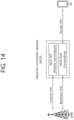
- FIG. 14 illustrates a link between a base station, an NCR, and a UE.
- An NCR-MT may be defined as a functional entity that communicates with a base station (gNB) via a control link (C-link) to enable information exchange (e.g., side control information).
- C-link may be based on the NR Uu interface.
- Side control information may be at least information for NCR-Fwd control.
- NCR-Fwd may be defined as a functional entity that amplifies and transfers UL/DL RF signals between a base station and a UE through a backhaul link and an access link. The operation of NCR-Fwd is controlled according to the side control information received from the base station.
- the contents of the present disclosure are described assuming an operation in NCR. However, the contents of the present disclosure may also be applied to non-NCR devices. For example, the contents of the present disclosure may be applied to the operation of RIS. To this end, the NCR mentioned in this disclosure may be replaced with RIS and expanded/interpreted.
- the RU plays a role in forwarding signals from the base station to the UE and forwarding signals from the UE to the base station in the RIS, and the MT may serve to receive side control information for controlling signal transmission of the RU from the base station.
- the present disclosure proposes an association between side control information and time domain resources during NCR operation.
- a network may be interpreted as being replaced with a base station or CU/DU.
- a base station may be interpreted as being replaced with a network, CU, or DU.
- the RF end adjusts the transmit/receive beam direction, DL/UL direction, ON/OFF status, transmit power, and the like.
- the operation of this RU cannot be determined by the NCR itself and can be completely controlled by the base station.
- the MT may receive information (i.e., side control information) necessary for controlling the operation of the RU from the base station. At least some or all of this side control information may be conveyed via L1/L2 signaling such as DCI (e.g., DCI format 2_8), MAC-CE.
- DCI e.g., DCI format 2_8
- MAC-CE MAC-CE
- the side control information may include, for example, all or part of the following information.
- Side control information may be applied differently for each time resource. In this case, it is necessary to indicate side control information for each time resource.
- side control information When side control information is assumed to be transmitted through MAC-CE and/or DCI, side control information may be transmitted through different MAC-CEs and/or DCIs for each time resource unit. In this case, there is a burden of transmitting side control information for each time resource unit. Considering this, when side control information is transmitted once, side control information for a plurality of time resource units may be indicated.
- NCR network-controlled repeater
- NCR-MT NCR-MT
- the procedures for NCR-MT to perform cell search, system information acquisition, random access procedure, UCI reporting, or PDCCH monitoring may be identical to those for the UE.
- the procedure for NCR-MT to perform PDSCH reception, CSI-RS measurement and CSI determination, PUSCH transmission or SRS transmission may also be identical to the corresponding procedure for the UE.
- NCR performs Tx/Rx beamforming to the backhaul link and/or Tx/Rx beamforming to the access link, and can (or assumes) perform beam adaptation to an appropriate beam direction among multiple beam directions.
- the beam direction applied when NCR-Fwd performs DL-Tx (downlink transmission) to the access link and/or the beam direction applied when UL-Rx (uplink reception) to the access link may be indicated by a base station (BS, gNB) or implicitly determined by a specific rule, etc.
- BS base station
- gNB base station
- the present disclosure proposes a method for determining the direction of the DL-Tx and/or the UL-Rx beam and whether to forward it, when the NCR-Fwd performs forwarding (i.e., DL-Tx) of a DL signal (of a base station) to a UE and/or reception (UL-Rx) of an UL signal from a UE over an access link for forwarding (to a base station). That is, it describes a method for determining the direction and whether to forward of a DL-Tx beam and/or a UL-Rx beam in an access link.
- NCR-Fwd In order for NCR-Fwd to determine the direction of the DL-Tx and/or UL-Rx beam to be applied for forwarding operation to the access link, information on the beam direction to be applied by NCR-Fwd can be configured/indicated from the base station to the NCR-MT.
- the NCR-MT of the NCR receives information about the beam direction of the access link, the NCR can determine the beam direction to be applied to the access link from this and perform a forwarding operation to the access link of the NCR-Fwd in the corresponding beam direction.
- This beam indication is associated with a specific time resource, allowing different (independent) beam directions to be applied depending on the time resource for forwarding operations to the access link of NCR-Fwd.
- a value corresponding to the beam direction of the access link of the NCR-Fwd may be indicated.
- a beam index or TCI state ID may be indicated for Tx beam indication of the access link of NCR-Fwd.
- both the beam index and the TCI state ID may be collectively referred to as the TCI state ID. That is, in the present disclosure, the TCI state ID for the access link of NCR-Fwd may mean the beam index for the access link of NCR-Fwd.
- NCR-Fwd can assume that the two transmissions of the access link at t1 and t2 are in a QCL relationship with each other. That is, NCR-Fwd should transmit so that the two transmissions of the access links at t1 and t2 have a QCL relationship with each other.
- being in a QCL relationship can include all or some of the following meanings.
- the TCI state ID used to indicate the beam direction of the access link of NCR-Fwd can be mapped to the transmission of a specific DL RS (downlink reference signal).
- a specific TCI state ID can be mapped to a specific DL RS ID.
- the following mapping relationship can be set from the base station to the NCR-MT.
- Method 1 DL RS ID(s) can be set, which are mapped to each TCI state ID.
- TCI state ID(s) mapped to DL RS ID can be set.
- multiple DL RS IDs may be mapped to the same TCI state ID. However, one DL RS ID may not be mapped to multiple TCI state IDs.
- the above DL RS ID may mean an SS/PBCH block index (SSB index) and/or a CSI-RS index.
- the SSB index and the CSI-RS index may mean the index of SSB and the index of CSI-RS configured to the NCR-MT from the base station.
- NCR-Fwd may assume that transmissions on an access link applying the TCI state ID and transmissions on an access link of a DL RS for the DL RS ID are in a QCL relationship with each other. That is, NCR-Fwd should be transmitted so that transmissions to the access link applying the corresponding TCI state ID and transmissions to the access link of the DL RS for the corresponding DL RS ID have a QCL relationship with each other.
- NCR-Fwd should transmit in such a way that transmissions to the access link at t1 have a QCL relationship with transmissions to the access link at the time resource where SSB index m is transmitted.
- TCI states for transmission to the access link of NCR-Fwd and an ID (TCI state ID) corresponding to each TCI state are set. These configurations may be set from the base station to the NCR-MT. For this purpose, the following configurations may be included specifically.
- the TCI states that are set for reception on the control link (C-link) of the NCR-MT may be reused for the TCI states for transmission on the access link of the NCR-Fwd.
- the TCI states set for the NCR-MT for DL-Rx from the base station may be applied for transmission on the access link of the NCR-Fwd.
- the NCR-MT may be configured with the TCI states, for example, as follows.
- a TCI state ID e.g., 'tci-StateId' in TCI-State IE
- a DL RS ID e.g., 'referenceSignal' in TCI-State IE
- the TCI state corresponding to the TCI state ID n may be set to the DL RS ID with the SSB index m.
- the NCR-Fwd may determine that a TCI state corresponding to TCI state ID n exists for the transmission to the access link and that the transmission to the access link with this TCI state should be transmitted such that the transmission to the access link with SSB index m has a Quasi Co Location (QCL) relationship with the transmission to the access link in the time resource from which the SSB index m is transmitted.
- QCL Quasi Co Location
- FIG. 15 shows an example of mapping between beam index/TCI state of NCR-Fwd and SSB.
- each TCI state may be mapped to a specific SSB index among the SSB indexes existing in the cell.
- Tx beams #0, #1, #2, and #3 of NCR are mapped to SSB#4, #5, #6, and #7, respectively.
- NCR-Fwd when NCR-Fwd is instructed to apply a Tx beam (TCI state) when performing transmission through an access link, NCR-Fwd may perform transmission in the direction of the applied Tx beam in the time resource for transmitting SSB for the SSB index mapped to the corresponding Tx beam (TCI state).
- NCR-Fwd performs transmission in the direction of Tx beams #0, #1, #2, #3 in the time resources where SSB#4, #5, #6, #7 are transmitted.
- NCR-Fwd does not perform forwarding in the time resources where SSB#0, #1, #2, #3 are transmitted.
- TCI states may be preset and only some of them may be used for actual beam direction.
- the TCI states set for the NCR-MT are reused for the TCI states for the transmission of the access link of the NCR-Fwd as in approach 2 above, only some of the TCI states set for the NCR-MT may be used as the TCI states for the actual transmission of the access link of the NCR-Fwd.
- TCI states for transmission on the access link of NCR-Fwd some TCI states are determined as valid TCI states, and a specific valid TCI state may be applied for transmission on the access link of NCR-Fwd at a specific time resource.
- NCR-Fwd may determine valid TCI states among the TCI states for transmission on the access link as follows.
- NCR-Fwd may be explicitly configured with TCI states that are valid TCI states among the TCI states configured for transmission on the access link.
- the TCI state for transmission on the access link may be set/determined as in Approach 1 and/or Approach 2.
- the configurations for these valid TCI states may be set to the NCR-MT from the base station through signaling such as RRC, MAC-CE, etc.
- DL RS may be mapped only to some TCI states.
- a TCI state in which a mapped DL RS ID exists may be determined as a valid TCI state.
- NCR-Fwd may perform DL RS forwarding only for some DL RS IDs. In this case, whether or not to perform NCR-Fwd forwarding may be set or determined for each DL RS ID. In this case, the NCR-Fwd may determine that the TCI state to which the DL RS ID that the NCR-Fwd performs forwarding is mapped is a valid TCI state, and the TCI state to which the DL RS ID that the NCR-Fwd does not perform forwarding is not a valid TCI state.
- NCR-MT may be configured with information about SSB (SS/PBCH block) (e.g., information about SSB symbol) from the base station. For example, this configuration may be set via ssb-PositionsInBurst in SIB1 or ssb-PositionsInBurst in ServingCellConfigCommon. Through this, the NCR-MT may determine the symbol resource (time resource) in which the SSB is transmitted per SSB index.
- SSB SS/PBCH block
- the NCR-MT may be configured with information about CSI-RS symbols from the base station. Through this, the NCR-MT may determine the symbol resources for which CSI-RS is transmitted per CSI-RS index. These CSI-RSs may be limited to periodic CSI-RSs or periodic NZP-CSI-RSs. These configurations may be set, for example, by 'NZP-CSI-RS-Resource'.
- the base station may transmit SSB transmissions for SSB indexes #0, #1, #2, and #3 in different beam directions for each index.
- NCR-MT may perform reception by applying different DL Rx beams to receive SSB for SSB indexes #0, #1, #2, and #3.
- the base station may transmit a DL signal for that NCR-MT in the beam direction that transmitted the SSB with the good measurement result.
- the base station may perform downlink transmission to NCR-MT in the beam direction used when transmitting SSB index #3. And, to receive this, NCR-MT may perform downlink reception using the best DL Rx beam when receiving SSB index #3.
- NCR-Fwd may receive SSB for SSB index #4, #5, #6, and #7 from the base station and transmit the SSB through the access link in different Tx beam directions according to the index.
- the base station may transmit SSB for SSB index #4, #5, #6, #7 in the beam direction that NCR-MT can best receive. If the NCR-MT reports SSB index #3 as having the best measurement result among SSB indexes #0, #1, #2, and #3, the base station may apply the Tx beam direction applied when transmitting SSB index #3 to perform SSB transmission for SSB indexes #4, #5, #6, and #7.
- the NCR may not forward all SSB transmissions.
- the NCR may forward only some SSB transmissions and not forward some SSB transmissions.
- the base station transmits SSBs for SSB indexes #0, #1, ... #7, but NCR-Fwd may perform forwarding only in the time resources in which SSBs for SSB indexes #4, #5, #6, and #7 are transmitted.
- the UE can determine the strength/quality of the received signal for a signal transmitted directly from the base station through SSB indexes #0, #1, #2, #3, and can determine the strength/quality of the received signal for a signal forwarded and transmitted from the NCR through SSB indexes #4, #5, #6, #7.
- Method 1 Method of transmitting using the TCI state to which the SSB index is mapped.
- DL RS ID (e.g., SSB index) may be mapped to each TCI state set for transmission on the access link of NCR-Fwd.
- SSB index #m may be mapped to TCI state ID #n.
- NCR-Fwd may perform transmission on the access link by aligning with (using) the TCI state corresponding to TCI state #n in the time resource where SSB for SSB index #m is transmitted.
- the time resource through which SSB is transmitted may mean the symbol resource through which SSB is transmitted. That is, NCR-Fwd may perform transmission on an access link in accordance with the TCI state corresponding to TCI state ID #n in the symbol resource where SSB for SSB index #m is transmitted.
- the time resource in which SSB is transmitted may mean a slot resource that includes a symbol resource in which SSB is transmitted. That is, NCR-Fwd may perform transmission on an access link in accordance with the TCI state corresponding to TCI state ID #n in a slot resource containing a symbol resource where SSB for SSB index #m is transmitted.
- Method 2 A method for indicating a beam direction per SSB index.
- NCR may be configured with information about beam direction in access link applied by SSB index transmitted from cell. This configuration information may be configured to the NCR-MT from base station through signaling such as RRC/MAC-CE.
- information about the beam index applied to each SSB index may be indicated.
- NCR-Fwd may perform transmission on the access link in accordance with beam index #n in the time resource in which SSB for SSB index #m is transmitted.
- the time resource through which SSB is transmitted may mean the symbol resource through which SSB is transmitted. That is, NCR-Fwd may perform transmission on an access link in accordance with beam index #n in symbol resources where SSB for SSB index #m is transmitted.
- the time resource in which SSB is transmitted may mean a slot resource that includes a symbol resource in which SSB is transmitted. That is, NCR-Fwd may perform transmission on an access link in accordance with beam index #n in slot resources that include symbol resources where SSB for SSB index #m is transmitted.
- NCR-Fwd may determine whether forwarding operation is performed per SSB index as follows.
- NCR-MT is configured with information, from the base station, on whether to forward per SSB index.
- the NCR-MT when configured with information about the SSB transmission resources in a cell (e.g., ssb-PositionsInBurst), it may be configured with information about whether to forward together. Alternatively, the information about whether to forward may be set independently for each SSB index.
- NCR-MT when NCR-MT is configured with information about SSB transmission resources in a cell (e.g., ssb-PositionsInBurst), it is configured together with information about whether the corresponding SSB/CSI-RS is set for NCR-MT operation or NCR-Fwd operation. Or, independently, it is set for each SSB index whether the corresponding SSB is set for NCR-MT operation or NCR-Fwd operation.
- NCR-Fwd determines the corresponding SSB/CSI-RS index to be the SSB/CSI-RS index performing the forwarding.
- NCR-Fwd determines that SSB/CSI-RS index to be an SSB/CSI-RS index that does not perform forwarding.
- NCR-Fwd determines that SSB/CSI-RS index to be the SSB/CSI-RS index that performs the forwarding.
- the NCR-MT is configured with information, from the base station, about the SSB/CSI-RS indexes that perform forwarding.
- NCR-MT is configured with a list of SSB indexes that perform (or do not perform) forwarding.
- NCR-MT is set with a list of SSB indexes for the operation of NCR-MT and/or a list of SSB indexes for the operation of NCR-Fwd.
- NCR-Fwd determines the SSB index as the SSB index performing forwarding.
- NCR-Fwd determines the SSB index as an SSB index that does not perform forwarding.
- NCR-Fwd determines the SSB index as the SSB index to perform forwarding.
- Method 3 Determine whether to forward based on whether the SSB index is mapped to the TCI status.
- DL RS ID (e.g., SSB index) may be mapped to each TCI state set for transmission on the access link of NCR-Fwd. If a specific SSB index is mapped to a specific TCI state, NCR-Fwd considers the SSB index as an SSB index that performs forwarding. Otherwise, it considers the SSB index as an SSB index that does not perform forwarding.
- the SSB index mapped to the valid TCI state is determined as the SSB index that performs forwarding.
- the SSB index that is not mapped to the valid TCI state is determined as the SSB index that does not perform forwarding.
- the SSB index indicated with information about the beam index is determined as the SSB index that performs forwarding.
- the SSB index for which the beam index is not indicated is determined as the SSB index that does not perform forwarding.
- NCR-Fwd performs forwarding in the time resources where the SSB corresponding to the SSB index determined to perform forwarding is transmitted. Additionally, NCR-Fwd does not perform forwarding in the time resources where the SSB corresponding to the SSB index determined not to perform forwarding is transmitted.
- the time resource in which SSB is transmitted may mean the OFDM symbol(s) resource in which SSB is transmitted. That is, NCR-Fwd performs forwarding in the symbol(s) resource in which SSB corresponding to the SSB index determined to perform forwarding is transmitted. Additionally, NCR-Fwd may not perform forwarding on symbol(s) resources where SSBs corresponding to SSB indexes that are determined not to perform forwarding are transmitted.
- the time resource in which SSB is transmitted may mean the slot(s) resource including the OFDM symbol(s) resource in which SSB is transmitted. That is, NCR-Fwd performs forwarding in the slot(s) resource including the symbol(s) resource in which SSB corresponding to the SSB index determined to perform forwarding is transmitted. Additionally, NCR-Fwd may not perform forwarding in slot(s) resources that contain symbol(s) resources in which SSB corresponding to SSB index that is determined not to perform forwarding are transmitted. If a slot contains both symbols for SSBs that perform forwarding and symbols for SSBs that do not perform forwarding, NCR-Fwd may perform forwarding in that slot.
- FIG. 16 illustrates a method of operation of a device in a wireless communication system.
- the device performs an initial access procedure with a network (e.g., a base station) (S161).
- the initial access procedure may be, for example, at least some of the procedures described in FIG. 10 .
- the device receives SSB (synchronization signal/physical broadcast channel block) configuration information from the network (S162).
- SSB synchronization signal/physical broadcast channel block
- the device performs a forwarding operation based on the SSB configuration information, wherein the device performs the forwarding operation only in a time resource in which an SSB corresponding to a specific SSB index among the SSB indexes informed by the SSB configuration information is transmitted (S163).
- the above device may be an NCR.
- the NCR includes an NCR (network-controlled repeater)-MT (mobile termination) entity and an NCR-Fwd (Forwarding) entity.
- the NCR-Fwd may transmit or receive only after the NCR-MT receives on the control link an indication for one or more beams for the NCR-Fwd to use for transmissions or receptions over corresponding one or more time resources on the access link.
- the NCR-Fwd does not transmit or receive until the link recovery procedure is complete.
- NCR may receive TDD UL-DL configuration (e.g., 'tdd-UL-DL-ConfigurationCommon' and/or 'tdd-UL-DL-ConfigurationDedicated') from the network via NCR-MT.
- TDD UL-DL configuration e.g., 'tdd-UL-DL-ConfigurationCommon' and/or 'tdd-UL-DL-ConfigurationDedicated'
- the NCR-Fwd i) receives on the backhaul link or ii) transmits on the access link only in symbols indicated as downlink by TDD UL-DL configuration.
- the NCR-Fwd i) receives on the access link or ii) transmits on the backhaul link only in symbols indicated as uplink by TDD UL-DL configuration.
- a TCI state for receptions on the backhaul link is same as a TCI state for receptions on the control link in the set of symbols.
- a spatial filter for transmissions on the backhaul link is same as a spatial filter for transmissions on the control link in the set of symbols.
- the NCR When the NCR does not simultaneously receive on the control link and the backhaul link, it may behave as follows.
- the NCR When the NCR does not simultaneously transmit on the control link and the backhaul link, it may behave as follows.
- the NCR-Fwd uses a same beam for transmissions and receptions on the access link during respective time resources associated with the beam.
- the NCR may be provided a list of sets of resources for transmissions or receptions on the access link.
- a set of resources, from the list of sets of resources, is provided by periodic forwarding resource set and occurs with a specific periodicity.
- a resource from the set of resources is provided by a pair of i) a time resource and ii) a beam with an index.
- the time resource starts at a slot that is offset by indicated slots from the start of the period for the set of resources and at a symbol that is offset by indicated symbols from the start of the slot, and has an indicated/configured duration for an indicated SCS.
- the NCR may be provided with a list of resource sets for transmission or reception on an access link by an RRC message, and the MAC CE command may indicate a resource set among the resource sets in the list that the NCR will use or stop using.
- the NCR-MT may be configured to monitor PDCCH according to USS sets for detection of a DCI format 2_8 with CRC scrambled by an NCR-RNTI.
- a time resource and a corresponding beam index for transmissions or receptions on the access link are indicated by corresponding fields in DCI format 2_8.
- DCI format 2_8 is a DCI format which is used for notifying the aperiodic beam indication and associated time resources, and is a DCI format with a CRC scrambled by NCR-RNTI.
- DCI format 2_8 may include N beam indexes and N time resource indications.
- the N beam indexes are sequentially associated with the N time resource indications in a one-to-one mapping.
- N is configured by a higher layer parameter.
- the size of DCI format 2_8 may be up to 128 bits.
- the NCR uses for the set of symbols a beam index that is indicated by a DCI format 2_8 that the NCR-MT detects in a most recent PDCCH monitoring.
- a first time resource included in a semi persistent forwarding resource set is indicated by a MAC CE command and is associated with a first beam index
- a second time resource included in a periodic forwarding resource set is provided and is associated with a second beam index
- the first time resource overlaps with the second time resource in a set of symbols
- the NCR applies the first beam index for transmissions or receptions on the access link in the set of symbols.
- the NCR applies, for transmissions or receptions on the access link in the set of symbols, i) the first beam index, if the periodic forwarding resource set or the persistent forwarding resource set includes a priority flag (priorityFlag), and ii) the second beam index, if the periodic forwarding resource set or the persistent forwarding resource set does not include a priority flag (priorityFlag).
- the NCR does not expect overlapping time resources provided by either the periodic forwarding resource set or the persistent forwarding resource set to be associated with different beam indexes.
- a transmission configuration indicator (TCI) state may be configured for transmission on an access link of NCR-Fwd.
- NCR-Fwd may determine that an SSB index mapped to the TCI state is an SSB index that performs a forwarding operation.
- NCR-Fwd may determine that an SSB index not mapped to the TCI state is an SSB index that does not perform a forwarding operation.
- the SSB configuration information may include a list of SSB indexes for which the device performs forwarding operations.
- the specific SSB index may be an SSB index included in the list.
- the TCI state may be a valid TCI state.
- the NCR-Fwd may determine that the SSB index to which the beam index applied by the NCR-Fwd is indicated is the SSB index to which the forwarding operation is performed among the SSB indexes informed by the above SSB configuration information.
- the NCR-Fwd may determine that the SSB index to which the beam index applied by the NCR-Fwd is not indicated is an SSB index to which the NCR-Fwd does not perform a forwarding operation among the SSB indexes informed by the above SSB configuration information,
- the NCR-MT may receive a first list of first SSB indexes for operation of the NCR-MT and a second list of second SSB indexes for operation of the NCR-Fwd.
- NCR-Fwd may determine that each SSB index included in the second list is an SSB index that performs a forwarding operation.
- NCR-Fwd may determine that each SSB index included in the first list is an SSB index that does not perform a forwarding operation.
- NCR-Fwd may determine that the SSB index included in both the first list and the second list is an SSB index that performs the forwarding operation of the NCR-Fwd.
- the SSB configuration information may inform a beam ID (identity) or TCI state associated with each SSB index.
- NCR-Fwd may perform a forwarding operation of an access link by using a beam determined based on the beam ID or TCI state associated with the specific SSB index in a time resource in which an SSB having the specific SSB index is transmitted.
- the UE can directly receive and measure essential signals transmitted by the base station as needed.
- the signaling overhead in controlling the forwarding operation of the NCR can be reduced.
- FIG. 17 illustrates the forwarding operation method of NCR.
- a TCI state may be set for transmission on an access link of NCR-Fwd.
- TCI state #1 may be set for time resource #2 of an access link
- TCI state #2 may be set for time resource #4
- TCI state #3 may be set for time resource #7.
- a DL RS ID e.g., SSB index
- SSB index #2 is mapped to TCI state #1
- SSB index #1 is mapped to TCI state #2
- SSB index #3 is mapped to TCI state #3.
- NCR-Fwd determines the SSB index as an SSB index that performs forwarding. Otherwise, that is, if the SSB index is not mapped to a TCI state, it determines the SSB index as an SSB index that does not perform forwarding.
- SSB index #2 mapped to TCI state #1 is determined to be an SSB index that performs forwarding, and other SSB indexes are determined to be SSB indexes that do not perform forwarding.
- time resource #4 of the access link SSB index #1 mapped to TCI state #2 is determined to be an SSB index that performs forwarding, and other SSB indexes are determined to be SSB indexes that do not perform forwarding.
- time resource #7 of the access link SSB index #3 mapped to TCI state #3 is determined to be an SSB index that performs forwarding, and other SSB indexes are determined to be SSB indexes that do not perform forwarding.
- NCR specifically, NCR-Fwd
- an SSB index mapped to the valid TCI state may be determined as an SSB index that performs forwarding.
- An SSB index that is not mapped to a valid TCI state is determined as an SSB index that does not perform forwarding.
- an SSB index indicated with information about the beam index is determined as an SSB index that performs forwarding.
- An SSB index for which a beam index is not indicated is determined as an SSB index that does not perform forwarding.
- NCR-Fwd performs forwarding in the time resources where an SSB corresponding to an SSB index determined to perform forwarding is transmitted. NCR-Fwd does not perform forwarding in the time resources where an SSB corresponding to an SSB index determined not to perform forwarding is transmitted.
- FIG. 18 illustrates an operation method of a base station in a wireless communication system.
- the base station performs an initial access procedure with the NCR through the NCR-MT of the NCR, which includes NCR (network-controlled repeater)-MT (mobile termination) and NCR-Fwd (Forwarding) (S181).
- the initial access procedure may be, for example, by at least some of the procedures described in FIG. 10 .
- the base station transmits SSB (synchronization signal/physical broadcast channel block) configuration information to the NCR-MT (S182).
- SSB synchronization signal/physical broadcast channel block
- the base station controls the forwarding operation of the NCR-Fwd based on the SSB configuration information, and controls the NCR-Fwd to perform the forwarding operation only in time resources in which an SSB corresponding to a specific SSB index among the SSB indexes indicated by the SSB configuration information is transmitted (S183).
- NCR performs Tx/Rx beamforming to the backhaul link and/or Tx/Rx beamforming on the access link, and can (or assumes) perform beam adaptation to an appropriate beam direction among multiple beam directions.
- the beam direction applied when NCR-Fwd performs DL-Tx (downlink transmission) on the access link and/or the beam direction applied when performing UL-Rx (uplink reception) on the access link may be indicated by the base station or implicitly determined by a specific rule.
- the beam direction applied when NCR-Fwd performs DL-Rx (downlink reception) to the backhaul link and/or the beam direction applied when performing UL-Tx (uplink transmission) to the backhaul link may be determined as follows.
- the TCI state applied by NCR-MT for the control link (C-link) at that time resource is applied as is for the operation of NCR-Fwd to the backhaul link. That is, the beam direction applied by NCR-MT for the control link is applied as is to the backhaul link of NCR-Fwd.
- NCR-Fwd When NCR-Fwd performs DL-Rx and/or UL-Tx to the backhaul link at a specific time resource, among the TCI states set by the base station for the NCR-MT operation to the control link, a specific TCI state is applied for operation of NCR-Fwd to the backhaul link.
- the TCI state that NCR-Fwd applies for operation to the backhaul link may be explicitly instructed by the base station or implicitly determined by certain conditions/rules, etc.
- the NCR-MT may be configured with information about the SSB (SS/PBCH block) symbols from the base station. Specifically, these configuration may be set via 'ssb-PositionsInBurst' in SIB1 or 'ssb-PositionsInBurst' in ServingCellConfigCommon. Through this, the NCR-MT may determine the symbol resource from which an SSB is transmitted per SSB index. In addition, the NCR-MT may be configured with information about CSI-RS symbols from the base station. Through this, the NCR-MT may determine the symbol resources on which CSI-RS is transmitted per CSI-RS index. These CSI-RS may be limited to periodic CSI-RS or periodic NZP-CSI-RS. Specifically, these configurations may be set by 'NZP-CSI-RS-Resource'.
- This disclosure describes the forwarding behaviour of SSB in NCR-Fwd for ease of description, but the contents of this disclosure can also be applied to the forwarding behaviour of CSI-RS in NCR-Fwd, i.e., the following disclosure can be interpreted by replacing SSB with CSI-RS.
- the NCR may not forward all SSB transmissions. In order to perform measurements independently for transmissions on the base station's direct link and for forwarded links forwarded by the NCR, the NCR may forward only some SSB transmissions and not others.
- the base station transmits SSBs for SSB indexes #0, #1, ..., and #7, but the NCR-Fwd may only perform forwarding in the time resources where SSBs for SSB indexes #4, #5, #6, and #7 are transmitted.
- SSB indexes #4, #5, #6, and #7 are transmitted for measurement of signals forwarded by the NCR, so the NCR-MT does not receive those SSBs and may only perform measurements via SSB indexes #0, #1, #2, and #3.
- the TCI states applied by the NCR-MT to transmit and receive from the base station have one of SSB index #0, #1, #2, #3 as the source DL RS, and depending on the TCI state applied, DL Rx may be performed using one of the appropriate DL Rx beams to receive SSB index #0, #1, #2, #3.
- the source DL RS for a specific TCI state is the DL RS ID that is in a QCL relationship with the transmission for the TCI state, e.g. the 'referenceSignal' in the TCI-State IE.
- the NCR-Fwd may not perform forwarding for SSB indexes #0, #1, #2, and #3, and perform forwarding only for SSB indexes #4, #5, #6, and #7.
- the NCR-Fwd may perform DL Rx using the beam directions that the NCR-MT applies for the control link, i.e., it may perform DL Rx from the backhaul link by applying one of the TCI states set for the NCR-MT.
- NCR-MT may determine the appropriate DL Rx beam to apply to receive SSB indexes #0, #1, #2, #3. However, since NCR-MT does not perform measurements for SSB indexes #4, #5, #6, #7, NCR-MT cannot determine the appropriate DL Rx beam to apply to receive SSB indexes #4, #5, #6, #7.
- the base station may transmit SSB transmissions for SSB indexes #0, #1, #2, and #3 in different beam directions for each index.
- NCR-MT may perform reception by applying different DL Rx beams to receive SSB for SSB indexes #0, #1, #2, and #3.
- NCR-MT may receive SSB for SSB index #0, #1, #2, #3 and report good SSB index(es) and measurement value(s) for measurement (e.g., L1-RSRP (Reference Signals Received Power)). Then, the base station may transmit the DL signal for the NCR-MT in the beam direction in which the SSB with good measurement results was transmitted.
- L1-RSRP Reference Signals Received Power
- the base station may perform downlink transmission to NCR-MT in the beam direction used when transmitting SSB index #3. And, to receive it, NCR-MT may perform downlink reception using the DL Rx beam that was the best when receiving SSB index #3.
- the NCR-Fwd may receive SSBs for SSB indexes #4, #5, #6, and #7 from the base station and transmit the SSBs over the access link in different Tx beam directions according to the SSB index.
- the base station may transmit SSB for SSB indexes #4, #5, #6, and #7 in the beam direction that is best received by the NCR-MT. If the NCR-MT reports SSB index #3 as having the best measurement result among SSB indexes #0, #1, #2, and #3, the base station may apply the Tx beam direction applied when transmitting SSB index #3 to perform SSB transmission for SSB indexes #4, #5, #6, and #7.
- NCR-Fwd it is desirable for NCR-Fwd to receive SSBs for SSB indexes #4, #5, #6, and #7 by applying the Rx beam that NCR-MT applied to receive SSBs for SSB index #3.
- NCR-MT may be configured with the TCI status applied by NCR-Fwd in the transmission time resource of SSB from the base station.
- the SSB may mean an SSB corresponding to an SSB index for which NCR-Fwd performs forwarding. That is, when there are multiple SSB indexes and NCR-Fwd performs forwarding operation for some SSB indexes, it may mean a transmission time resource of an SSB for an SSB index for which NCR-Fwd performs forwarding.
- independent TCI states can be set for each SSB index.
- the TCI state may be applied only to some SSB indexes.
- a list of SSB indexes to which the TCI state is applied may be set.
- This information can be set, for example, via RRC or MAC-CE.
- NCR-Fwd may apply the 'DL-Rx beam corresponding to the set TCI state' to perform reception to the backhaul link in the 'time resource where SSB is transmitted'.
- SSB may mean an SSB corresponding to an SSB index on which NCR-Fwd performs forwarding. That is, when there are multiple SSB indexes and NCR-Fwd performs forwarding operation for some SSB indexes, it may mean the transmission time resource of SSB for the SSB index for which NCR-Fwd performs forwarding.
- the 'time resource during which SSB is transmitted' may specifically mean the following.
- the DL-Rx beam of NCR-Fwd may be different depending on the symbol resource within the same slot.
- the DL-Rx beam may be determined on a slot-by-slot basis.
- the term 'DL-Rx beam corresponding to the TCI state' may specifically mean the following.
- the TCI states applied to determine the DL-Rx beam may differ for each time resource corresponding to the SSB index.
- the TCI state set for SSB index #n is used to determine the DL-Rx beam to apply.
- NCR-Fwd may determine that an SSB index for which a TCI state is not set or to which the set TCI state is not applied is an SSB index for which forwarding is not performed. And/or, for an SSB index for which a TCI state is set or to which the set TCI state is applied, NCR-Fwd may determine that the SSB index is an SSB index for which forwarding is performed. In this case, NCR-Fwd performs forwarding in the time resource in which the SSB corresponding to the SSB index determined to perform forwarding is transmitted. Additionally, NCR-Fwd may not perform forwarding in the time resource in which the SSB corresponding to the SSB index determined not to perform forwarding is transmitted.
- NCR-MT may be configured with the SSB index (source SSB index) that becomes the source of the TCI applied by NCR-Fwd in the transmission time resource of SSB, from the base station.
- the above SSB may mean an SSB corresponding to an SSB index for which NCR-Fwd performs forwarding. That is, when there are multiple SSB indexes and NCR-Fwd performs forwarding operation for some SSB indexes, it may mean a transmission time resource of an SSB for an SSB index for which NCR-Fwd performs forwarding.
- an independent source SSB index may be set for each SSB index.
- the source SSB index may be set only for some SSB indexes.
- the source SSB index is not set for a specific SSB index, it can be assumed that the SSB index and the source SSB index are identical.
- the source SSB index may be applied only to some SSB indexes.
- a list of SSB indexes to which the source SSB index is applied may be set.
- This information may be set, for example, via RRC or MAC-CE.
- NCR-Fwd may apply the configured 'DL-Rx beam corresponding to the source SSB index' to perform reception to the backhaul link in the 'time resource where SSB is transmitted'.
- SSB may mean an SSB corresponding to an SSB index on which NCR-Fwd performs forwarding. That is, when there are multiple SSB indexes and NCR-Fwd performs forwarding operation for some SSB indexes, it may mean the transmission time resource of SSB for the SSB index for which NCR-Fwd performs forwarding.
- the 'time resource during which SSB is transmitted' may specifically mean the following.
- i) It may mean the symbol(s) through which SSB is transmitted.
- the DL-Rx beam of NCR-Fwd may be different depending on the symbol resource within the same slot.
- DL-Rx beam may be determined on a slot basis.
- 'DL-Rx beam corresponding to source SSB index' may specifically mean the following.
- the source SSB index applied to determine the DL-Rx beam for each time resource corresponding to the SSB index may be different.
- the time resource from which the SSB for SSB index #n is transmitted uses the source SSB index set for SSB index #n to determine which DL-Rx beam to apply.
- NCR-Fwd may determine that an SSB index for which no source SSB index is set or for which the source SSB index set is not applied is an SSB index for which forwarding is not performed. And/or the source SSB index is set, or for an SSB index to which the set source SSB index applies, the NCR-Fwd may determine that it is the SSB index for which it is performing forwarding. In this case, the NCR-Fwd performs the forwarding on the time resource on which the SSB corresponding to the SSB index determined to be performing the forwarding is transmitted. Additionally, the NCR-Fwd may not perform forwarding on the time resource on which the SSB corresponding to the SSB index determined not to be performing forwarding is transmitted.
- NCR-Fwd determines the direction of the UL-Tx beam on the physical random access channel (PRACH) resource when forwarding to the backhaul link.
- PRACH physical random access channel
- PRACH slots which are slot resources that can transmit PRACH
- PRACH occasions which may be abbreviated as ROs
- a UE may transmit PRACH through a specific RO.
- Each RO is associated with a specific SSB index.
- An RO is associated with one SSB index, and multiple ROs can be associated with the same SSB index.
- a UE When a UE determines that the reception quality (e.g., RSRP) of a specific SSB is good and sends a PRACH to that cell, it may send the PRACH through the RO(s) associated with the received SSB index.
- the reception quality e.g., RSRP
- the UL Tx beam applied by NCR-Fwd may vary depending on the SSB index associated with that RO. This is because the DL Tx beam direction of the base station may change depending on the SSB index, and accordingly, the UL Tx beam direction appropriate for transmitting PRACH may change.
- NCR-Fwd may perform UL transmission by applying UL Tx beams in each time resource as instructed by the base station without knowing information about PRACH transmission resources. However, in this case, there may be a burden of signaling overhead as it should receive instructions from the base station each time about the beam that NCR-Fwd should apply.
- NCR-Fwd determines the UL Tx beam applied in the PRACH transmission resource and applies the beam in the corresponding resource, the burden of having to receive beam instructions from the base station every time can be reduced.
- NCR-MT since NCR-MT receives system information from the base station, NCR-Fwd can also know information about PRACH transmission resources. Using the information about these PRACH transmission resources and the information about the associated SSB index in each RO, NCR-Fwd can determine the UL Tx beam to the backhaul link in the PRACH transmission resources as follows.
- NCR-Fwd can determine the UL Tx beam to the backhaul link in the time resource where a specific RO exists as follows.
- the beam direction applied by NCR-Fwd for DL Rx in the time resource where the SSB corresponding to that SSB index is transmitted may be determined as the UL Tx beam in the time resource where that RO exists.
- the NCR-Fwd may determine and apply that the beam direction applied for UL Tx in the time resource where a specific RO is present is the same as the beam direction applied for DL Rx in the time resource that receives the SSB associated with that RO.
- the time resource in which the RO exists may mean the symbol(s) in which the RO exists. This requires that there are no different ROs associated with different SSB indexes on the same symbol resource.
- the time resource in which the RO exists can refer to the slot in which the RO exists. This requires that there are no different ROs associated with different SSB indexes on the same slot resource.
- NCR-Fwd may perform UL transmission in the time resource where a specific RO is present by applying the UL Tx beam direction associated with that RO.
- the NCR-MT may be configured by the base station with information about the beam direction that the NCR-Fwd applies for UL Tx in the time resource in which a specific RO is present. More specifically, the NCR-MT may be configured from the base station, for each RO, with information about the UL Tx beam associated with that RO.
- the time resource in which the RO exists may mean the symbol(s) in which the RO exists. This requires that there are no different ROs associated with different SSB indexes on the same symbol resource.
- the time resource in which the RO exists may refer to the slot in which the RO exists. This requires that there are no different ROs associated with different SSB indexes on the same slot resource.
- NCR-Fwd may perform UL transmission by applying the UL Tx beam direction linked to the SSB index associated with a specific RO in the time resource in which that RO exists.
- information about the UL Tx beam direction that is linked to a specific SSB index may be configured from the base station. More specifically, the NCR-MT may be configured with, from the base station, for each SSB index, information about the UL Tx beam linked to that SSB.
- NCR-Fwd will perform UL transmission by applying the same UL Tx beam direction (the UL Tx beam direction linked to the corresponding SSB index) in time resources where ROs associated with the same SSB index exist.
- the time resource in which the RO exists may mean the symbol(s) in which the RO exists. This requires that there are no different ROs associated with different SSB indexes on the same symbol resource.
- the time resource in which the RO exists may refer to the slot in which the RO exists. This requires that there are no different ROs associated with different SSB indexes on the same slot resource.
- the information about the UL Tx beam may be specifically as follows.
- the DL TCI state ID may be used to indicate the UL Tx beam direction for the backhaul link of NCR-Fwd. That is, the UL Tx beam direction applied by NCR-Fwd can be indicated by indicating the TCI state ID.
- the TCI state ID means the ID for the TCI state configured to NCR-MT for transmission and reception operations to the control link of NCR-MT.
- Beam correspondence may be assumed between DL reception and UL transmission on the backhaul link of NCR-Fwd.
- the UL-Tx beam of NCR-Fwd may be indicated by indicating the DL-Rx beam of NCR-Fwd. If a specific DL-Rx beam is indicated to inform the UL-Tx beam of the NCR-Fwd, it may mean that UL-Tx is performed using the same beam as that DL-Rx beam.
- the SSB index and/or the CSI-RS index may be used. That is, by indicating the SSB index and/or the CSI-RS index, the UL Tx beam direction applied by NCR-Fwd can be indicated.
- FIG. 19 illustrates a wireless device applicable to this specification.
- the first wireless device 100 and the second wireless device 200 may transmit/receive wireless signals through various wireless access technologies (e.g., LTE, NR).
- various wireless access technologies e.g., LTE, NR.
- the first wireless device 100 includes at least one processor 102 and at least one memory 104 and may further include at least one transceiver 106 and/or at least one antenna 108.
- the processor 102 may be configured to control the memory 104 and/or the transceiver 106 and to implement the descriptions, functions, procedures, proposals, methods, and/or operational flowcharts disclosed herein.
- the processor 102 may process information in the memory 104 to generate first information/signal and may then transmit a radio signal including the first information/signal through the transceiver 106.
- the processor 102 may receive a radio signal including second information/signal through the transceiver 106 and may store information obtained from signal processing of the second information/signal in the memory 104.
- the memory 104 may be connected to the processor 102 and may store various pieces of information related to the operation of the processor 102.
- the memory 104 may store a software code including instructions to perform some or all of processes controlled by the processor 102 or to perform the descriptions, functions, procedures, proposals, methods, and/or operational flowcharts disclosed herein.
- the processor 102 and the memory 104 may be part of a communication modem/circuit/chip designed to implement a radio communication technology (e.g., LTE or NR).
- the transceiver 106 may be connected with the processor 102 and may transmit and/or receive a radio signal via the at least one antennas 108.
- the transceiver 106 may include a transmitter and/or a receiver.
- the transceiver 106 may be replaced with a radio frequency (RF) unit.
- RF radio frequency
- the wireless device may refer to a communication modem/circuit/chip.
- the processor 102 may be included in an NCR including a network-controlled repeater (NCR)-mobile termination (MT) and an NCR-Forwarding (Fwd).
- the processor 102 performs an initial access procedure with a network, receives synchronization signal/physical broadcast channel block (SSB) configuration information from the network and performs a forwarding operation based on the SSB configuration information.
- SSB synchronization signal/physical broadcast channel block
- the processor performs the forwarding operation only in a time resource in which an SSB related to a specific SSB index among SSB indexes informed by the SSB configuration information is transmitted.
- the second wireless device 200 includes at least one processor 202 and at least one memory 204 and may further include at least one transceiver 206 and/or at least one antenna 208.
- the processor 202 may be configured to control the memory 204 and/or the transceiver 206 and to implement the descriptions, functions, procedures, proposals, methods, and/or operational flowcharts disclosed herein.
- the processor 202 may process information in the memory 204 to generate third information/signal and may then transmit a radio signal including the third information/signal through the transceiver 206.
- the processor 202 may receive a radio signal including fourth information/signal through the transceiver 206 and may store information obtained from signal processing of the fourth information/signal in the memory 204.
- the memory 204 may be connected to the processor 202 and may store various pieces of information related to the operation of the processor 202.
- the memory 204 may store a software code including instructions to perform some or all of processes controlled by the processor 202 or to perform the descriptions, functions, procedures, proposals, methods, and/or operational flowcharts disclosed herein.
- the processor 202 and the memory 204 may be part of a communication modem/circuit/chip designed to implement a radio communication technology (e.g., LTE or NR).
- the transceiver 206 may be connected with the processor 202 and may transmit and/or receive a radio signal via the at least one antennas 208.
- the transceiver 206 may include a transmitter and/or a receiver.
- the transceiver 206 may be replaced with an RF unit.
- the wireless device may refer to a communication modem/circuit/chip.
- Processor 202 may be included in a base station.
- the processor 202 performs an initial access procedure with a network-controlled repeater (NCR) including NCR-mobile termination (MT) and NCR-Forwarding (Fwd) through the NCR-MT, transmits synchronization signal/physical broadcast channel block (SSB) configuration information to the NCR-MT and controls a forwarding operation of the NCR-Fwd based on the SSB configuration information.
- NCR network-controlled repeater
- MT NCR-mobile termination
- Fwd NCR-Forwarding
- SSB synchronization signal/physical broadcast channel block
- the processor controls the NCR-Fwd to perform the forwarding operation only in a time resource in which an SSB related to a specific SSB index among SSB indexes informed by the SSB configuration information is transmitted.
- At least one protocol layer may be implemented, but limited to, by the at least one processor 102 and 202.
- the at least one processor 102 and 202 may implement at least one layer (e.g., a functional layer, such as PHY, MAC, RLC, PDCP, RRC, and SDAP layers).
- the at least one processor 102 and 202 may generate at least one protocol data unit (PDU) and/or at least one service data unit (SDU) according to the descriptions, functions, procedures, proposals, methods, and/or operational flowcharts disclosed herein.
- PDU protocol data unit
- SDU service data unit
- the at least one processor 102 and 202 may generate a message, control information, data, or information according to the descriptions, functions, procedures, proposals, methods, and/or operational flowcharts disclosed herein.
- the at least one processor 102 and 202 may generate a signal (e.g., a baseband signal) including a PDU, an SDU, a message, control information, data, or information according to the functions, procedures, proposals, and/or methods disclosed herein and may provide the signal to the at least one transceiver 106 and 206.
- a signal e.g., a baseband signal
- the at least one processor 102 and 202 may receive a signal (e.g., a baseband signal) from the at least one transceiver 106 and 206 and may obtain a PDU, an SDU, a message, control information, data, or information according to the descriptions, functions, procedures, proposals, methods, and/or operational flowcharts disclosed herein.
- a signal e.g., a baseband signal
- the at least one processor 102 and 202 may be referred to as a controller, a microcontroller, a microprocessor, or a microcomputer.
- the at least one processor 102 and 202 may be implemented by hardware, firmware, software, or a combination thereof.
- ASIC application-specific integrated circuit
- DSP digital signal processor
- DSPD digital signal processing devices
- PLD programmable logic devices
- FPGA field programmable gate array
- the one or more processors 102 and 202 may be implemented as at least one computer readable medium (CRM) including instructions based on being executed by the at least one processor.
- CRM computer readable medium
- CRM performs steps comprising: performing an initial access procedure with a network, receiving synchronization signal/physical broadcast channel block (SSB) configuration information from the network and performing a forwarding operation based on the SSB configuration information.
- SSB synchronization signal/physical broadcast channel block
- the processor performs the forwarding operation only in a time resource in which an SSB related to a specific SSB index among SSB indexes informed by the SSB configuration information is transmitted.
- the descriptions, functions, procedures, proposals, methods, and/or operational flowcharts disclosed herein may be implemented using firmware or software, and the firmware or software may be configured to include modules, procedures, functions, and the like.
- the firmware or software configured to perform the descriptions, functions, procedures, proposals, methods, and/or operational flowcharts disclosed herein may be included in the at least one processor 102 and 202 or may be stored in the at least one memory 104 and 204 and may be executed by the at least one processor 102 and 202.
- the descriptions, functions, procedures, proposals, methods, and/or operational flowcharts disclosed herein may be implemented in the form of a code, an instruction, and/or a set of instructions using firmware or software.
- the at least one memory 104 and 204 may be connected to the at least one processor 102 and 202 and may store various forms of data, signals, messages, information, programs, codes, indications, and/or commands.
- the at least one memory 104 and 204 may be configured as a ROM, a RAM, an EPROM, a flash memory, a hard drive, a register, a cache memory, a computer-readable storage medium, and/or a combinations thereof.
- the at least one memory 104 and 204 may be disposed inside and/or outside the at least one processor 102 and 202.
- the at least one memory 104 and 204 may be connected to the at least one processor 102 and 202 through various techniques, such as a wired or wireless connection.
- the at least one transceiver 106 and 206 may transmit user data, control information, a radio signal/channel, or the like mentioned in the methods and/or operational flowcharts disclosed herein to at least different device.
- the at least one transceiver 106 and 206 may receive user data, control information, a radio signal/channel, or the like mentioned in the descriptions, functions, procedures, proposals, methods, and/or operational flowcharts disclosed herein from at least one different device.
- the at least one transceiver 106 and 206 may be connected to the at least one processor 102 and 202 and may transmit and receive a radio signal.
- the at least one processor 102 and 202 may control the at least one transceiver 106 and 206 to transmit user data, control information, or a radio signal to at least one different device.
- the at least one processor 102 and 202 may control the at least one transceiver 106 and 206 to receive user data, control information, or a radio signal from at least one different device.
- the at least one transceiver 106 and 206 may be connected to the at least one antenna 108 and 208 and may be configured to transmit or receive user data, control information, a radio signal/channel, or the like mentioned in the descriptions, functions, procedures, proposals, methods, and/or operational flowcharts disclosed herein through the at least one antenna 108 and 208.
- the at least one antenna may be a plurality of physical antennas or may be a plurality of logical antennas (e.g., antenna ports).
- the at least one transceiver 106 and 206 may convert a received radio signal/channel from an RF band signal into a baseband signal in order to process received user data, control information, a radio signal/channel, or the like using the at least one processor 102 and 202.
- the at least one transceiver 106 and 206 may convert user data, control information, a radio signal/channel, or the like, processed using the at least one processor 102 and 202, from a baseband signal to an RF bad signal.
- the at least one transceiver 106 and 206 may include an (analog) oscillator and/or a filter.
- FIG. 20 shows an example of a structure of a signal processing module.
- signal processing may be performed in the processors 102 and 202 of FIG. 19 .
- the transmitting device e.g., a processor, the processor and a memory, or the processor and a transceiver
- a transmitting device may include a scrambler 301, a modulator 302, a layer mapper 303, an antenna port mapper 304, a resource block mapper 305, and a signal generator 306.
- the transmitting device can transmit one or more codewords. Coded bits in each codeword are scrambled by the corresponding scrambler 301 and transmitted over a physical channel.
- a codeword may be referred to as a data string and may be equivalent to a transport block which is a data block provided by the MAC layer.
- Scrambled bits are modulated into complex-valued modulation symbols by the corresponding modulator 302.
- the modulator 302 can modulate the scrambled bits according to a modulation scheme to arrange complex-valued modulation symbols representing positions on a signal constellation.
- the modulation scheme is not limited and m-PSK (m-Phase Shift Keying) or m-QAM (m-Quadrature Amplitude Modulation) may be used to modulate the coded data.
- the modulator may be referred to as a modulation mapper.
- the complex-valued modulation symbols can be mapped to one or more transport layers by the layer mapper 303.
- Complex-valued modulation symbols on each layer can be mapped by the antenna port mapper 304 for transmission on an antenna port.
- Each resource block mapper 305 can map complex-valued modulation symbols with respect to each antenna port to appropriate resource elements in a virtual resource block allocated for transmission.
- the resource block mapper can map the virtual resource block to a physical resource block according to an appropriate mapping scheme.
- the resource block mapper 305 can allocate complex-valued modulation symbols with respect to each antenna port to appropriate subcarriers and multiplex the complex-valued modulation symbols according to a user.
- Signal generator 306 can modulate complex-valued modulation symbols with respect to each antenna port, that is, antenna-specific symbols, according to a specific modulation scheme, for example, OFDM (Orthogonal Frequency Division Multiplexing), to generate a complex-valued time domain OFDM symbol signal.
- the signal generator can perform IFFT (Inverse Fast Fourier Transform) on the antenna-specific symbols, and a CP (cyclic Prefix) can be inserted into time domain symbols on which IFFT has been performed. OFDM symbols are subjected to digital-analog conversion and frequency up-conversion and then transmitted to the receiving device through each transmission antenna.
- the signal generator may include an IFFT module, a CP inserting unit, a digital-to-analog converter (DAC) and a frequency upconverter.
- DAC digital-to-analog converter
- FIG. 21 shows another example of a structure of a signal processing module in a transmitting device.
- signal processing may be performed in a processor of a UE/BS, such as the processors 102 and 202 of FIG. 19 .
- the transmitting device e.g., a processor, the processor and a memory, or the processor and a transceiver
- the transmitting device may include a scrambler 401, a modulator 402, a layer mapper 403, a precoder 404, a resource block mapper 405, and a signal generator 406.
- the transmitting device can scramble coded bits in a codeword by the corresponding scrambler 401 and then transmit the scrambled coded bits through a physical channel.
- Scrambled bits are modulated into complex-valued modulation symbols by the corresponding modulator 402.
- the modulator can modulate the scrambled bits according to a predetermined modulation scheme to arrange complex-valued modulation symbols representing positions on a signal constellation.
- the modulation scheme is not limited and pi/2-BPSK (pi/2-Binary Phase Shift Keying), m-PSK (m-Phase Shift Keying) or m-QAM (m-Quadrature Amplitude Modulation) may be used to modulate the coded data.
- the complex-valued modulation symbols can be mapped to one or more transport layers by the layer mapper 403.
- Complex-valued modulation symbols on each layer can be precoded by the precoder 404 for transmission on an antenna port.
- the precoder may perform transform precoding on the complex-valued modulation symbols and then perform precoding.
- the precoder may perform precoding without performing transform precoding.
- the precoder 404 can process the complex-valued modulation symbols according to MIMO using multiple transmission antennas to output antenna-specific symbols and distribute the antenna-specific symbols to the corresponding resource block mapper 405.
- An output z of the precoder 404 can be obtained by multiplying an output y of the layer mapper 403 by an N x M precoding matrix W.
- N is the number of antenna ports and M is the number of layers.
- Each resource block mapper 405 maps complex-valued modulation symbols with respect to each antenna port to appropriate resource elements in a virtual resource block allocated for transmission.
- the resource block mapper 405 can allocate complex-valued modulation symbols to appropriate subcarriers and multiplex the complex-valued modulation symbols according to a user.
- Signal generator 406 can modulate complex-valued modulation symbols according to a specific modulation scheme, for example, OFDM, to generate a complex-valued time domain OFDM symbol signal.
- the signal generator 406 can perform IFFT (Inverse Fast Fourier Transform) on antenna-specific symbols, and a CP (cyclic Prefix) can be inserted into time domain symbols on which IFFT has been performed. OFDM symbols are subjected to digital-analog conversion and frequency up-conversion and then transmitted to the receiving device through each transmission antenna.
- the signal generator 406 may include an IFFT module, a CP inserting unit, a digital-to-analog converter (DAC) and a frequency upconverter.
- DAC digital-to-analog converter
- the signal processing procedure of the receiving device may be reverse to the signal processing procedure of the transmitting device.
- the processor of the transmitting device decodes and demodulates RF signals received through antenna ports of the transceiver.
- the receiving device may include a plurality of reception antennas, and signals received through the reception antennas are restored to baseband signals, and then multiplexed and demodulated according to MIMO to be restored to a data string intended to be transmitted by the transmitting device.
- the receiving device may include a signal restoration unit that restores received signals to baseband signals, a multiplexer for combining and multiplexing received signals, and a channel demodulator for demodulating multiplexed signal strings into corresponding codewords.
- the signal restoration unit, the multiplexer and the channel demodulator may be configured as an integrated module or independent modules for executing functions thereof. More specifically, the signal restoration unit may include an analog-to-digital converter (ADC) for converting an analog signal into a digital signal, a CP removal unit that removes a CP from the digital signal, an FET module for applying FFT (fast Fourier transform) to the signal from which the CP has been removed to output frequency domain symbols, and a resource element demapper/equalizer for restoring the frequency domain symbols to antenna-specific symbols.
- ADC analog-to-digital converter
- FET module for applying FFT (fast Fourier transform) to the signal from which the CP has been removed to output frequency domain symbols
- a resource element demapper/equalizer for restoring the frequency domain symbols to antenna-specific symbols.
- the antenna-specific symbols are restored to transport layers by the multiplexer and the transport layers are restored by the channel demodulator to codewords intended to be transmitted by the transmitting device.
- FIG. 22 illustrates an example of a wireless communication device according to an implementation example of the present disclosure.
- the wireless communication device for example, a UE may include at least one of a processor 2310 such as a digital signal processor (DSP) or a microprocessor, a transceiver 2335, a power management module 2305, an antenna 2340, a battery 2355, a display 2315, a keypad 2320, a global positioning system (GPS) chip 2360, a sensor 2365, a memory 2330, a subscriber identification module (SIM) card 2325, a speaker 2345 and a microphone 2350.
- a processor 2310 such as a digital signal processor (DSP) or a microprocessor
- DSP digital signal processor
- a transceiver 2335 such as a digital signal processor (DSP) or a microprocessor
- a transceiver 2335 such as a digital signal processor (DSP) or a microprocessor
- a power management module 2305 such as a digital signal processor (DSP) or a microprocessor
- a transceiver 2335 such
- the processor 2310 can implement functions, procedures and methods described in the present description.
- the processor 2310 in FIG. 22 may be the processors 102 and 202 in FIG. 19 .
- the memory 2330 is connected to the processor 2310 and stores information related to operations of the processor.
- the memory may be located inside or outside the processor and connected to the processor through various techniques such as wired connection and wireless connection.
- the memory 2330 in FIG. 22 may be the memories 104 and 204 in FIG. 19 .
- a user can input various types of information such as telephone numbers using various techniques such as pressing buttons of the keypad 2320 or activating sound using the microphone 2350.
- the processor 2310 can receive and process user information and execute an appropriate function such as calling using an input telephone number.
- data can be retrieved from the SIM card 2325 or the memory 2330 to execute appropriate functions.
- the processor 2310 can display various types of information and data on the display 2315 for user convenience.
- the transceiver 2335 is connected to the processor 2310 and transmit and/or receive RF signals.
- the processor can control the transceiver in order to start communication or to transmit RF signals including various types of information or data such as voice communication data.
- the transceiver includes a transmitter and a receiver for transmitting and receiving RF signals.
- the antenna 2340 can facilitate transmission and reception of RF signals.
- the transceiver when the transceiver receives an RF signal, the transceiver can forward and convert the signal into a baseband frequency for processing performed by the processor.
- the signal can be processed through various techniques such as converting into audible or readable information to be output through the speaker 2345.
- the transceiver in FIG. 22 may be the transceivers 106 and 206 in FIG. 19 .
- various components such as a camera and a universal serial bus (USB) port may be additionally included in the UE.
- the camera may be connected to the processor 2310.
- FIG. 22 is an example of implementation with respect to the UE and implementation examples of the present disclosure are not limited thereto.
- the UE need not essentially include all the components shown in FIG. 22 . That is, some of the components, for example, the keypad 2320, the GPS chip 2360, the sensor 2365 and the SIM card 2325 may not be essential components. In this case, they may not be included in the UE.
- FIG. 23 shows another example of a wireless device.
- the wireless device may include at least one processor 102, 202, at least one memory 104, 204, at least one transceiver 106, 206, and one or more antennas 108, 208.
- the example of the wireless device described in FIG. 19 is different from the example of the wireless described in FIG. 23 in that the processors 102 and 202 and the memories 104 and 204 are separated in FIG. 19 whereas the memories 104 and 204 are included in the processors 102 and 202 in the example of FIG. 23 . That is, the processor and the memory may constitute one chipset.
- FIG. 24 shows another example of a wireless device applied to the present specification.
- the wireless device may be implemented in various forms according to a use-case/service.
- wireless devices 100 and 200 may correspond to the wireless devices of FIG. 19 and may be configured by various elements, components, units/portions, and/or modules.
- each of the wireless devices 100 and 200 may include a communication unit 110, a control unit 120, a memory unit 130, and additional components 140.
- the communication unit may include a communication circuit 112 and transceiver(s) 114.
- the communication circuit 112 may include the one or more processors 102 and 202 and/or the one or more memories 104 and 204.
- the transceiver(s) 114 may include the one or more transceivers 106 and 206 and/or the one or more antennas 108 and 208 of FIG. 19 .
- the control unit 120 is electrically connected to the communication unit 110, the memory 130, and the additional components 140 and controls overall operation of the wireless devices. For example, the control unit 120 may control an electric/mechanical operation of the wireless device based on programs/code/commands/information stored in the memory unit 130. In addition, the control unit 120 may transmit the information stored in the memory unit 130 to the exterior (e.g., other communication devices) via the communication unit 110 through a wireless/wired interface or store, in the memory unit 130, information received through the wireless/wired interface from the exterior (e.g., other communication devices) via the communication unit 110.
- the exterior e.g., other communication devices
- the additional components 140 may be variously configured according to types of wireless devices.
- the additional components 140 may include at least one of a power unit/battery, input/output (I/O) unit, a driving unit, and a computing unit.
- the wireless device may be implemented in the form of, without being limited to, the robot (100a of FIG. 25 ), the vehicles (100b-1 and 100b-2 of FIG. 25 ), the XR device (100c of FIG. 25 ), the hand-held device (100d of FIG. 25 ), the home appliance (100e of FIG. 25 ), the IoT device (100f of FIG.
- the wireless device may be used in a mobile or fixed place according to a use-example/service.
- the entirety of the various elements, components, units/portions, and/or modules in the wireless devices 100 and 200 may be connected to each other through a wired interface or at least a part thereof may be wirelessly connected through the communication unit 110.
- the control unit 120 and the communication unit 110 may be connected by wire and the control unit 120 and first units (e.g., 130 and 140) may be wirelessly connected through the communication unit 110.
- each element, component, unit/portion, and/or module within the wireless devices 100 and 200 may further include one or more elements.
- the control unit 120 may be configured by a set of one or more processors.
- control unit 120 may be configured by a set of a communication control processor, an application processor, an Electronic Control Unit (ECU), a graphical processing unit, and a memory control processor.
- memory 130 may be configured by a Random Access Memory (RAM), a Dynamic RAM (DRAM), a Read Only Memory (ROM)), a flash memory, a volatile memory, a non-volatile memory, and/or a combination thereof.
- RAM Random Access Memory
- DRAM Dynamic RAM
- ROM Read Only Memory
- flash memory a volatile memory
- non-volatile memory and/or a combination thereof.
- FIG. 25 illustrates a communication system 1 applied to the present specification.
- a communication system 1 applied to the present specification includes wireless devices, Base Stations (BSs), and a network.
- the wireless devices represent devices performing communication using Radio Access Technology (RAT) (e.g., 5G New RAT (NR)) or Long-Term Evolution (LTE)) and may be referred to as communication/radio/5G devices.
- RAT Radio Access Technology
- the wireless devices may include, without being limited to, a robot 100a, vehicles 100b-1 and 100b-2, an eXtended Reality (XR) device 100c, a hand-held device 100d, a home appliance 100e, an Internet of Things (IoT) device 100f, and an Artificial Intelligence (AI) device/server 400.
- RAT Radio Access Technology
- NR 5G New RAT
- LTE Long-Term Evolution
- the wireless devices may include, without being limited to, a robot 100a, vehicles 100b-1 and 100b-2, an eXtended Reality (XR) device 100c, a hand-held device 100d, a home appliance 100
- the vehicles may include a vehicle having a wireless communication function, an autonomous vehicle, and a vehicle capable of performing communication between vehicles.
- the vehicles may include an Unmanned Aerial Vehicle (UAV) (e.g., a drone).
- UAV Unmanned Aerial Vehicle
- the XR device may include an Augmented Reality (AR)/Virtual Reality (VR)/Mixed Reality (MR) device and may be implemented in the form of a Head-Mounted Device (HMD), a Head-Up Display (HUD) mounted in a vehicle, a television, a smartphone, a computer, a wearable device, a home appliance device, a digital signage, a vehicle, a robot, etc.
- the hand-held device may include a smartphone, a smartpad, a wearable device (e.g., a smartwatch or a smartglasses), and a computer (e.g., a notebook).
- the home appliance may include a TV, a refrigerator, and a washing machine.
- the IoT device may include a sensor and a smartmeter.
- the BSs and the network may be implemented as wireless devices and a specific wireless device 200a may operate as a BS/network node with respect to other wireless devices.
- the wireless devices 100a to 100f may be connected to the network 300 via the BSs 200.
- An AI technology may be applied to the wireless devices 100a to 100f and the wireless devices 100a to 100f may be connected to the AI server 400 via the network 300.
- the network 300 may be configured using a 3G network, a 4G (e.g., LTE) network, or a 5G (e.g., NR) network.
- the wireless devices 100a to 100f may communicate with each other through the BSs 200/network 300, the wireless devices 100a to 100f may perform direct communication (e.g., sidelink communication) with each other without passing through the BSs/network.
- the vehicles 100b-1 and 100b-2 may perform direct communication (e.g.
- V2V Vehicle-to-Vehicle
- V2X Vehicle-to-everything
- the IoT device e.g., a sensor
- the IoT device may perform direct communication with other IoT devices (e.g., sensors) or other wireless devices 100a to 100f.
- Wireless communication/connections 150a, 150b, or 150c may be established between the wireless devices 100a to 100f/BS 200, or BS 200/BS 200.
- the wireless communication/connections may be established through various RATs (e.g., 5G NR) such as uplink/downlink communication 150a, sidelink communication 150b (or, D2D communication), or inter BS communication (e.g. relay, Integrated Access Backhaul (IAB)).
- the wireless devices and the BSs/the wireless devices may transmit/receive radio signals to/from each other through the wireless communication/connections 150a and 150b.
- the wireless communication/connections 150a and 150b may transmit/receive signals through various physical channels.
- various configuration information configuring processes various signal processing processes (e.g., channel encoding/decoding, modulation/demodulation, and resource mapping/demapping), and resource allocating processes, for transmitting/receiving radio signals, may be performed based on the various proposals of the present disclosure.
- various signal processing processes e.g., channel encoding/decoding, modulation/demodulation, and resource mapping/demapping
- resource allocating processes for transmitting/receiving radio signals
- NR supports a plurality of numerologies (or a plurality of ranges of subcarrier spacing (SCS)) in order to support a variety of 5G services. For example, when SCS is 15 kHz, a wide area in traditional cellular bands is supported; when SCS is 30 kHz/60 kHz, a dense-urban, lower-latency, and wider-carrier bandwidth is supported; when SCS is 60 kHz or higher, a bandwidth greater than 24.25 GHz is supported to overcome phase noise.
- SCS subcarrier spacing
- NR frequency bands may be defined as frequency ranges of two types (FR1 and FR2).
- the values of the frequency ranges may be changed.
- the frequency ranges of the two types (FR1 and FR2) may be as shown in Table 6.
- FR1 of the frequency ranges used for an NR system may refer to a "sub 6 GHz range”
- FR2 may refer to an "above 6 GHz range” and may be referred to as a millimeter wave (mmW).
- mmW millimeter wave
- FR1 may include a band from 410 MHz to 7125 MHz as shown in Table 7. That is, FR1 may include a frequency band of 6 GHz (or 5850, 5900, 5925 MHz, or the like) or greater.
- the frequency band of 6 GHz (or 5850, 5900, 5925 MHz, or the like) or greater included in FR1 may include an unlicensed band. The unlicensed bands may be used for a variety of purposes, for example, for vehicular communication (e.g., autonomous driving).
- [Table 7] Frequency range designation Corresponding frequency range Subcarrier spacing FR1 410 MHz - 7125 MHz 15, 30, 60 kHz FR2 24250 MHz - 52600 MHz 60, 120, 240 kHz
Landscapes
- Engineering & Computer Science (AREA)
- Signal Processing (AREA)
- Computer Networks & Wireless Communication (AREA)
- Quality & Reliability (AREA)
- Physics & Mathematics (AREA)
- Electromagnetism (AREA)
- Computer Security & Cryptography (AREA)
- Mobile Radio Communication Systems (AREA)
Applications Claiming Priority (5)
| Application Number | Priority Date | Filing Date | Title |
|---|---|---|---|
| KR20220087367 | 2022-07-15 | ||
| KR20220087386 | 2022-07-15 | ||
| KR20220090838 | 2022-07-22 | ||
| KR20220099249 | 2022-08-09 | ||
| PCT/KR2023/009759 WO2024014806A1 (ko) | 2022-07-15 | 2023-07-10 | 무선통신 시스템에서 장치의 동작 방법 및 상기 방법을 이용하는 장치 |
Publications (1)
| Publication Number | Publication Date |
|---|---|
| EP4557632A1 true EP4557632A1 (de) | 2025-05-21 |
Family
ID=89536995
Family Applications (1)
| Application Number | Title | Priority Date | Filing Date |
|---|---|---|---|
| EP23839899.4A Pending EP4557632A1 (de) | 2022-07-15 | 2023-07-10 | Betriebsverfahren einer vorrichtung in einem drahtloskommunikationssystem und vorrichtung mit verwendung des verfahrens |
Country Status (4)
| Country | Link |
|---|---|
| US (1) | US20260040247A1 (de) |
| EP (1) | EP4557632A1 (de) |
| KR (1) | KR20250037402A (de) |
| WO (1) | WO2024014806A1 (de) |
Family Cites Families (5)
| Publication number | Priority date | Publication date | Assignee | Title |
|---|---|---|---|---|
| WO2018230984A1 (ko) * | 2017-06-16 | 2018-12-20 | 엘지전자 주식회사 | 동기 신호 블록을 측정하는 방법 및 이를 위한 장치 |
| CN112369093B (zh) * | 2018-11-30 | 2023-09-12 | Oppo广东移动通信有限公司 | 同步信号块ssb传输方式的确定方法、设备、芯片和介质 |
| CN113424589B (zh) * | 2019-02-13 | 2024-09-10 | 苹果公司 | 用于小区重选的同步信号块周期 |
| WO2020164142A1 (zh) * | 2019-02-15 | 2020-08-20 | Oppo广东移动通信有限公司 | 同步信号块信息处理方法、装置及通信装置 |
| US20220077922A1 (en) * | 2020-09-09 | 2022-03-10 | Qualcomm Incorporated | Synchronization signal block forwarding |
-
2023
- 2023-07-10 EP EP23839899.4A patent/EP4557632A1/de active Pending
- 2023-07-10 US US18/994,511 patent/US20260040247A1/en active Pending
- 2023-07-10 WO PCT/KR2023/009759 patent/WO2024014806A1/ko not_active Ceased
- 2023-07-10 KR KR1020247032861A patent/KR20250037402A/ko active Pending
Also Published As
| Publication number | Publication date |
|---|---|
| US20260040247A1 (en) | 2026-02-05 |
| WO2024014806A1 (ko) | 2024-01-18 |
| KR20250037402A (ko) | 2025-03-17 |
Similar Documents
| Publication | Publication Date | Title |
|---|---|---|
| EP4383633A1 (de) | Verfahren zum betrieb eines endgeräts in einem drahtloskommunikationssystem und vorrichtung mit verwendung des verfahrens | |
| EP4460137A1 (de) | Verfahren zum betrieb einer vorrichtung in einem drahtloskommunikationssystem und vorrichtung mit verwendung des besagten verfahrens | |
| EP4459918A1 (de) | Verfahren zum betrieb einer vorrichtung in einem drahtloskommunikationssystem und vorrichtung mit verwendung des verfahrens | |
| US20250240085A1 (en) | Operation method for device in wireless communication system, and device using same | |
| EP4510747A1 (de) | Verfahren zum betrieb einer vorrichtung in einem drahtloskommunikationssystem und vorrichtung mit verwendung des verfahrens | |
| EP4475452A1 (de) | Betriebsverfahren einer vorrichtung in einem drahtloskommunikationssystem und vorrichtung mit verwendung des verfahrens | |
| EP4518437A1 (de) | Betriebsverfahren einer vorrichtung in einem drahtloskommunikationssystem und vorrichtung mit verwendung des verfahrens | |
| EP4518522A1 (de) | Verfahren zum betrieb einer vorrichtung in einem drahtloskommunikationssystem und vorrichtung mit verwendung des besagten verfahrens | |
| EP4513783A1 (de) | Verfahren zum betrieb einer vorrichtung in einem drahtloskommunikationssystem und vorrichtung mit verwendung des verfahrens | |
| EP4503494A1 (de) | Betriebsverfahren einer vorrichtung in einem drahtloskommunikationssystem und vorrichtung mit verwendung des verfahrens | |
| US20250274189A1 (en) | Device operation method and device using same in wireless communication system | |
| EP4604649A1 (de) | Betriebsverfahren für vorrichtung in einem drahtloskommunikationssystem und vorrichtung damit | |
| EP4668664A1 (de) | Betriebsverfahren einer vorrichtung in einem drahtloskommunikationssystem und vorrichtung damit | |
| EP4503819A1 (de) | Betriebsverfahren einer vorrichtung in einem drahtloskommunikationssystem und vorrichtung mit verwendung des verfahrens | |
| EP4510486A1 (de) | Betriebsverfahren einer vorrichtung in einem drahtloskommunikationssystem und vorrichtung mit verwendung des verfahrens | |
| EP4462710A1 (de) | Verfahren zum betrieb einer vorrichtung in einem drahtloskommunikationssystem und vorrichtung mit verwendung des besagten verfahrens | |
| EP4557632A1 (de) | Betriebsverfahren einer vorrichtung in einem drahtloskommunikationssystem und vorrichtung mit verwendung des verfahrens | |
| EP4598108A1 (de) | Betriebsverfahren einer vorrichtung in einem drahtloskommunikationssystem und vorrichtung mit verwendung des verfahrens | |
| EP4597886A1 (de) | Verfahren zum betrieb einer vorrichtung in einem drahtloskommunikationssystem und vorrichtung zur verwendung des verfahrens | |
| EP4657940A1 (de) | Betriebsverfahren einer vorrichtung in einem drahtloskommunikationssystem und vorrichtung mit verwendung des verfahrens | |
| EP4572434A1 (de) | Verfahren zum betrieb einer vorrichtung und vorrichtung damit in einem drahtloskommunikationssystem | |
| EP4503772A1 (de) | Verfahren zum betrieb einer vorrichtung und vorrichtung damit in einem drahtloskommunikationssystem | |
| EP4503470A1 (de) | Betriebsverfahren einer vorrichtung in einem drahtloskommunikationssystem und vorrichtung mit verwendung des verfahrens | |
| EP4694023A2 (de) | Betriebsverfahren einer vorrichtung in einem drahtloskommunikationssystem und vorrichtung mit verwendung des verfahrens | |
| EP4668934A1 (de) | Betriebsverfahren einer vorrichtung in einem drahtloskommunikationssystem und vorrichtung mit verwendung des verfahrens |
Legal Events
| Date | Code | Title | Description |
|---|---|---|---|
| STAA | Information on the status of an ep patent application or granted ep patent |
Free format text: STATUS: THE INTERNATIONAL PUBLICATION HAS BEEN MADE |
|
| PUAI | Public reference made under article 153(3) epc to a published international application that has entered the european phase |
Free format text: ORIGINAL CODE: 0009012 |
|
| STAA | Information on the status of an ep patent application or granted ep patent |
Free format text: STATUS: REQUEST FOR EXAMINATION WAS MADE |
|
| 17P | Request for examination filed |
Effective date: 20250114 |
|
| AK | Designated contracting states |
Kind code of ref document: A1 Designated state(s): AL AT BE BG CH CY CZ DE DK EE ES FI FR GB GR HR HU IE IS IT LI LT LU LV MC ME MK MT NL NO PL PT RO RS SE SI SK SM TR |
|
| DAV | Request for validation of the european patent (deleted) | ||
| DAX | Request for extension of the european patent (deleted) |