EP4557645A1 - Procédé et dispositif de traitement de bloc de code de défaut - Google Patents
Procédé et dispositif de traitement de bloc de code de défaut Download PDFInfo
- Publication number
- EP4557645A1 EP4557645A1 EP23851418.6A EP23851418A EP4557645A1 EP 4557645 A1 EP4557645 A1 EP 4557645A1 EP 23851418 A EP23851418 A EP 23851418A EP 4557645 A1 EP4557645 A1 EP 4557645A1
- Authority
- EP
- European Patent Office
- Prior art keywords
- code block
- communication apparatus
- code
- fgbu
- blocks
- Prior art date
- Legal status (The legal status is an assumption and is not a legal conclusion. Google has not performed a legal analysis and makes no representation as to the accuracy of the status listed.)
- Pending
Links
Images



Classifications
-
- H—ELECTRICITY
- H04—ELECTRIC COMMUNICATION TECHNIQUE
- H04J—MULTIPLEX COMMUNICATION
- H04J3/00—Time-division multiplex systems
- H04J3/16—Time-division multiplex systems in which the time allocation to individual channels within a transmission cycle is variable, e.g. to accommodate varying complexity of signals, to vary number of channels transmitted
- H04J3/1605—Fixed allocated frame structures
- H04J3/1652—Optical Transport Network [OTN]
-
- H—ELECTRICITY
- H04—ELECTRIC COMMUNICATION TECHNIQUE
- H04L—TRANSMISSION OF DIGITAL INFORMATION, e.g. TELEGRAPHIC COMMUNICATION
- H04L1/00—Arrangements for detecting or preventing errors in the information received
- H04L1/0001—Systems modifying transmission characteristics according to link quality, e.g. power backoff
- H04L1/0006—Systems modifying transmission characteristics according to link quality, e.g. power backoff by adapting the transmission format
- H04L1/0007—Systems modifying transmission characteristics according to link quality, e.g. power backoff by adapting the transmission format by modifying the frame length
-
- H—ELECTRICITY
- H04—ELECTRIC COMMUNICATION TECHNIQUE
- H04L—TRANSMISSION OF DIGITAL INFORMATION, e.g. TELEGRAPHIC COMMUNICATION
- H04L1/00—Arrangements for detecting or preventing errors in the information received
- H04L1/004—Arrangements for detecting or preventing errors in the information received by using forward error control
- H04L1/0041—Arrangements at the transmitter end
-
- H—ELECTRICITY
- H04—ELECTRIC COMMUNICATION TECHNIQUE
- H04L—TRANSMISSION OF DIGITAL INFORMATION, e.g. TELEGRAPHIC COMMUNICATION
- H04L1/00—Arrangements for detecting or preventing errors in the information received
- H04L1/004—Arrangements for detecting or preventing errors in the information received by using forward error control
- H04L1/0056—Systems characterized by the type of code used
- H04L1/0057—Block codes
-
- H—ELECTRICITY
- H04—ELECTRIC COMMUNICATION TECHNIQUE
- H04L—TRANSMISSION OF DIGITAL INFORMATION, e.g. TELEGRAPHIC COMMUNICATION
- H04L1/00—Arrangements for detecting or preventing errors in the information received
- H04L1/004—Arrangements for detecting or preventing errors in the information received by using forward error control
- H04L1/0056—Systems characterized by the type of code used
- H04L1/0061—Error detection codes
-
- H—ELECTRICITY
- H04—ELECTRIC COMMUNICATION TECHNIQUE
- H04L—TRANSMISSION OF DIGITAL INFORMATION, e.g. TELEGRAPHIC COMMUNICATION
- H04L25/00—Baseband systems
- H04L25/38—Synchronous or start-stop systems, e.g. for Baudot code
- H04L25/40—Transmitting circuits; Receiving circuits
- H04L25/49—Transmitting circuits; Receiving circuits using code conversion at the transmitter; using predistortion; using insertion of idle bits for obtaining a desired frequency spectrum; using three or more amplitude levels ; Baseband coding techniques specific to data transmission systems
-
- H—ELECTRICITY
- H04—ELECTRIC COMMUNICATION TECHNIQUE
- H04J—MULTIPLEX COMMUNICATION
- H04J2203/00—Aspects of optical multiplex systems other than those covered by H04J14/05 and H04J14/07
- H04J2203/0001—Provisions for broadband connections in integrated services digital network using frames of the Optical Transport Network [OTN] or using synchronous transfer mode [STM], e.g. SONET, SDH
- H04J2203/0057—Operations, administration and maintenance [OAM]
- H04J2203/006—Fault tolerance and recovery
-
- H—ELECTRICITY
- H04—ELECTRIC COMMUNICATION TECHNIQUE
- H04J—MULTIPLEX COMMUNICATION
- H04J2203/00—Aspects of optical multiplex systems other than those covered by H04J14/05 and H04J14/07
- H04J2203/0001—Provisions for broadband connections in integrated services digital network using frames of the Optical Transport Network [OTN] or using synchronous transfer mode [STM], e.g. SONET, SDH
- H04J2203/0073—Services, e.g. multimedia, GOS, QOS
- H04J2203/0082—Interaction of SDH with non-ATM protocols
- H04J2203/0085—Support of Ethernet
-
- H—ELECTRICITY
- H04—ELECTRIC COMMUNICATION TECHNIQUE
- H04L—TRANSMISSION OF DIGITAL INFORMATION, e.g. TELEGRAPHIC COMMUNICATION
- H04L1/00—Arrangements for detecting or preventing errors in the information received
- H04L1/004—Arrangements for detecting or preventing errors in the information received by using forward error control
- H04L1/0072—Error control for data other than payload data, e.g. control data
Definitions
- Embodiments of this application provide an error code block processing method and apparatus, to avoid bit error spreading occurring when an error occurs in a transmission process of a small-grained service.
- bit error spreading may be understood as that a quantity of identified error code blocks is greater than an actual quantity of error code blocks. For example, three code blocks actually encounter bit errors, but during code block analysis, all code blocks are identified as error code blocks.
- bit error spreading may be understood as that, when an Ethernet frame is restored based on an error code block, a cyclic redundancy check (cyclic redundancy check, CRC), for example, CRC 32, of the Ethernet frame is escaped, and consequently the error code block is spread to a service layer or even an application layer.
- CRC cyclic redundancy check
- the first communication apparatus may restore the first inner code block based on the first fgBU, and set the first inner code block a first inner E code block.
- bit error spreading may be caused.
- the first communication apparatus may set the first inner code block corresponding to the first outer E code block as the first inner E code block, to avoid bit error spreading caused by a bit error of the first inner code block.
- the inner code block may include an S code block, a D code block, and a T code block, and may further include an idle (idle, I) code block and/or an O code block. Therefore, the first inner code block may be any one of an S code block, a D code block, a T code block, an idle I code block, and an O code block.
- the first communication apparatus is a fine-grained service switching node.
- an outbound interface of the first communication apparatus may set the first inner code block as the first inner E code block.
- the first inner code block may correspond to a first sub-slot
- the first sub-slot may correspond to a plurality of inner code blocks.
- the plurality of inner code blocks corresponding to the first sub-slot may be all set as inner E code blocks.
- the first inner code block and several inner code blocks adjacent to the first inner code block in the plurality of inner code blocks corresponding to the first sub-slot may be set as inner E code blocks.
- all code blocks corresponding to the first sub-slot may be set as E code blocks. In this manner, bit error spreading caused by a bit error of the first inner code block can be avoided.
- the first outer E code block may be a first outer D code block in which an error occurs, or may be a first outer T code block in which an error occurs.
- the first communication apparatus may be a fine-grained service switching node.
- the first communication apparatus may send the first inner E code block to a second communication apparatus.
- the first communication apparatus may send the code block stream including the first inner E code block to the second communication apparatus.
- the code block stream including the first inner E code block may be a code block stream obtained after secondary encoding.
- the first communication apparatus may send the first inner E code block to the second communication apparatus, instead of sending a first inner code block in which an error occurs to the second communication apparatus.
- the second communication apparatus may discard, for example, the first inner E code block, so as to prevent the second communication apparatus from restoring an Ethernet frame based on the first inner code block in which an error occurs, thereby avoiding bit error spreading.
- the first communication apparatus may be a fine-grained service sink node.
- the first communication apparatus may send the first inner E code block to an Ethernet frame client signal restoration module of the first communication apparatus, so that the Ethernet frame client signal restoration module performs data restoration to obtain an Ethernet frame corresponding to each client. Because the first inner code block is set as the first inner E code block, when restoring the Ethernet frame, the Ethernet frame client signal restoration module may discard the first inner E code block, instead of processing the first inner E code block as a normal code block. Therefore, bit error spreading can be avoided.
- the first outer E code block may further carry a second inner code block in addition to the first inner code block.
- the first communication apparatus may further restore the second inner code block based on the first fgBU, and set the second inner code block as a second inner E code block, to avoid bit error spreading caused by a bit error of the second inner code block.
- the first communication apparatus is a fine-grained service switching node.
- the first communication apparatus may further send the second inner E code block to the second communication apparatus.
- the first communication apparatus may send the first inner E code block and the second inner E code block to the second communication apparatus.
- the second communication apparatus may discard, for example, the first inner E code block and the second inner E code block, to prevent the second communication apparatus from restoring an Ethernet frame based on a first inner code block in which an error occurs and a second inner code block in which an error occurs, thereby avoiding bit error spreading.
- the first communication apparatus is a fine-grained service sink node.
- the first communication apparatus may further send the second inner E code block to an Ethernet frame client signal restoration module of the first communication apparatus.
- the first communication apparatus may send the first inner E code block and the second inner E code block to the Ethernet frame client signal restoration module.
- the Ethernet frame client signal restoration module may discard the first inner E code block and the second inner E code block, instead of processing the first inner E code block and the second inner E code block as normal code blocks. Therefore, bit error spreading can be avoided.
- the plurality of first outer code blocks further include a second outer E code block, the second outer E code block is a second outer D code block in which an error occurs, and the second outer E code block is used to carry data of a third inner code block.
- the method further includes: restoring the third inner code block based on the first fgBU, and setting the third inner code block as a third inner E code block.
- an embodiment of this application provides an error code block processing apparatus, used in a first communication apparatus using a flexible Ethernet FlexE fine granularity technology, where the error code block processing apparatus includes a transceiver unit and a processing unit.
- the transceiver unit is configured to perform a receiving-related operation and/or a sending-related operation performed by the first communication apparatus in the first aspect and the possible implementations of the first aspect.
- the processing unit is configured to perform an operation other than the receiving-related operation and/or the sending-related operation performed by the first communication apparatus in the first aspect and the possible implementations of the first aspect.
- the transceiver unit may include a receiving unit and/or a sending unit. The receiving unit is configured to perform the receiving-related operation, and the sending unit is configured to perform the sending-related operation.
- the first outer E code block is further used to carry data of a second inner code block
- the processing unit is further configured to: restore the second inner code block based on the first fgBU, and set the second inner code block as a second inner E code block.
- the first communication apparatus is the fine-grained service switching node
- the sending unit included in the apparatus is further configured to send the second inner E code block to the second communication apparatus.
- this application provides an error code block processing apparatus.
- the error code block processing apparatus includes a communication interface and a processor.
- the communication interface is configured to perform a receiving/sending operation performed by the first communication apparatus according to any one of the first aspect or the implementations of the first aspect
- the processor is configured to perform an operation other than the receiving/sending operation performed by the first communication apparatus according to any one of the first aspect or the implementations of the first aspect.
- an embodiment of this application provides a computer-readable storage medium, including instructions or a computer program.
- the instructions or the computer program is run on a processor, the method any one of the first aspect or the implementations of the first aspect is performed.
- the FlexE shim layer may divide each 100GE PHY in the FlexE group into data bearer channels of 20 slots (slot), and a bandwidth corresponding to each slot is 5 Gbps.
- a FlexE overhead (Overhead, OH) is inserted, to notify a receive end of a method for parsing the received data.
- a slot corresponding to a large bandwidth may be further divided into a plurality of sub-slots (sub-slots), to carry a client service that has a relatively low bandwidth requirement.
- the foregoing service is also referred to as a small-grained service.
- the foregoing large bandwidth may be understood as a bandwidth corresponding to a service layer of the small-grained service.
- a bandwidth of the MTN path layer is 5 Gbps
- a slot corresponding to a large bandwidth of 5 Gbps is further divided into 480 sub-slots according to a granularity of 10 Mbps.
- the FlexE shim may encapsulate, based on a small-grained slot configuration, data into a sub-slot obtained through pre-division for transmission.
- the FlexE shim may restore, based on a small-grained slot configuration, data received by using a corresponding slot whose bandwidth is 5 Gbps into original small-grained service data for continuing transmission.
- data may be encapsulated into a corresponding sub-slot for transmission by using an MTN path adaptation function (MTN path adaptation function).
- MTN path adaptation function MTN path adaptation function
- the small-grained service data may be carried in a fine granularity unit (fine granularity unit, FGU) base frame.
- the fine granularity unit may also be referred to as a fine granularity basic unit (fine granularity basic unit, fgBU). In the following descriptions, the two may be used alternately.
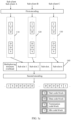
- FIG. 1a is a diagram of an SPN architecture supporting a small granularity technology according to an embodiment of this application.
- the SPN architecture includes: a slicing packet layer (slicing packet layer, SPL), a slicing channel layer (slicing channel layer, SCL), a slicing transport layer (slicing transport layer, STL), a management and control integrated software-defined network (software-defined network, SDN) slicing control plane, and an ultra-high-precision event frequency synchronization technology.
- SPL slicing packet layer
- SCL slicing channel layer
- STL slicing transport layer
- SDN software-defined network
- the SCL includes an FGU layer, an MTN path (MTN path, MTNP) layer, and an MTN section (MTN Section, MTNS) layer.
- the FGU layer provides an end-to-end deterministic low-latency hard slicing path of a granularity of N*10 Mbps for a small-grained service.
- the FGU layer is an independent sublayer, and may be flexibly carried on an MTN path layer or an Ethernet physical layer as required. In other words, a service layer of the FGU layer may be the MTN path layer or the Ethernet physical layer.
- the 10GE Ethernet physical layer can be used in a customer-premises equipment (customer-premises equipment, CPE) scenario, and directly carries the FGU layer.
- CPE customer-premises equipment
- the following describes the MTNS and the MTNP from a perspective of a transmit-side behavior and a receive-side behavior by using an example in which the MTN path layer carries a small-grained service.
- a transmit-side behavior and a receive-side behavior of the MTNS are first described.
- a 100GBASE-R PHY is used as an example.
- the MTNS provides a point-to-point connection, is responsible for performing slot processing on adjacent nodes connected by using an Ethernet PHY, and provides functions of bundling, sub-rating, and channelization.
- the MTNS is bidirectionally symmetric, and one data transmission direction is used as an example for description herein.
- the MTNS inserts a special O code block into a 66B code block sequence, inserts one D code block at an interval of 1023*20 66B code blocks, and inserts one D code block at an interval of 1023*20 66B code blocks.
- a total of seven D code blocks need to be inserted.
- a special O code block is inserted at an interval of 1023*20 code blocks. In this way, a total of 8*(1023*20+1) code blocks form an MTNS frame (frame).
- the O code block and the foregoing seven D code blocks constitute an overhead of the MTNS frame.
- the overhead carries some point-to-point link configuration information that indicates the MTNS, for example, slot configuration information and section layer group configuration information.
- the MTNS continuously sends data to a receive end according to the foregoing frame structure.
- a continuous MTNS frame is equivalent to a 66B code block stream, is converted into a bit, an optical signal, or another analog signal such as an electrical pulse according to the lower PHY layer protocol defined in the Institute of Electrical and Electronics Engineers (Institute of Electrical and Electronics Engineers, IEEE) 802.3, and is sent by a transmit-side device.
- a receive side first locks a received signal (for example, a bit, an optical signal, or another analog signal such as an electrical pulse) as a frame header of the MTNS frame by identifying an O code block. According to a fixed count, it may be learned that a next overhead code block appears after 1023*20 code blocks. Correspondingly, the receive side may determine a location of data corresponding to each slot in the received signal based on the O code block.
- a received signal for example, a bit, an optical signal, or another analog signal such as an electrical pulse
- the MTNS can provide only a point-to-point connection.
- the MTNP is responsible for providing an "end-to-end path connection" from a network ingress to a network egress.
- the MTNP provides an end-to-end rigid hard pipe connection and an operations, administration, and maintenance and protection (OAM and protection, OAMP) function.
- OAM and protection, OAMP operations, administration, and maintenance and protection
- the following describes a transmit-side behavior and a receive-side behavior of the MTNP with reference to FIG. 1b .
- an end-to-end MTNP is included between a provider edge (provider edge, PE) 1 and a PE 2
- a point-to-point MTNS is included between the PE 1 and the PE 2.
- an MTNP layer obtains a client signal from a MAC layer, where the client signal may be a MAC frame.
- MAC mentioned herein may be a processing module at the MAC layer.
- the MTNP layer encodes the MAC frame into a 64/66B code block sequence. Specifically, each MAC frame is encoded into a 66B code block sequence defined by a start code block (S code block) and a termination code block (that is, a T code block), and a MAC frame sequence is encoded into a 66B code block sequence.
- the MTNP fills the 66B code block with I code blocks, to ensure that data is sent in a hard pipe of the MTNP at all times.
- a receive side of a P node first identifies an MTNS frame according to the foregoing receive-side behavior of the MTNS, and then restores MTNP data from a specified MTNS slot according to a preconfiguration.
- the P node performs MTNP forwarding.
- an essential difference between MTNP forwarding and IP forwarding and MAC bridge forwarding lies in that: MTNP forwarding exclusively occupies a device forwarding resource, and does not support statistical multiplexing, and an ingress and an egress of a network node (for example, the P node) need to be configured with a same quantity of MTNS slots.
- a slot corresponding to a large bandwidth may be further divided into a plurality of sub-slots, to carry a small-grained service.
- a slot corresponding to a bandwidth of 5 Gbps is further divided into 480 sub-slots according to a granularity of 10 Mbps.
- the 480 sub-slots are used to carry the small-grained service.
- an MTN FGU may further divide a 5-Gbps MTNP into 480 10-Mbps slots in a hierarchical manner.
- the MTNP and the MTN FGU can be decoupled.
- the MTNP is used as a service layer of the MTN FGU.
- the fg-BU may include an FGU base frame overhead and an FGU base frame payload.
- the FGU base frame overhead may be used to carry small-grained slot information
- the FGU base frame payload is used to carry small-grained service data.
- the small-grained slot information may be a mapping relationship between a sub-slot and a sub-client.
- the sub-client is similar to a FlexE client, and also corresponds to various user interfaces or bandwidths of a network. A difference between the sub-client and the FlexE client lies in that the sub-client represents a client data stream transmitted in the sub-slot, and one sub-client may correspond to one or more sub-slots.
- the MTN FGU layer For an NNI transmit side of the PE 1, similar to the MTNP, the MTN FGU layer first encodes a client signal of the MAC frame into a 66B code block sequence, and then inserts an OAM code block.
- an OAM code block of a fine granularity MTNP (fgMTNP) instead of an OAM code block of the MTNP is inserted into the MTN FGU layer.
- a 66B code block sequence including the OAM code block of the fgMTNP is mapped to a 10-Mbps slot specified in the fg-BU according to a preconfiguration.
- the P node performs fgMTNP forwarding. Similar to MTNP forwarding, fgMTNP forwarding is TDM forwarding, which exclusively occupies a device forwarding resource, and does not support statistical multiplexing. The P node does not terminate the OAM code block of the fgMTNP.
- the transmit-side behavior of the P node is an inverse process of the receive-side behavior of the P node, which is not described in detail herein.
- a receive-side behavior of a PE2 node is an inverse process of a transmit-side behavior of a PE1 node, which is not described in detail herein.
- encoding each MAC frame into a 64/66B code block sequence may include two times of encoding.
- First encoding is to convert the MAC frame into a 66B code block sequence.
- Second encoding is to sequentially fill 66B code blocks corresponding to a plurality of pieces of small-grained data into a data payload part of a D code block of the fgBU and a data payload part of a T code block of the fgBU.
- FIG. 1c is a diagram of a process of encoding a MAC frame according to an embodiment of this application.
- a corresponding 64/66B code block sequence 110 is obtained after an Ethernet frame corresponding to a sub-client A is encoded for the first time.
- a corresponding 64/66B code block sequence 120 may also be obtained, and after an Ethernet frame corresponding to a sub-client C is encoded for the first time, a corresponding 64/66B code block sequence 130 may also be obtained.
- a multiplexing structure 140 including the code block sequence 110, the code block sequence 120, the code block sequence 130, and a multiplexing structure overhead is obtained based on a small-grained slot configuration, the code block sequence 110, the code block sequence 120, and the code block sequence 130.
- the multiplexing structure includes a plurality of sub-slots, and the code block sequence 110, the code block sequence 120, and the code block sequence 130 are filled into corresponding sub-slots in the multiplexing structure 140 based on the small-grained slot configuration.
- secondary encoding is performed on the multiplexing structure 140, and all pieces of bit data included in the multiplexing structure are sequentially filled into 64 bits used as non-synchronization header bits in a 64/66B code block corresponding to the secondary encoding, to obtain a code block stream obtained after the secondary encoding.
- the "64 bits used as the non-synchronization header bits in the 64/66B code block corresponding to the secondary encoding" may also be referred to as a "data payload part", and the two may be used alternately.
- the code block stream obtained after the secondary encoding includes an I code block, an S code block, a D code block, and a T code block.
- the I code block is used to adapt to a rate difference between different Ethernet interfaces.
- For the I code block refer to a related description part in the IEEE 802.3. Details are not described herein.
- the code block sequence 110, the code block sequence 120, and the code block sequence 130 obtained after the first encoding may further include an O code block in addition to an I code block, an S code block, a D code block, and a T code block.
- a 66B code block obtained after the first encoding may be referred to as an “inner code block”
- a 66B code block obtained after the second encoding may be referred to as an “outer code block”.
- the outer code block may include at least one fgBU.
- the fgBU mentioned in embodiments of this application may be an SPN fgBU defined in the China Mobile enterprise standard, or may be an MTN fgBU defined in the international telecommunication union (international telecommunication union, ITU).
- data of one inner code block needs to be carried by using two outer code blocks.
- the first 64 bits of data of an inner code block 1 are carried by using 64 bits of an outer code block 1
- the last 2 bits of data of the inner code block may be carried by using two bits of an outer code block 2.
- the other 62 bits that can be used to carry data in the outer code block 2 may be used to carry 62 bits of data of the inner code block 2.
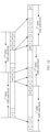
- FIG. 1d is a diagram of an outer code block and an inner code block according to an embodiment of this application.
- the first 64 bits of the 1 st inner 66 code block are carried by using the 2 nd bit to the 63 rd bit of the 1 st outer code block
- the last two bits of the 1 st inner 66B code block are carried by using the 2 nd bit and the 3 rd bit of the 2 nd outer code block
- the first 62 bits of the 2 nd inner 66B code block are carried by using the 4 th bit to the 65 th bit of the 2 nd outer code block
- the last 4 bits of the 2 nd inner 66B code block are carried by using the 2 nd bit to the 5 th bit of the 3 rd outer code block, and so on.
- the MAC frame is encoded in the 64/66B encoding manner in the foregoing descriptions, the foregoing descriptions are merely shown as a possible implementation, and an encoding technology used for encoding the MAC frame is not limited to the foregoing 64/65B encoding manner.
- the MAC frame may be encoded in a 64/65B encoding manner.
- the MAC frame may be encoded in a 256/257B encoding manner. Details are not described herein.
- the 64/66B encoding manner is used as an example for description.
- FIG. 1e is a diagram of an example application scenario according to an embodiment of this application.
- an end-to-end transmission path is established between a PE 1 and a PE 2 to carry a small-grained service.
- a device P1 and a device P2 are further included between the PE 1 and the PE 2.
- another device may also be included between the PE 1 and the device P1.
- another device may also be included between the device P1 and the device P2 or between the device P2 and the device PE2.
- a transmission error may occur in a transmission process of a small-grained service.
- a transmission error may occur in an fgBU.
- a D code block, an I code block, an O code block, and a T code block in the fgBU may all change into E code blocks. If processing is not performed when an outer code block is an E code block, bit error spreading may be caused, and normal transmission of a small-grained service is affected.
- embodiments of this application provide an error code block processing method and apparatus, to avoid bit error spreading.
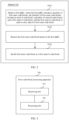
- FIG. 2 is a schematic flowchart of an error code block processing method according to an embodiment of this application.
- the error code block processing method shown in FIG. 2 may be performed by a first communication apparatus using a FlexE fine granularity technology.
- the first communication apparatus may be a fine-grained service switching node.
- the fine-grained service switching node is an intermediate node that has a fine-grained service parsing function.
- the fine-grained service switching node may be P1 shown in FIG. 1e .
- the first communication apparatus may alternatively be a fine-grained service sink node.
- the fine-grained service sink node may be a tail node that receives a fine-grained service packet.
- the fine-grained service sink node may be PE2 shown in FIG. 1e .
- the method 100 may be performed by an inbound interface of the first communication apparatus. In another example, the method 100 may be performed by an outbound interface of the first communication apparatus. In still another example, some steps of the method 100 may be performed by the inbound interface, and some steps may be performed by the outbound interface. This is not specifically limited in this embodiment of this application.
- Communication apparatuses mentioned in embodiments of this application may be network devices such as switches or routers, or may be some components on the network device, for example, boards or line cards on the network device, or may be some function modules on the network device, or may be chips configured to implement the method in this application. This is not specifically limited in embodiments of this application.
- the communication apparatuses may be directly connected, for example, but not limited to, by using an Ethernet cable or an optical cable.
- S101 Obtain a first fgBU, where the first fgBU includes a plurality of first outer code blocks, the plurality of first outer code blocks include an outer S code block, a plurality of outer D code blocks, and a first outer E code block, and the first outer E code block is used to carry data of a first inner code block.
- the first communication apparatus may first obtain a code block stream including a plurality of outer code blocks, and then analyze the code block stream to obtain the first fgBU.
- the inbound interface may receive the code block stream that includes the plurality of outer code blocks and that is sent by an upstream node (for example, a PE1 node).
- an upstream node for example, a PE1 node
- the outbound interface may obtain the code block stream based on data transmitted by the inbound interface of the first communication apparatus to the outbound interface.
- a first outer E code block in the code block stream may be first identified, and then an fgBU to which the first outer E code block belongs is further determined, to determine the first fgBU.
- an E code block may be matched against the code block stream, to determine the first outer E code block in the code block stream.
- a FlexE overhead in the code block stream may be first identified to locate a FlexE frame in the code block stream, an MTNP data stream is restored from each slot of the FlexE frame based on a fine-grained slot configuration, and at least one fgBU is restored based on the MTNP data stream; and then, the fgBU corresponding to the first outer E code block is determined as the first fgBU.
- At least one fgBU may be first obtained based on the code block stream, and then the at least one fgBU is analyzed separately to determine whether each fgBU includes an E code block, to obtain the first fgBU including the first outer E code block.
- the first outer E code block may be a first outer D code block in which an error occurs, or may be a first outer T code block in which an error occurs.
- the inner code block may include an S code block, a D code block, and a T code block, and may further include an idle I code block and/or an O code block. Therefore, the first inner code block may be any one of an S code block, a D code block, a T code block, an idle I code block, and an O code block.
- a specific implementation of restoring the first inner code block based on the first fgBU is an inverse process of filling the first inner code block into a data payload field of an outer code block.
- a data payload part in the first fgBU may be extracted, and after the data payload part is concatenated, a corresponding inner 66B code block is restored.
- the inner 66B code block corresponding to the first fgBU is obtained, the inner 66B code block corresponding to the first outer E code block may be determined as the first inner code block.
- the first outer E code block and the first inner code block are described by using an example with reference to FIG. 1d .
- the first outer E code block may be the 1 st outer 66B code block shown in FIG. 1d
- the first inner code block may be the 1 st inner 66B code block shown in FIG. 1d
- the first outer code block may be the 2 nd outer 66B code block shown in FIG. 1d
- the first inner code block may be the 1 st inner 66B code block or the 2 nd inner 66B code block shown in FIG. 1d .
- the first inner code block may be carried in a first sub-slot.
- the first sub-slot may be used to carry data corresponding to a sub-client, data carried in the first sub-slot may include a plurality of inner code blocks, and the first inner code block may be one of the plurality of inner code blocks.
- S 102 may be performed by the inbound interface of the first communication apparatus, or may be performed by the outbound interface of the first communication apparatus.
- the first inner code block may be set as the first inner E code block.
- S103 may be performed by the inbound interface of the first communication apparatus, or may be performed by the outbound interface of the first communication apparatus.
- the inbound interface may add a tag to the first inner code block.
- the outbound interface sets the first inner code block as the first inner E code block based on the tag.
- the first inner code block may correspond to a first sub-slot, and the first sub-slot may correspond to a plurality of inner code blocks.
- the plurality of inner code blocks corresponding to the first sub-slot may be all set as inner E code blocks.
- the first inner code block may be set as the first inner E code block, and an inner code block other than the first inner code block in the plurality of inner code blocks corresponding to the first sub-slot may not be processed.
- some code blocks in the plurality of inner code blocks corresponding to the first sub-slot may be set as inner E code blocks, and the some code blocks may include the first inner code block.
- the first inner code block and several inner code blocks adjacent to the first inner code block in the plurality of inner code blocks corresponding to the first sub-slot may be set as inner E code blocks.
- the first communication apparatus may be a fine-grained service switching node.
- the first communication apparatus may send the first inner E code block to a second communication apparatus.
- the first communication apparatus may send the code block stream including the first inner E code block to the second communication apparatus.
- the code block stream including the first inner E code block may be a code block stream obtained after secondary encoding. For secondary encoding, refer to the foregoing related description part. Details are not described herein again.
- the first communication apparatus may be a fine-grained service sink node.
- the first communication apparatus may send the first inner E code block to an Ethernet frame client signal restoration module of the first communication apparatus.
- the first communication apparatus may send, for example, a multiplexing structure including the first inner E code block to the Ethernet frame client signal restoration module, so that the Ethernet frame client signal restoration module performs data restoration on the received multiplexing structure to obtain data corresponding to each client (sub-client), that is, obtain an Ethernet frame corresponding to each client.
- the Ethernet frame client signal restoration module may discard the first inner E code block, instead of processing the first inner E code block as a normal code block. Therefore, bit error spreading can be avoided.
- one outer code block may correspond to one or two inner code blocks. Therefore, in an example, the first outer E code block may further carry a second inner code block in addition to the first inner code block.
- the first outer code block E may correspond to the 1 st inner code block and the 2 nd inner code block.
- the first communication apparatus may further perform steps A1 and A2.
- Step A1 Restore the second inner code block based on the first fgBU.
- Step A2 Set the second inner code block as a second inner E code block.
- steps A1 and A2 refer to specific implementation parts of S102 and S103 in the method 100. Details are not described herein again.
- the first communication apparatus may further send the second inner E code block to the second communication apparatus in addition to sending the first inner code block to the second communication apparatus.
- the first communication apparatus may send the code block stream including the first inner E code block and the second inner E code block to the second communication apparatus.
- the code block stream including the first inner E code block and the second inner E code block may be a code block stream obtained after secondary encoding. For secondary encoding, refer to the foregoing related description part. Details are not described herein again.
- the plurality of first outer code blocks included in the first fgBU may further include a second outer E code block in addition to the first outer E code block.
- the second outer E code block may be a second outer D code block in which an error occurs, and the second outer E code block is used to carry data of a third inner code block.
- the first communication apparatus may further perform steps B1 and B2.
- Step B1 Restore the third inner code block based on the first fgBU.
- Step B2 Set the third inner code block as a third inner E code block.
- Performing steps B1 and B2 can avoid bit error spreading caused because the third inner code block is not set as an E code block.
- steps B1 and B2 refer to specific implementation parts of S102 and S103 in the method 100. Details are not described herein again.
- the first communication apparatus may further send the third inner E code block to the second communication apparatus in addition to sending the first inner code block to the second communication apparatus.
- the first communication apparatus may send the code block stream including the first inner E code block and the third inner E code block to the second communication apparatus.
- the code block stream including the first inner E code block and the third inner E code block may be a code block stream obtained after secondary encoding. For secondary encoding, refer to the foregoing related description part. Details are not described herein again.
- the first communication apparatus may further send the third inner E code block to the Ethernet frame client signal restoration module of the first communication apparatus in addition to sending the first inner code block to the Ethernet frame client signal restoration module of the first communication apparatus.
- the first communication apparatus may send, for example, a multiplexing structure including the first inner E code block and the third inner E code block to the Ethernet frame client signal restoration module, so that the Ethernet frame client signal restoration module performs data restoration on the received multiplexing structure to obtain data corresponding to each sub-client.
- another fgBU may also include an outer E code block (for example, the first outer E code block and the second outer E code block).
- the first communication apparatus may further perform steps C1 to C3.
- Step C1 Obtain a second fgBU, where the second fgBU includes a plurality of second outer code blocks, the plurality of second outer code blocks include an outer S code block, a plurality of outer D code blocks, and a fourth outer E code block, and the fourth outer E code block is used to carry data of a fourth inner code block.
- Step C2 Restore the fourth inner code block based on the second fgBU.
- Step C3 Set the fourth inner code block as a fourth inner E code block.
- steps C1 to C3 For specific implementation of steps C1 to C3, refer to the foregoing specific description parts of the method 100. Details are not described herein again.
- the first communication apparatus may further send the fourth inner E code block to the second communication apparatus.
- the first communication apparatus may further send the fourth inner E code block to the Ethernet frame client signal restoration module of the first communication apparatus.
- An embodiment of this application further provides an error code block processing apparatus.
- the apparatus may be used in a first communication apparatus using a FlexE fine granularity technology.
- the error code block processing apparatus may include a transceiver unit and a processing unit.
- the transceiver unit is configured to perform a receiving-related operation and/or a sending-related operation performed by the first communication apparatus in the possible implementations of the foregoing method embodiments.
- the processing unit is configured to perform an operation other than the receiving-related operation and/or the sending-related operation performed by the first communication apparatus in the possible implementations of the foregoing method embodiments.
- the transceiver unit may include a receiving unit and/or a sending unit.
- the receiving unit is configured to perform the receiving-related operation
- the sending unit is configured to perform the sending-related operation.
- FIG. 3 is a diagram of a structure of an error code block processing apparatus according to an embodiment of this application.
- the error code block processing apparatus 300 may include a receiving unit 301 and a processing unit 302.
- the receiving unit 301 is configured to obtain a first fine granularity basic unit fgBU, where the first fgBU includes a plurality of first outer code blocks, the plurality of first outer code blocks include an outer start S code block, a plurality of outer data D code blocks, and a first outer error E code block, and the first outer E code block is used to carry data of a first inner code block.
- the processing unit 302 is configured to: restore the first inner code block based on the first fgBU; and set the first inner code block as a first inner E code block.
- the first inner code block corresponds to a first sub-slot
- the setting the first inner code block as a first inner E code block includes: setting a plurality of inner code blocks corresponding to the first sub-slot as inner E code blocks, where the plurality of inner code blocks include the first inner code block.
- the plurality of first outer code blocks further include a termination T code block, and the first outer E code block is a first outer D code block in which an error occurs.
- the first outer E code block is a T code block in which an error occurs.
- the first communication apparatus is a fine-grained service switching node, and the apparatus further includes: a sending unit, configured to send the first inner E code block to a second communication apparatus.
- the first communication apparatus is a fine-grained service sink node, and the apparatus further includes: a sending unit, configured to send the first inner E code block to an Ethernet frame client signal restoration module of the first communication apparatus.
- the first outer E code block is further used to carry data of a second inner code block
- the processing unit 302 is further configured to: restore the second inner code block based on the first fgBU, and set the second inner code block as a second inner E code block.
- the first communication apparatus is the fine-grained service switching node
- the sending unit included in the apparatus is further configured to send the second inner E code block to the second communication apparatus.
- the first communication apparatus is the fine-grained service sink node
- the sending unit included in the apparatus is further configured to send the second inner E code block to the Ethernet frame client signal restoration module of the first communication apparatus.
- the plurality of first outer code blocks further include a second outer E code block, the second outer E code block is a second outer D code block in which an error occurs, and the second outer E code block is used to carry data of a third inner code block.
- the processing unit is further configured to: restore the third inner code block based on the first fgBU, and set the third inner code block as a third inner E code block
- the receiving unit 301 is further configured to obtain a second fgBU, where the second fgBU includes a plurality of second outer code blocks, the plurality of second outer code blocks include an outer S code block, a plurality of outer D code blocks, and a fourth outer E code block, and the fourth outer E code block is used to carry data of a fourth inner code block.
- the processing unit is further configured to: restore the fourth inner code block based on the second fgBU, and set the fourth inner code block to a fourth inner E code block.
- the first inner code block includes any one of the following types of code blocks: an S code block, a D code block, a T code block, an idle I code block, or an O code block.
- the first communication apparatus is the fine-grained service switching node
- the setting the first inner code block as a first inner E code block includes: An outbound interface of the first communication apparatus sets the first inner code block as the first inner E code block.
- the apparatus 300 is an apparatus corresponding to the method performed by the first communication apparatus provided in the foregoing method embodiment, and specific implementation of each unit of the apparatus 300 has a same concept as the foregoing method embodiment. Therefore, for specific implementation of each unit of the apparatus 300, refer to the descriptions in the foregoing method embodiment. Details are not described herein again.
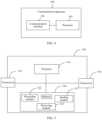
- FIG. 4 is a diagram of a structure of a communication apparatus according to an embodiment of this application.
- the communication apparatus 400 includes a communication interface 401 and a processor 402 connected to the communication interface 401.
- the communication apparatus 400 may be configured to perform the method 10 in the foregoing embodiment.
- the communication apparatus 400 may perform the method 100 in the foregoing embodiment.
- the communication apparatus 400 is equivalent to the first communication apparatus in the method 100.
- the communication interface 401 is configured to perform a receiving/sending operation performed by the first communication apparatus in the method 100.
- the processor 402 is configured to perform an operation other than the receiving/sending operation performed by the first communication apparatus in the method 100.
- the communication interface 401 is configured to obtain a first fgBU, where the first fgBU includes a plurality of first outer code blocks, the plurality of first outer code blocks include an outer S code block, a plurality of outer D code blocks, and a first outer E code block, and the first outer E code block is used to carry data of a first inner code block.
- the processor 402 is configured to: restore the first inner code block based on the first fgBU; and set the first inner code block as a first inner E code block.
- FIG. 5 is a diagram of a structure of a communication apparatus according to an embodiment of this application.
- the communication apparatus 500 may be configured to perform the method 100 in the foregoing embodiment.
- the communication apparatus 500 may include a processor 510, a memory 520 coupled to the processor 510, and a transceiver 530.
- the transceiver 530 may be, for example, a communication interface or an optical module.
- the processor 510 may be a central processing unit (central processing unit, CPU), a network processor (network processor, NP), or a combination of the CPU and the NP.
- the processor may alternatively be an application-specific integrated circuit (application-specific integrated circuit, ASIC), a programmable logic device (programmable logic device, PLD), or a combination thereof.
- the PLD may be a complex programmable logic device (complex programmable logic device, CPLD), a field-programmable gate array (field-programmable gate array, FPGA), generic array logic (generic array logic, GAL), or any combination thereof.
- processors 510 may include a volatile memory (English: volatile memory), for example, a random-access memory (English: random-access memory, RAM for short).
- the memory may alternatively include a non-volatile memory (English: non-volatile memory), for example, a read-only memory (read-only memory, ROM), a flash memory (English: flash memory), a hard disk drive (hard disk drive, HDD), or a solid-state drive (solid-state drive, SSD).
- the memory 520 may alternatively include a combination of the foregoing types of memories. There may be one or more memories 520.
- the memory 520 stores computer-readable instructions, and the computer-readable instructions include a plurality of software modules, for example, a sending module 521, a processing module 522, and a receiving module 523.
- the processor 510 may perform a corresponding operation according to an indication of each software module. In this embodiment, an operation performed by a software module is actually an operation performed by the processor 510 according to an indication of the software module.
- the communication apparatus 500 may perform the method 100 in the foregoing embodiment.
- the communication apparatus 500 is equivalent to the first communication apparatus in the method 100.
- the transceiver 530 is configured to perform a receiving/sending operation performed by the first communication apparatus in the method 100.
- the processor 510 is configured to perform an operation other than the receiving/sending operation performed by the first communication apparatus in the method 100.
- the transceiver 530 is configured to obtain a first fgBU, where the first fgBU includes a plurality of first outer code blocks, the plurality of first outer code blocks include an outer S code block, a plurality of outer D code blocks, and a first outer E code block, and the first outer E code block is used to carry data of a first inner code block.
- the processor 510 is configured to: restore the first inner code block based on the first fgBU; and set the first inner code block as a first inner E code block.
- This application further provides a computer-readable storage medium.
- the computer-readable storage medium stores instructions. When the instructions are run on a computer, the computer is enabled to perform any one or more operations in the method (for example, the method 100) in the foregoing embodiment.
- the disclosed system, apparatus, and method may be implemented in other manners.
- the described apparatus embodiments are merely examples.
- division into the units is merely logical service division.
- a plurality of units or components may be combined or integrated into another system, or some features may be ignored or not performed.
- the displayed or discussed mutual couplings or direct couplings or communication connections may be implemented by using some interfaces.
- the indirect couplings or communication connections between the apparatuses or units may be implemented in electronic, mechanical, or other forms.
- the units described as separate parts may or may not be physically separate, and parts displayed as units may or may not be physical units, in other words, may be located in one position, or may be distributed on a plurality of network units. Some or all of the units may be selected based on actual requirements to achieve the objectives of the solutions of embodiments.
- service units in embodiments of this application may be integrated into one processing unit, or each unit may exist alone physically, or two or more units may be integrated into one unit.
- the integrated unit may be implemented in a form of hardware, or may be implemented in a form of a software service unit.
- the integrated unit When the integrated unit is implemented in a form of a software service unit and sold or used as an independent product, the integrated unit may be stored in a computer-readable storage medium.
- the computer software product is stored in a storage medium and includes several instructions for instructing a computer device (which may be a personal computer, a server, or a network device) to perform all or some of the steps of the methods described in embodiments of this application.
- the storage medium includes any medium that can store program code, such as a USB flash drive, a removable hard disk, a read-only memory (ROM, Read-Only Memory), a random access memory (RAM, Random Access Memory), a magnetic disk, or an optical disc.
- services described in the present invention may be implemented by hardware, software, firmware, or any combination thereof. When implemented by software, these services may be stored in a computer-readable medium or transmitted as one or more instructions or code on the computer-readable medium.
- the computer-readable medium includes a computer storage medium and a communications medium, where the communications medium includes any medium that enables a computer program to be transmitted from one place to another.
- the storage medium may be any available medium accessible to a general-purpose or a dedicated computer.
Landscapes
- Engineering & Computer Science (AREA)
- Computer Networks & Wireless Communication (AREA)
- Signal Processing (AREA)
- Quality & Reliability (AREA)
- Physics & Mathematics (AREA)
- Spectroscopy & Molecular Physics (AREA)
- Data Exchanges In Wide-Area Networks (AREA)
- Detection And Prevention Of Errors In Transmission (AREA)
Applications Claiming Priority (2)
| Application Number | Priority Date | Filing Date | Title |
|---|---|---|---|
| CN202210945854.1A CN117579220A (zh) | 2022-08-08 | 2022-08-08 | 一种故障码块处理方法及装置 |
| PCT/CN2023/103322 WO2024032191A1 (fr) | 2022-08-08 | 2023-06-28 | Procédé et dispositif de traitement de bloc de code de défaut |
Publications (2)
| Publication Number | Publication Date |
|---|---|
| EP4557645A1 true EP4557645A1 (fr) | 2025-05-21 |
| EP4557645A4 EP4557645A4 (fr) | 2025-10-22 |
Family
ID=89850614
Family Applications (1)
| Application Number | Title | Priority Date | Filing Date |
|---|---|---|---|
| EP23851418.6A Pending EP4557645A4 (fr) | 2022-08-08 | 2023-06-28 | Procédé et dispositif de traitement de bloc de code de défaut |
Country Status (4)
| Country | Link |
|---|---|
| US (1) | US20250184038A1 (fr) |
| EP (1) | EP4557645A4 (fr) |
| CN (1) | CN117579220A (fr) |
| WO (1) | WO2024032191A1 (fr) |
Families Citing this family (2)
| Publication number | Priority date | Publication date | Assignee | Title |
|---|---|---|---|---|
| CN115021875A (zh) * | 2021-03-05 | 2022-09-06 | 华为技术有限公司 | 确定传输时隙的方法和相关装置 |
| CN119109893B (zh) * | 2024-09-23 | 2025-09-09 | 武汉烽火技术服务有限公司 | 业务无损切换方法及装置 |
Family Cites Families (8)
| Publication number | Priority date | Publication date | Assignee | Title |
|---|---|---|---|---|
| CN113316037B (zh) * | 2017-05-02 | 2022-08-09 | 华为技术有限公司 | 一种业务承载的方法、设备和系统 |
| CN112468259B (zh) * | 2019-09-09 | 2023-12-15 | 华为技术有限公司 | 一种通信方法、设备及存储介质 |
| CN112953675A (zh) * | 2019-12-10 | 2021-06-11 | 华为技术有限公司 | 一种数据传输方法、通信设备及存储介质 |
| CN113938245A (zh) * | 2020-07-13 | 2022-01-14 | 华为技术有限公司 | 一种速率适配方法及装置 |
| CN113938247A (zh) * | 2020-07-14 | 2022-01-14 | 中国移动通信有限公司研究院 | 一种码块处理方法、节点及介质 |
| CN112491499A (zh) * | 2020-10-22 | 2021-03-12 | 中兴通讯股份有限公司 | 数据发送方法及装置、存储介质、电子装置 |
| CN114584255A (zh) * | 2020-11-30 | 2022-06-03 | 华为技术有限公司 | 一种码块识别方法及装置 |
| WO2024000378A1 (fr) * | 2022-06-30 | 2024-01-04 | 华为技术有限公司 | Procédé et appareil d'identification de bloc de code |
-
2022
- 2022-08-08 CN CN202210945854.1A patent/CN117579220A/zh active Pending
-
2023
- 2023-06-28 WO PCT/CN2023/103322 patent/WO2024032191A1/fr not_active Ceased
- 2023-06-28 EP EP23851418.6A patent/EP4557645A4/fr active Pending
-
2025
- 2025-02-07 US US19/048,142 patent/US20250184038A1/en active Pending
Also Published As
| Publication number | Publication date |
|---|---|
| WO2024032191A1 (fr) | 2024-02-15 |
| US20250184038A1 (en) | 2025-06-05 |
| EP4557645A4 (fr) | 2025-10-22 |
| CN117579220A (zh) | 2024-02-20 |
Similar Documents
| Publication | Publication Date | Title |
|---|---|---|
| JP7594087B2 (ja) | データ伝送方法及びデバイス | |
| US11316545B2 (en) | Data transmission method, communications device, and storage medium | |
| CN109600188B (zh) | 数据传输方法、传输设备和传输系统 | |
| US20250184038A1 (en) | Error Code Block Processing Method and Apparatus | |
| JP7282187B2 (ja) | フレキシブルイーサネット通信方法及びネットワーク装置 | |
| EP3687088A1 (fr) | Procédé de transmission de données dans un réseau optique, et dispositif de réseau optique | |
| US8416770B2 (en) | Universal service transport transitional encoding | |
| KR102371144B1 (ko) | 데이터 송신 방법, 통신 디바이스, 및 저장 매체 | |
| US20250184032A1 (en) | Communication method, related apparatus, and computer-readable storage medium | |
| WO2023109424A1 (fr) | Procédé de transmission de données et dispositif associé | |
| WO2022062930A1 (fr) | Procédé et dispositif de traitement de flux de blocs de code | |
| WO2023197770A1 (fr) | Procédé et appareil de notification de défaut | |
| EP3905593A1 (fr) | Procédé de communication ethernet flexible et dispositif réseau | |
| WO2023035776A1 (fr) | Procédé de communication, appareil correspondant et support de stockage | |
| EP4239918A1 (fr) | Procédé et appareil de reconnaissance de blocs de code | |
| CN118677718A (zh) | 一种数据处理方法及装置 | |
| CN118055076A (zh) | 一种报文处理方法、信息处理方法及装置 | |
| EP4254843A1 (fr) | Procédé et appareil de traitement de trame de surdébit ethernet flexible | |
| EP4344147A1 (fr) | Procédé et appareil de négociation d'intervalle de temps | |
| WO2024087975A1 (fr) | Procédé et appareil de communication | |
| CN116962145A (zh) | 一种故障通告方法及装置 | |
| EP4694053A1 (fr) | Procédé et appareil de traitement de données, et système de communication | |
| CN120075062A (zh) | 城域传输网大颗粒帧格式设计方法、业务处理方法及网络 |
Legal Events
| Date | Code | Title | Description |
|---|---|---|---|
| STAA | Information on the status of an ep patent application or granted ep patent |
Free format text: STATUS: THE INTERNATIONAL PUBLICATION HAS BEEN MADE |
|
| PUAI | Public reference made under article 153(3) epc to a published international application that has entered the european phase |
Free format text: ORIGINAL CODE: 0009012 |
|
| STAA | Information on the status of an ep patent application or granted ep patent |
Free format text: STATUS: REQUEST FOR EXAMINATION WAS MADE |
|
| 17P | Request for examination filed |
Effective date: 20250212 |
|
| AK | Designated contracting states |
Kind code of ref document: A1 Designated state(s): AL AT BE BG CH CY CZ DE DK EE ES FI FR GB GR HR HU IE IS IT LI LT LU LV MC ME MK MT NL NO PL PT RO RS SE SI SK SM TR |
|
| A4 | Supplementary search report drawn up and despatched |
Effective date: 20250919 |
|
| RIC1 | Information provided on ipc code assigned before grant |
Ipc: H04L 1/00 20060101AFI20250915BHEP Ipc: H04J 3/16 20060101ALI20250915BHEP |
|
| DAV | Request for validation of the european patent (deleted) | ||
| DAX | Request for extension of the european patent (deleted) |