EP4557842A1 - Procédé de transmission d'informations, et appareil - Google Patents
Procédé de transmission d'informations, et appareil Download PDFInfo
- Publication number
- EP4557842A1 EP4557842A1 EP23851443.4A EP23851443A EP4557842A1 EP 4557842 A1 EP4557842 A1 EP 4557842A1 EP 23851443 A EP23851443 A EP 23851443A EP 4557842 A1 EP4557842 A1 EP 4557842A1
- Authority
- EP
- European Patent Office
- Prior art keywords
- antenna panel
- transmit power
- power
- terminal device
- antenna
- Prior art date
- Legal status (The legal status is an assumption and is not a legal conclusion. Google has not performed a legal analysis and makes no representation as to the accuracy of the status listed.)
- Pending
Links
Images





Classifications
-
- H—ELECTRICITY
- H04—ELECTRIC COMMUNICATION TECHNIQUE
- H04W—WIRELESS COMMUNICATION NETWORKS
- H04W52/00—Power management, e.g. Transmission Power Control [TPC] or power classes
- H04W52/04—Transmission power control [TPC]
- H04W52/38—TPC being performed in particular situations
- H04W52/42—TPC being performed in particular situations in systems with time, space, frequency or polarisation diversity
-
- H—ELECTRICITY
- H04—ELECTRIC COMMUNICATION TECHNIQUE
- H04B—TRANSMISSION
- H04B7/00—Radio transmission systems, i.e. using radiation field
- H04B7/02—Diversity systems; Multi-antenna system, i.e. transmission or reception using multiple antennas
- H04B7/04—Diversity systems; Multi-antenna system, i.e. transmission or reception using multiple antennas using two or more spaced independent antennas
- H04B7/0404—Diversity systems; Multi-antenna system, i.e. transmission or reception using multiple antennas using two or more spaced independent antennas the mobile station comprising multiple antennas, e.g. to provide uplink diversity
-
- H—ELECTRICITY
- H04—ELECTRIC COMMUNICATION TECHNIQUE
- H04B—TRANSMISSION
- H04B7/00—Radio transmission systems, i.e. using radiation field
- H04B7/02—Diversity systems; Multi-antenna system, i.e. transmission or reception using multiple antennas
- H04B7/04—Diversity systems; Multi-antenna system, i.e. transmission or reception using multiple antennas using two or more spaced independent antennas
- H04B7/0413—MIMO systems
- H04B7/0456—Selection of precoding matrices or codebooks, e.g. using matrices antenna weighting
- H04B7/046—Selection of precoding matrices or codebooks, e.g. using matrices antenna weighting taking physical layer constraints into account
- H04B7/0465—Selection of precoding matrices or codebooks, e.g. using matrices antenna weighting taking physical layer constraints into account taking power constraints at power amplifier or emission constraints, e.g. constant modulus, into account
-
- H—ELECTRICITY
- H04—ELECTRIC COMMUNICATION TECHNIQUE
- H04B—TRANSMISSION
- H04B7/00—Radio transmission systems, i.e. using radiation field
- H04B7/02—Diversity systems; Multi-antenna system, i.e. transmission or reception using multiple antennas
- H04B7/04—Diversity systems; Multi-antenna system, i.e. transmission or reception using multiple antennas using two or more spaced independent antennas
- H04B7/06—Diversity systems; Multi-antenna system, i.e. transmission or reception using multiple antennas using two or more spaced independent antennas at the transmitting station
- H04B7/0613—Diversity systems; Multi-antenna system, i.e. transmission or reception using multiple antennas using two or more spaced independent antennas at the transmitting station using simultaneous transmission
- H04B7/0615—Diversity systems; Multi-antenna system, i.e. transmission or reception using multiple antennas using two or more spaced independent antennas at the transmitting station using simultaneous transmission of weighted versions of same signal
- H04B7/0617—Diversity systems; Multi-antenna system, i.e. transmission or reception using multiple antennas using two or more spaced independent antennas at the transmitting station using simultaneous transmission of weighted versions of same signal for beam forming
-
- H—ELECTRICITY
- H04—ELECTRIC COMMUNICATION TECHNIQUE
- H04B—TRANSMISSION
- H04B7/00—Radio transmission systems, i.e. using radiation field
- H04B7/02—Diversity systems; Multi-antenna system, i.e. transmission or reception using multiple antennas
- H04B7/04—Diversity systems; Multi-antenna system, i.e. transmission or reception using multiple antennas using two or more spaced independent antennas
- H04B7/06—Diversity systems; Multi-antenna system, i.e. transmission or reception using multiple antennas using two or more spaced independent antennas at the transmitting station
- H04B7/0613—Diversity systems; Multi-antenna system, i.e. transmission or reception using multiple antennas using two or more spaced independent antennas at the transmitting station using simultaneous transmission
- H04B7/0615—Diversity systems; Multi-antenna system, i.e. transmission or reception using multiple antennas using two or more spaced independent antennas at the transmitting station using simultaneous transmission of weighted versions of same signal
- H04B7/0619—Diversity systems; Multi-antenna system, i.e. transmission or reception using multiple antennas using two or more spaced independent antennas at the transmitting station using simultaneous transmission of weighted versions of same signal using feedback from receiving side
- H04B7/0621—Feedback content
- H04B7/0623—Auxiliary parameters, e.g. power control [PCB] or not acknowledged commands [NACK], used as feedback information
-
- H—ELECTRICITY
- H04—ELECTRIC COMMUNICATION TECHNIQUE
- H04B—TRANSMISSION
- H04B7/00—Radio transmission systems, i.e. using radiation field
- H04B7/02—Diversity systems; Multi-antenna system, i.e. transmission or reception using multiple antennas
- H04B7/04—Diversity systems; Multi-antenna system, i.e. transmission or reception using multiple antennas using two or more spaced independent antennas
- H04B7/06—Diversity systems; Multi-antenna system, i.e. transmission or reception using multiple antennas using two or more spaced independent antennas at the transmitting station
- H04B7/0613—Diversity systems; Multi-antenna system, i.e. transmission or reception using multiple antennas using two or more spaced independent antennas at the transmitting station using simultaneous transmission
- H04B7/0615—Diversity systems; Multi-antenna system, i.e. transmission or reception using multiple antennas using two or more spaced independent antennas at the transmitting station using simultaneous transmission of weighted versions of same signal
- H04B7/0619—Diversity systems; Multi-antenna system, i.e. transmission or reception using multiple antennas using two or more spaced independent antennas at the transmitting station using simultaneous transmission of weighted versions of same signal using feedback from receiving side
- H04B7/0621—Feedback content
- H04B7/063—Parameters other than those covered in groups H04B7/0623 - H04B7/0634, e.g. channel matrix rank or transmit mode selection
-
- H—ELECTRICITY
- H04—ELECTRIC COMMUNICATION TECHNIQUE
- H04B—TRANSMISSION
- H04B7/00—Radio transmission systems, i.e. using radiation field
- H04B7/02—Diversity systems; Multi-antenna system, i.e. transmission or reception using multiple antennas
- H04B7/04—Diversity systems; Multi-antenna system, i.e. transmission or reception using multiple antennas using two or more spaced independent antennas
- H04B7/06—Diversity systems; Multi-antenna system, i.e. transmission or reception using multiple antennas using two or more spaced independent antennas at the transmitting station
- H04B7/0686—Hybrid systems, i.e. switching and simultaneous transmission
- H04B7/0695—Hybrid systems, i.e. switching and simultaneous transmission using beam selection
- H04B7/06952—Selecting one or more beams from a plurality of beams, e.g. beam training, management or sweeping
- H04B7/06956—Selecting one or more beams from a plurality of beams, e.g. beam training, management or sweeping using a selection of antenna panels
-
- H—ELECTRICITY
- H04—ELECTRIC COMMUNICATION TECHNIQUE
- H04W—WIRELESS COMMUNICATION NETWORKS
- H04W52/00—Power management, e.g. Transmission Power Control [TPC] or power classes
- H04W52/04—Transmission power control [TPC]
- H04W52/30—Transmission power control [TPC] using constraints in the total amount of available transmission power
- H04W52/36—Transmission power control [TPC] using constraints in the total amount of available transmission power with a discrete range or set of values, e.g. step size, ramping or offsets
-
- H—ELECTRICITY
- H04—ELECTRIC COMMUNICATION TECHNIQUE
- H04W—WIRELESS COMMUNICATION NETWORKS
- H04W52/00—Power management, e.g. Transmission Power Control [TPC] or power classes
- H04W52/04—Transmission power control [TPC]
- H04W52/30—Transmission power control [TPC] using constraints in the total amount of available transmission power
- H04W52/36—Transmission power control [TPC] using constraints in the total amount of available transmission power with a discrete range or set of values, e.g. step size, ramping or offsets
- H04W52/365—Power headroom reporting
-
- H—ELECTRICITY
- H04—ELECTRIC COMMUNICATION TECHNIQUE
- H04W—WIRELESS COMMUNICATION NETWORKS
- H04W52/00—Power management, e.g. Transmission Power Control [TPC] or power classes
- H04W52/04—Transmission power control [TPC]
- H04W52/30—Transmission power control [TPC] using constraints in the total amount of available transmission power
- H04W52/36—Transmission power control [TPC] using constraints in the total amount of available transmission power with a discrete range or set of values, e.g. step size, ramping or offsets
- H04W52/367—Power values between minimum and maximum limits, e.g. dynamic range
Definitions
- This application relates to the communication field, and more specifically, to an information transmission method and an apparatus.
- a high frequency band (usually greater than 6 GHz) like 28 GHz, 39 GHz, or 60 GHz is usually used in 5G NR (new radio, NR), to meet requirements of three scenarios.
- a larger bandwidth and a higher transmission rate are achieved by introducing a high frequency. Because the frequency is high, a signal may severely fade during propagation in space. Therefore, a beamforming (beamforming, BF) technology is used in 5G NR to obtain a good directional gain, to increase a directional power in a transmit direction and improve a signal to interference plus noise ratio (signal to interference plus noise radio, SINR) at a receive end. Therefore, system performance is further improved.
- SINR signal to interference plus noise radio
- a hybrid beamforming technology including digital beamforming and analog beamforming is usually used.
- an antenna panel (antenna panel) is a core component. A beam is sent or received by using the antenna panel.
- a directional beam is used.
- a base station and a terminal are both deployed by using a plurality of antenna panels. Especially, for the terminal, to meet coverage and in a case of limited space and cost saving, antenna panel deployment has more important impact on performance.
- a terminal device provided with a plurality of antenna panels
- different usage manners of the plurality of antenna panels may be considered.
- five antenna panels are configured for the terminal device.
- all the five antenna panels may be configured to transmit different data, to improve throughputs of the terminal and a system.
- the five antenna panels may form different antenna panel combinations based on different power requirements. Antenna panels in a same combination send same data, and antenna panels in different combinations send different data. A power is increased, and cell coverage is expanded, to improve robustness of an edge cell.
- the terminal device communicates with a network device, it is worth considering how the network device can properly use a plurality of antenna panels in the terminal device to transmit information.
- This application provides an information transmission method and an apparatus.
- a terminal device reports information such as a power headroom of an antenna panel, so that a network device can determine a working status of the antenna panel in the terminal device. This helps properly invoke a plurality of antenna panels in the terminal device to transmit information, and helps improve system efficiency.
- an information transmission method is provided.
- the method is applied to a terminal device, the terminal device includes a first antenna panel, and the terminal device sends a first message.
- the first message indicates a power headroom of the first antenna panel.
- the terminal device before sending the first message, the terminal device generates the first message based on information such as a calculated power of the first antenna panel and a maximum transmit power of the first antenna panel.
- the terminal device may report the power headroom of the first antenna panel, and a network device that receives the power headroom of the first antenna panel may determine a working status of the first antenna panel based on the power headroom. This helps the network device schedule the first antenna panel. Compared with a method for determining a power headroom of the terminal device, this technical solution helps the network device schedule the antenna panel in the terminal device, improves utilization of a plurality of antenna panels, and improves system efficiency.
- the terminal device includes a plurality of antenna panels, the plurality of antenna panels include a second antenna panel and the first antenna panel, and the first message further indicates one or more of the following: the maximum transmit power of the first antenna panel, a power headroom of the second antenna panel, a maximum transmit power of the second antenna panel, a power headroom of the terminal device, or a maximum transmit power of the terminal device.
- the plurality of antenna panels in the terminal device may send or receive data of different cells.
- the different cells may be cells with different physical cell identifiers (physical cell identifier, PCI), or may be a serving cell and a neighboring cell, or may be a serving cell and a cell whose PCI is different from that of the serving cell.
- PCI physical cell identifier
- the first message may further indicate information such as the power headroom of the second antenna panel and the power headroom of the terminal device.
- the network device that receives the first message may further determine, based on the information, a solution of allocating a power to the first antenna panel in the terminal device. This helps reduce a probability that a problem like a fault or a data loss occurs in a communication process due to a sum of transmit powers of the plurality of antenna panels being greater than the maximum transmission power of the terminal device, helps reduce adverse impact of scheduling one antenna panel on another antenna panel, and improves stability of communication between the terminal device and the network device.
- the terminal device includes the plurality of antenna panels, the plurality of antenna panels include the second antenna panel and the first antenna panel, and the method further indicates to send a second message.
- the second message indicates the power headroom of the second antenna panel.
- the terminal device may separately send information related to the working status of the first antenna panel and information related to a working status of the second antenna panel. Because there is a correspondence between an antenna panel and a channel, information about different antenna panels is sent by using different antenna panels. This helps the network device determine a status of a specific antenna panel based on the correspondence between an antenna panel and a channel, further helps perform operations such as power allocation and scheduling on the determined antenna panel, and helps improve efficiency of scheduling the plurality of antenna panels in the terminal device.
- the second message further indicates one or more of the following: the power headroom of the first antenna panel, the maximum transmit power of the first antenna panel, the maximum transmit power of the second antenna panel, the power headroom of the terminal device, or the maximum transmit power of the terminal device.
- Information such as power headrooms of the plurality of antenna panels and the power headroom of the terminal device may also be included in the second message.
- This technical solution provides another manner of reporting working statuses of the plurality of antenna panels in the terminal device and information related to the working status of the terminal device. Implementation of this technical solution helps improve stability and efficiency of reporting information by the terminal device, and helps improve system efficiency.
- the terminal device sends a third message.
- the third message indicates the power headroom of the terminal device and/or the maximum transmit power of the terminal device.
- the terminal device may separately report the power headroom of the terminal device and/or the maximum transmit power of the terminal device.
- the information about the working status of the terminal device is separately reported. This helps the network device distinguish the power headroom of the terminal device from a plurality of pieces of information, helps the network device properly allocate a power to the terminal device, helps improve power utilization of the terminal device, and improves system efficiency.
- one or more of the power headroom of the first antenna panel, the power headroom of the second antenna panel, or the power headroom of the terminal device are used by the network device to determine a transmission power of the first antenna panel and/or a transmission power of the second antenna panel.
- the transmission power may include a transmit power and a receive power.
- the transmission power of the antenna panel being determined may be understood as that the network device may schedule the antenna panel to send and receive information after receiving the information.
- the information reported by the terminal device to the network device may be used by the network device to determine allocation of powers to the plurality of antenna panels in the terminal device and scheduling of the antenna panels. This helps improve utilization of the plurality of antenna panels, helps properly allocate a power to the terminal device, and improves system efficiency.
- the power headroom of the first antenna panel is determined based on a first calculated power and the maximum transmit power of the first antenna panel, the first calculated power is a calculated power of the first antenna panel, and the first calculated power is related to the maximum transmit power of the terminal device.
- the power headroom of the second antenna panel is determined based on a second calculated power and the maximum transmit power of the second antenna panel, the second calculated power is a calculated power of the second antenna panel, and the second calculated power is related to the maximum transmit power of the terminal device.
- the power headroom of the terminal device is determined based on the maximum transmit power of the terminal device and one or more of the following: the maximum transmit power of the first antenna panel, the maximum transmit power of the second antenna panel, the first calculated power, or the second calculated power.
- the power headroom of the antenna panel and/or the power headroom of the terminal device is determined based on parameters such as the calculated power of the antenna panel, the maximum transmit power of the antenna panel, and the maximum transmit power of the terminal device. This helps determine the power headroom of each antenna panel in the terminal device and the power headroom of the terminal device, to properly allocate a power to the terminal device and properly schedule the plurality of antenna panels.
- a type of the first message and a type of the second message are determined based on one or more of the following information: whether the first message and the second message are transmitted on a same channel; whether to trigger the first antenna panel and/or the second antenna panel to send the first message and/or the second message; or a manner of sending the first message and the second message.
- the sending manner may also be referred to as a reporting manner.
- a reporting manner of the first message and the second message may be classified into joint reporting and separate reporting.
- the type of the message may be determined in one or more of the foregoing manners, to determine a type of the calculated power of the antenna panel. This helps determine the power headroom of the antenna panel, and helps implement power allocation for the plurality of antenna panels.
- the power headroom of the first antenna panel and/or the power headroom of the second antenna panel are/is further determined based on one or more of the following information related to the different channels: a channel priority, channel content, or a channel periodicity.
- the first antenna panel and the second antenna panel are associated with different channels, that is, a message sent by the first antenna panel and a message sent by the second antenna panel are transmitted on different channels.
- the terminal device may further determine, based on a factor like a priority, content, or a periodicity of a channel associated with the antenna panel, an order or a priority of allocating a power to each of the plurality of antenna panels. Because there is a correspondence between an antenna panel and a channel, the priority of the channel may be understood as a priority of the antenna panel.
- the terminal device reports a power headroom report of only one antenna panel, this helps the network device determine the antenna panel corresponding to the reported power headroom report, helps improve efficiency of scheduling the plurality of antenna panels in the terminal device, and help improve system efficiency.
- the first antenna panel and the second antenna panel are two antenna panels for simultaneous transmitting and/or simultaneous receiving.
- the first antenna panel and the second antenna panel are set as two antenna panels for simultaneous transmitting and/or simultaneous receiving.
- the two antenna panels may perform operations such as joint sending and separate sending. For transmission of different types of information, transmission tasks need to be performed by different types of antenna panels.
- the two antenna panels for simultaneous transmitting or simultaneous receiving are set, to help improve a rate at which the terminal device transmits information by using the antenna panel, and improve system efficiency.
- an information transmission method is provided.
- the method is applied to a terminal device, the terminal device includes a plurality of antenna panels, and the plurality of antenna panels include a first antenna panel and a second antenna panel.
- the terminal device sends a channel by using the first antenna panel and/or the second antenna panel.
- a transmit power of the first antenna panel is a first transmit power
- a transmit power of the second antenna panel is a second transmit power.
- the first transmit power is determined based on one or more of the following: a calculated power of the first antenna panel, a maximum transmit power of the terminal device, a maximum transmit power of the first panel, or a maximum transmit power of the second antenna panel.
- the second transmit power is determined based on one or more of the following: a calculated power of the second antenna panel, the maximum transmit power of the terminal device, the maximum transmit power of the first panel, or the maximum transmit power of the second antenna panel.
- That the channel is sent by using the antenna panel may also be understood as that content of the channel is sent by using the antenna panel, that is, a signal is sent by using the antenna panel.
- the terminal device may transmit data and information by using the plurality of antenna panels, and may further determine a transmission power of each antenna panel based on the maximum transmit power of the terminal device and a maximum transmit power of the antenna panel, to improve utilization of each antenna panel, and improve system efficiency.
- the first transmit power is the first calculated power
- the second transmit power is the second calculated power
- a sum of the calculated power of the first antenna panel and the calculated power of the second antenna panel is greater than the maximum transmit power of the terminal device, a sum of the first transmit power and the second transmit power is equal to the maximum transmit power of the terminal device.
- transmit powers of the plurality of antenna panels may be allocated based on a case in which the terminal device performs information transmission at a full power. This helps increase a rate of information transmission between the terminal device and the network device, and helps improve system efficiency.
- a sum of the calculated power of the first antenna panel and the calculated power of the second antenna panel is greater than the maximum transmit power of the terminal device, a sum of the first transmit power and the second transmit power is less than the maximum transmit power of the terminal device.
- transmit powers of the plurality of antenna panels may be allocated based on a case in which the terminal device performs information transmission at a non-full power, so that the terminal device can reserve a specific power to handle another action that consumes a power, for example, handle a burst information transmission requirement. Implementation of this technical solution helps improve adaptability of the terminal device in different data transmission scenarios, and helps improve stability of communication between the terminal device and the network device.
- the first transmit power is directly proportional to the first calculated power
- the second transmit power is directly proportional to the second calculated power
- the first transmit power is directly proportional to the maximum transmit power of the terminal device
- the second transmit power is directly proportional to the maximum transmit power of the terminal device
- neither the first transmit power nor the second transmit power is 0.
- the first transmit power is the first calculated power or the maximum transmit power of the terminal device, or the second transmit power is the second calculated power or the maximum transmit power of the terminal device.
- the first transmit power is the first calculated power, and the second transmit power is greater than or equal to 0; or the second transmit power is the second calculated power, and the first transmit power is greater than or equal to 0.
- the first transmit power is less than or equal to the maximum transmit power of the first antenna panel
- the second transmit power is less than or equal to the maximum transmit power of the second antenna panel
- the terminal device may allocate, to the plurality of antenna panels in different manners, powers for information transmission. This helps improve flexibility of allocating powers to the antenna panels by the terminal device, and helps improve adaptability of the terminal device in different information transmission scenarios.
- the first transmit power and the second transmit power are further determined based on one or more of the following information related to the different channels: a channel priority, channel content, or a channel periodicity.
- the terminal device may further determine, based on a factor like a priority, content, or a periodicity of a channel associated with the antenna panel, an order or a priority of allocating a power to each of the plurality of antenna panels. This helps the terminal device allocate powers based on actual working content or statuses of the antenna panels, and helps improve efficiency of communication between the terminal device and the network device. Different work content of the antenna panels corresponds to different actual application scenarios of the terminal device. Implementation of this technical solution further helps improve actual use experience of a user of the terminal device.
- the power headroom of the antenna panel and the power headroom of the terminal device that are determined in the second aspect may be reported to the network device in the first aspect.
- an information transmission method is provided.
- the method is applied to a network device, and the network device receives a first message.
- the first message indicates a power headroom of a first antenna panel in a terminal device.
- the terminal device further includes a second antenna panel
- the first message further indicates one or more of the following: a maximum transmit power of the first antenna panel, a power headroom of the second antenna panel, a maximum transmit power of the second antenna panel, a power headroom of the terminal device, or a maximum transmit power of the terminal device.
- the network device receives a second message from the terminal device.
- the second message indicates the power headroom of the second antenna panel in the terminal device.
- the second message further indicates one or more of the following: the power headroom of the first antenna panel, the maximum transmit power of the first antenna panel, the maximum transmit power of the second antenna panel, the power headroom of the terminal device, or the maximum transmit power of the terminal device.
- the network device receives a third message from the terminal device.
- the third message indicates the power headroom of the terminal device and/or the maximum transmit power of the terminal device.
- the network device sends configuration information to the terminal device.
- the configuration information is used to schedule the first antenna panel and/or the second antenna panel in the terminal device.
- the configuration information is further used to determine a transmission power of the first antenna panel and/or a transmission power of the second antenna panel.
- an information transmission method is provided. The method is applied to a network device, the network device sends configuration information to a terminal device, and the configuration information is used by the terminal device to determine a calculated power of an antenna panel.
- a communication apparatus includes a first antenna panel, the communication apparatus further includes a transceiver unit, the transceiver unit is configured to send a first message, and the first message indicates a power headroom of the first antenna panel.
- the antenna panel may also be referred to as an antenna unit, and may be understood as a functional module configured to implement a function of an antenna in the communication apparatus.
- the communication apparatus includes a plurality of antenna panels, the plurality of antenna panels include a second antenna panel and the first antenna panel, and the first message further indicates one or more of the following: a maximum transmit power of the first antenna panel, a power headroom of the second antenna panel, a maximum transmit power of the second antenna panel, a power headroom of the communication apparatus, or a maximum transmit power of the communication apparatus.
- the communication apparatus includes the plurality of antenna panels, the plurality of antenna panels include the second antenna panel and the first antenna panel, and the transceiver unit is further configured to send a second message.
- the second message indicates the power headroom of the second antenna panel.
- the second message further indicates one or more of the following: the power headroom of the first antenna panel, the maximum transmit power of the first antenna panel, the maximum transmit power of the second antenna panel, the power headroom of the communication apparatus, or the maximum transmit power of the communication apparatus.
- the transceiver unit is further configured to send a third message.
- the third message indicates the power headroom of the communication apparatus and/or the maximum transmit power of the communication apparatus.
- one or more of the power headroom of the first antenna panel, the power headroom of the second antenna panel, or the power headroom of the communication apparatus are used by the network device to determine a transmission power of the first antenna panel and/or a transmission power of the second antenna panel.
- the power headroom of the first antenna panel is determined based on a first calculated power and the maximum transmit power of the first antenna panel, the first calculated power is a calculated power of the first antenna panel, and the first calculated power is related to the maximum transmit power of the communication apparatus.
- the power headroom of the second antenna panel is determined based on a second calculated power and the maximum transmit power of the second antenna panel, the second calculated power is a calculated power of the second antenna panel, and the second calculated power is related to the maximum transmit power of the communication apparatus.
- the power headroom of the communication apparatus is determined based on the maximum transmit power of the terminal device and one or more of the following: the maximum transmit power of the first antenna panel, the maximum transmit power of the second antenna panel, the first calculated power, or the second calculated power.
- a type of the first message and a type of the second message are determined based on one or more of the following information: whether the first message and the second message are transmitted on a same channel; whether to trigger the first antenna panel and/or the second antenna panel to send the first message and/or the second message; or a manner of sending the first message and the second message.
- the power headroom of the first antenna panel and/or the power headroom of the second antenna panel are/is further determined based on one or more of the following information related to the different channels: a channel priority, channel content, or a channel periodicity.
- the first antenna panel and the second antenna panel are two antenna panels for simultaneous transmitting and/or simultaneous receiving.
- a communication apparatus includes a processing unit, the communication apparatus includes a plurality of antenna panels, and the plurality of antenna panels include a first antenna panel and a second antenna panel.
- the processing unit is configured to send a channel by using the first antenna panel and/or the second antenna panel.
- a transmit power of the first antenna panel is a first transmit power
- a transmit power of the second antenna panel is a second transmit power.
- the first transmit power is determined based on one or more of the following: a calculated power of the first antenna panel, a maximum transmit power of the communication apparatus, a maximum transmit power of the first panel, or a maximum transmit power of the second antenna panel.
- the second transmit power is determined based on one or more of the following: a calculated power of the second antenna panel, the maximum transmit power of the communication apparatus, the maximum transmit power of the first panel, or the maximum transmit power of the second antenna panel.
- the first transmit power is the first calculated power
- the second transmit power is the second calculated power
- a sum of the calculated power of the first antenna panel and the calculated power of the second antenna panel is greater than the maximum transmit power of the communication apparatus, a sum of the first transmit power and the second transmit power is equal to the maximum transmit power of the communication apparatus.
- a sum of the calculated power of the first antenna panel and the calculated power of the second antenna panel is greater than the maximum transmit power of the communication apparatus, a sum of the first transmit power and the second transmit power is less than the maximum transmit power of the communication apparatus.
- the first transmit power is directly proportional to the first calculated power
- the second transmit power is directly proportional to the second calculated power
- the first transmit power is directly proportional to the maximum transmit power of the communication apparatus
- the second transmit power is directly proportional to the maximum transmit power of the communication apparatus
- neither the first transmit power nor the second transmit power is 0.
- the first transmit power is the first calculated power or the maximum transmit power of the communication apparatus, or the second transmit power is the second calculated power or the maximum transmit power of the communication apparatus.
- the first transmit power is the first calculated power, and the second transmit power is greater than or equal to 0; or the second transmit power is the second calculated power, and the first transmit power is greater than or equal to 0.
- the first transmit power is less than or equal to the maximum transmit power of the first antenna panel
- the second transmit power is less than or equal to the maximum transmit power of the second antenna panel
- the first transmit power and the second transmit power are further determined based on one or more of the following information related to the different channels: a channel priority, channel content, or a channel periodicity.
- a communication apparatus includes a transceiver unit, the transceiver unit is configured to receive a first message, and the first message indicates a power headroom of a first antenna panel in a terminal device.
- the terminal device further includes a second antenna panel
- the first message further indicates one or more of the following: a maximum transmit power of the first antenna panel, a power headroom of the second antenna panel, a maximum transmit power of the second antenna panel, a power headroom of the terminal device, or a maximum transmit power of the terminal device.
- the transceiver unit is further configured to receive a second message from the terminal device.
- the second message indicates the power headroom of the second antenna panel in the terminal device.
- the second message further indicates one or more of the following: the power headroom of the first antenna panel, the maximum transmit power of the first antenna panel, the maximum transmit power of the second antenna panel, the power headroom of the terminal device, or the maximum transmit power of the terminal device.
- the transceiver unit is further configured to receive a third message from the terminal device.
- the third message indicates the power headroom of the terminal device and/or the maximum transmit power of the terminal device.
- the transceiver unit is further configured to send configuration information.
- the configuration information is used to schedule the first antenna panel and/or the second antenna panel in the terminal device.
- the configuration information is further used to determine a transmission power of the first antenna panel and/or a transmission power of the second antenna panel.
- a communication apparatus includes a transceiver unit, the transceiver unit is configured to send configuration information to a terminal device, and the configuration information is used by the terminal device to determine a calculated power of an antenna panel in the terminal device.
- a communication device includes a first antenna panel.
- the communication device includes a processor and a memory, the memory stores one or more computer programs, and the one or more computer programs include instructions.
- the processor is configured to send a first message.
- the first message indicates a power headroom of the first antenna panel.
- the communication device includes a plurality of antenna panels, the plurality of antenna panels include a second antenna panel and the first antenna panel, and the first message further indicates one or more of the following: a maximum transmit power of the first antenna panel, a power headroom of the second antenna panel, a maximum transmit power of the second antenna panel, a power headroom of the communication device, or a maximum transmit power of the communication device.
- the communication device includes the plurality of antenna panels, the plurality of antenna panels include the second antenna panel and the first antenna panel, and the processor is further configured to send a second message.
- the second message indicates the power headroom of the second antenna panel.
- the second message further indicates one or more of the following: the power headroom of the first antenna panel, the maximum transmit power of the first antenna panel, the maximum transmit power of the second antenna panel, the power headroom of the communication device, or the maximum transmit power of the communication device.
- the processor is further configured to send a third message.
- the third message indicates the power headroom of the communication device and/or the maximum transmit power of the communication device.
- one or more of the power headroom of the first antenna panel, the power headroom of the second antenna panel, or the power headroom of the communication device are used by the network device to determine a transmission power of the first antenna panel and/or a transmission power of the second antenna panel.
- the power headroom of the first antenna panel is determined based on a first calculated power and the maximum transmit power of the first antenna panel, the first calculated power is a calculated power of the first antenna panel, and the first calculated power is related to the maximum transmit power of the communication device.
- the power headroom of the second antenna panel is determined based on a second calculated power and the maximum transmit power of the second antenna panel, the second calculated power is a calculated power of the second antenna panel, and the second calculated power is related to the maximum transmit power of the communication device.
- the power headroom of the communication device is determined based on the maximum transmit power of the communication device and one or more of the following: the maximum transmit power of the first antenna panel, the maximum transmit power of the second antenna panel, the first calculated power, or the second calculated power.
- a type of the first message and a type of the second message are determined based on one or more of the following information: whether the first message and the second message are transmitted on a same channel; whether to trigger the first antenna panel and/or the second antenna panel to send the first message and/or the second message; or a manner of sending the first message and the second message.
- the power headroom of the first antenna panel and/or the power headroom of the second antenna panel are/is further determined based on one or more of the following information related to the different channels: a channel priority, channel content, or a channel periodicity.
- the first antenna panel and the second antenna panel are two antenna panels for simultaneous transmitting and/or simultaneous receiving.
- a communication device includes a plurality of antenna panels, and the plurality of antenna panels include a first antenna panel and a second antenna panel.
- the communication device includes a processor and a memory, the memory stores one or more computer programs, and the one or more computer programs include instructions.
- the processor is configured to: send a channel by using the first antenna panel and/or the second antenna panel, where a transmit power of the first antenna panel is a first transmit power, and a transmit power of the second antenna panel is a second transmit power.
- the first transmit power is determined based on one or more of the following: a calculated power of the first antenna panel, a maximum transmit power of the communication device, a maximum transmit power of the first panel, or a maximum transmit power of the second antenna panel.
- the second transmit power is determined based on one or more of the following: a calculated power of the second antenna panel, the maximum transmit power of the communication device, the maximum transmit power of the first panel, or the maximum transmit power of the second antenna panel.
- the first transmit power is the first calculated power
- the second transmit power is the second calculated power
- a sum of the calculated power of the first antenna panel and the calculated power of the second antenna panel is greater than the maximum transmit power of the communication device, a sum of the first transmit power and the second transmit power is equal to the maximum transmit power of the communication device.
- a sum of the calculated power of the first antenna panel and the calculated power of the second antenna panel is greater than the maximum transmit power of the communication device, a sum of the first transmit power and the second transmit power is less than the maximum transmit power of the communication device.
- the first transmit power is directly proportional to the first calculated power
- the second transmit power is directly proportional to the second calculated power
- the first transmit power is directly proportional to the maximum transmit power of the communication device
- the second transmit power is directly proportional to the maximum transmit power of the communication device
- neither the first transmit power nor the second transmit power is 0.
- the first transmit power is the first calculated power or the maximum transmit power of the communication device, or the second transmit power is the second calculated power or the maximum transmit power of the communication device.
- the first transmit power is the first calculated power, and the second transmit power is greater than or equal to 0; or the second transmit power is the second calculated power, and the first transmit power is greater than or equal to 0.
- the first transmit power is less than or equal to the maximum transmit power of the first antenna panel
- the second transmit power is less than or equal to the maximum transmit power of the second antenna panel.
- the first transmit power and the second transmit power are further determined based on one or more of the following information related to the different channels: a channel priority, channel content, or a channel periodicity.
- a communication device includes a processor and a memory, the memory stores one or more computer programs, the one or more computer programs include instructions, and when the instructions are executed by the processor, the processor is configured to receive a first message.
- the first message indicates a power headroom of a first antenna panel in a terminal device.
- the terminal device further includes a second antenna panel
- the first message further indicates one or more of the following: a maximum transmit power of the first antenna panel, a power headroom of the second antenna panel, a maximum transmit power of the second antenna panel, a power headroom of the terminal device, or a maximum transmit power of the terminal device.
- the processor is further configured to receive a second message from the terminal device.
- the second message indicates the power headroom of the second antenna panel in the terminal device.
- the second message further indicates one or more of the following: the power headroom of the first antenna panel, the maximum transmit power of the first antenna panel, the maximum transmit power of the second antenna panel, the power headroom of the terminal device, or the maximum transmit power of the terminal device.
- the processor is further configured to receive a third message from the terminal device.
- the third message indicates the power headroom of the terminal device and/or the maximum transmit power of the terminal device.
- the processor is further configured to send configuration information.
- the configuration information is used to schedule the first antenna panel and/or the second antenna panel in the terminal device.
- the configuration information is further used to determine a transmission power of the first antenna panel and/or a transmission power of the second antenna panel.
- a communication device includes a processor and a memory, the memory stores one or more computer programs, the one or more computer programs include instructions, and when the instructions are executed by the processor, the processor is configured to send configuration information to a terminal device.
- the configuration information is used by the terminal device to determine a calculated power of an antenna panel in the terminal device.
- this application provides a computer program product.
- the computer program product includes computer program code, and when the computer program code is run on a computer, the method in the first aspect is performed.
- this application provides a computer program product.
- the computer program product includes computer program code, and when the computer program code is run on a computer, the method in the second aspect is performed.
- this application provides a computer program product.
- the computer program product includes computer program code, and when the computer program code is run on a computer, the method in the third aspect is performed.
- this application provides a computer program product.
- the computer program product includes computer program code, and when the computer program code is run on a computer, the method in the fourth aspect is performed.
- this application provides a computer-readable storage medium.
- the computer-readable storage medium stores computer instructions. When the computer instructions are run on a computer, the method in the first aspect is performed.
- this application provides a computer-readable storage medium.
- the computer-readable storage medium stores computer instructions. When the computer instructions are run on a computer, the method in the second aspect is performed.
- this application provides a computer-readable storage medium.
- the computer-readable storage medium stores computer instructions. When the computer instructions are run on a computer, the method in the third aspect is performed.
- this application provides a computer-readable storage medium.
- the computer-readable storage medium stores computer instructions. When the computer instructions are run on a computer, the method in the fourth aspect is performed.
- a chip is provided, and includes a processor configured to read instructions stored in a memory. When the processor executes the instructions, the chip is enabled to implement the method in the first aspect.
- a chip is provided, and includes a processor configured to read instructions stored in a memory. When the processor executes the instructions, the chip is enabled to implement the method in the second aspect.
- a chip is provided, and includes a processor configured to read instructions stored in a memory. When the processor executes the instructions, the chip is enabled to implement the method in the third aspect.
- a chip is provided, and includes a processor configured to read instructions stored in a memory. When the processor executes the instructions, the chip is enabled to implement the method in the fourth aspect.
- all the operations may be more generally understood as operations such as outputting, receiving, and inputting of the processor, instead of operations of transmitting, sending, and receiving directly performed by a radio frequency circuit and an antenna.
- the processor may be a processor specially configured to perform these methods, or a processor, for example, a general-purpose processor, that executes computer instructions in the memory to perform these methods.
- the memory may be a non-transitory memory, for example, a read-only memory.
- the memory and the processor may be integrated on a same chip, or may be separately disposed on different chips. A type of the memory and a manner of disposing the memory and the processor are not limited in embodiments of this application.
- a wireless communication system includes communication devices, and the communication devices may perform wireless communication based on an air interface resource.
- the communication devices may include a network device and a terminal device, and the network device may also be referred to as a base station device.
- the air interface resource may include at least one of a time domain resource, a frequency domain resource, a code resource, and a spatial resource.
- "at least one" may alternatively be described as one or more, and “more” may be two, three, four, or more. This is not limited in this application.
- a global system for mobile communication global system for mobile communication
- code division multiple access code division multiple access
- CDMA code division multiple access
- WCDMA wideband code division multiple access
- general packet radio service general packet radio service, GPRS
- LTE long term evolution
- LTE frequency division duplex frequency division duplex
- TDD time division duplex
- UMTS universal mobile telecommunication system
- WiMAX worldwide interoperability for microwave access
- 5G 5th generation
- NR new radio
- the terminal device in embodiments of this application may also be referred to as a terminal, and may be a device having a wireless transceiver function.
- the terminal device may be deployed on land, including an indoor device, an outdoor device, a handheld device, or a vehicle-mounted device; may be deployed on the surface of water (for example, in a steamship); or may be deployed in the air (for example, on an airplane, a balloon, and a satellite).
- the terminal device may be user equipment (user equipment, UE).
- the UE includes a handheld device, a vehicle-mounted device, a wearable device, or a computing device with a wireless communication function.
- the UE may be a mobile phone (mobile phone), a tablet computer, or a computer with a wireless transceiver function.
- the terminal device may be a virtual reality (virtual reality, VR) terminal device, an augmented reality (augmented reality, AR) terminal device, a wireless terminal in industrial control, a wireless terminal in self-driving, a wireless terminal in telemedicine, a wireless terminal in a smart grid, a wireless terminal in a smart city (smart city), a wireless terminal in a smart home (smart home), or the like.
- an apparatus configured to implement a function of a terminal may be a terminal; or may be an apparatus, for example, a chip system, that can support the terminal in implementing the function.
- the apparatus may be mounted in the terminal.
- the chip system may include a chip, or may include a chip and another discrete component.
- the technical solutions provided in embodiments of this application are described by using an example in which the apparatus for implementing a function of the terminal is a terminal and the terminal is UE.
- the network device in embodiments of this application includes an access network device, for example, a base station (base station, BS), and the BS may be a device that is deployed in a radio access network and that can perform wireless communication with the terminal.
- the base station may be in a plurality of forms such as a macro base station, a micro base station, a relay station, and an access point.
- the base station in embodiments of this application may be a base station in 5G or an evolved NodeB (evolved NodeB, eNB) in LTE.
- the base station in 5G may also be referred to as a transmission/reception point (transmission/reception point, TRP) or a 5G NodeB (next-generation NodeB, gNB).
- an apparatus configured to implement a function of the network device may be the network device, or may be an apparatus, for example, a chip system, that can support the network device in implementing the function.
- the apparatus may be mounted in the network device.
- the technical solutions provided in embodiments of this application may be applied to wireless communication between communication devices.
- the wireless communication between the communication devices may include: wireless communication between a network device and a terminal, wireless communication between network devices, and wireless communication between terminals.
- wireless communication may also be briefly referred to as “communication”
- communication may also be described as "data transmission”, “information transmission”, or “transmission”.
- FIG. 1 is a diagram of a communication scenario to which an embodiment of this application is applicable.
- This application is for protocol frameworks such as 5G NR and 5G-Advanced, and may be applied to a plurality of mobile communication scenarios, for example, a scenario of point-to-point transmission between a base station and user equipment, between a transmission/reception point and user equipment, and between user equipments, a scenario of multi-hop/relay transmission between a base station and user equipment, and a scenario of dual connectivity (dual connectivity, DC) or multi-connectivity between a plurality of base stations and user equipments.
- FIG. 1 is a diagram of a scenario of a communication system to which this application is applied. It should be noted that FIG. 1 is merely an example, and does not limit a network architecture to which this application is applicable.
- transmission modes such as uplink transmission, downlink transmission, access link transmission, backhaul (backhaul) link transmission, and sidelink (sidelink) transmission are not limited in this application.
- FIG. 2 is a diagram of another communication scenario to which an embodiment of this application is applicable.
- a terminal device may include a plurality of antenna panels, and the plurality of antenna panels may be configured to implement data transmission in different scenarios based on requirements of the terminal device. For example, when a communication environment between the terminal device and a network device is good, the plurality of antenna panels in the terminal device may be configured to transmit different data, to improve throughputs of the terminal device and a system. When the communication environment between the terminal device and the network device is not good, the plurality of antenna panels in the terminal device may be configured to form different antenna panel combinations, to improve powers of the terminal device and the network device in data transmission in a specific direction, and improve stability of communication between the terminal and the network device.
- the plurality of antenna panels in the terminal device may perform data transmission with a single transmission/reception point (single transmission/reception point, sTRP), or may perform data transmission with a multi-transmission/reception point (multi-transmission/reception point, mTRP).
- the plurality of antenna panels in the terminal device may be used for simultaneous transmitting in a single-channel multi-antenna panel manner, and may also be used for simultaneous transmitting in a multi-channel multi-antenna panel manner.
- the plurality of antenna panels may be further used in application scenarios such as transmit diversity and spatial multiplexing.
- Transmitting/Receiving of a single antenna panel is easy to implement in the terminal device, power consumption and heat dissipation are low, and antenna panel management is simple. However, activation time and switching time need to be reserved for corresponding panels, to implement switching between antenna panels. Consequently, system efficiency is reduced. Simultaneous transmitting/receiving of a plurality of antenna panels can improve both robustness of a system and system efficiency, but is complex to implement in the terminal device, and power consumption and heat dissipation are high.
- a power headroom is a difference between a maximum transmission power allowed by the terminal and a currently estimated transmission power of a physical uplink shared channel (physical uplink shared channel, PUSCH), and indicates how much transmission power the terminal can use other than the transmission power currently used for transmission of the PUSCH.
- the PH is in a unit of dB, and has a value range of [-23, 40] dB. If the PH is of a negative value, it indicates that the network device schedules, for the terminal device, a data transmission rate higher than a data transmission rate that can be supported by a current available transmit power of the terminal device.
- One of purposes for defining the PH is that the PH may be used as a reference basis for the network device to allocate an uplink resource, and may also provide a basis for uplink power control. Specifically, how the network device uses the PH value reported by the terminal depends on an algorithm design of the network device. For example, if the PH is of a positive value, more resources are subsequently allocated to the terminal for transmission.
- the PH is of a negative value, fewer resources are allocated to the terminal for transmission during next scheduling. Because the "estimated transmission power of the PUSCH" is obtained through calculation based on an actual channel instead of an actual transmit power, and is not limited by a maximum transmit power, the PH is of a negative value.
- a usage scope, a usage object, and the like of the PH and the PHR are extended.
- the foregoing descriptions of the PH and the PHR are merely some conceptual descriptions, and should not be construed as a limitation on this application.
- a PHR reporting trigger manner may be classified into periodic reporting and event-based reporting, which are also referred to as time-based triggering and event-based triggering. Details are described below.
- the PHR reporting trigger manner provided in embodiments of this application is applicable to both the terminal device and the antenna panel in the terminal device.
- prohibitPHR-Timer When UE has uplink resources for transmitting new data, prohibitPHR-Timer (prohibitPHR-Timer) expires or has expired, and a path loss has changed more than a downlink path loss change (downlink path loss change, dl-PathlossChange) dB since a last transmission of a power headroom report.
- the path loss change value is estimated based on comparison between a path loss calculated at current time and a path loss at a moment when the PHR is reported last time. A path loss change in a time period from the last time to the current time is not considered.
- the "change value" of the path loss is used herein, that is, whether the current path loss increases or decreases is not distinguished, and an absolute difference of path losses is considered.
- the timer prohibitPHR-Timer is still running, the PHR cannot be triggered regardless of the path loss change.
- prohibitPHR-Timer is used to prevent the UE from frequently sending PHRs due to frequent path loss changes or a low path loss threshold.
- PeriodPHR-Timer (periodicPHR-Timer) expires.
- a PHR function or parameter (for example, a value of the timer is reconfigured by an RRC layer) is configured or reconfigured by the radio resource control (radio resource control, RRC) layer, and such configuration or reconfiguration is not used to disable the PHR.
- RRC radio resource control
- a secondary cell (secondary cell, SCell) is activated, and a first active downlink bandwidth part identifier (first active downlink bandwidth part identifier, firstActiveDownlinkBWP-Id) is not set to a dormant (dormant) BWP.
- a primary secondary cell (primary secondary cell, PSCell) is added.
- the timer prohibitPHR-Timer expires or has expired, there are uplink resources allocated for transmission or there is a PUCCH transmission, and a maximum allowed UE output power reduction for a serving cell c (maximum allowed UE output power reduction for serving cell c, P-MPRc) has changed more than phr-Tx-PowerFactorChange since the last transmission of a PHR.
- An activated BWP is switched from a dormant BWP to a non-dormant downlink bandwidth part (non-dormant downlink bandwidth part, non-dormant DL BWP).
- maximum permissible exposure reporting frequency range 2 (maximum permissible exposure reporting frequency range 2, mpe-Reporting-FR2) is configured, and a maximum permissible exposure prohibit timer (maximum permissible exposure prohibit timer, mpe-ProhibitTimer) is not running: the measured P-MPR is greater than or equal to a maximum permissible exposure threshold (mpe-Threshold) since the last transmission of a PHR; or the measured P-PMR has changed more than phr-Tx-PowerFactorChange since transmission of a PHR due to the P-MPR reported last time being greater than or equal to mpe-Threshold.
- the PHR may be classified into an actual power headroom report (actual PHR) and a virtual power headroom report (virtual PHR). It is usually considered that, at a specific moment, if it can be determined that an actual target channel or target signal (for example, a type 1 PHR PUSCH (type 1 PHR PUSCH) or a type 3 PHR SRS (type 3 PHR SRS)) is sent at a moment when the PHR is reported, the actual PHR is used for calculation. If no actual target channel or target signal is sent, the virtual PHR is used for calculation.
- an actual target channel or target signal for example, a type 1 PHR PUSCH (type 1 PHR PUSCH) or a type 3 PHR SRS (type 3 PHR SRS)
- the foregoing specific moment may be a moment of receiving downlink control information (downlink control information, DCI) scheduled by an initial uplink PUSCH for the first time when the PHR is transmitted on a dynamic scheduled PUSCH; or a moment before a time period before a start transmission moment of an initial uplink PUSCH (that can carry the current PHR) that is available for the first time; or a moment before PUSCH preparation time (T proc time) before an actual PUSCH transmission when the PHR is transmission on a semi-statically configured PUSCH.
- DCI downlink control information
- T proc time moment before PUSCH preparation time
- the antenna panel 1 calculates the PHR.
- the antenna panel 1 calculates the actual PHR.
- the antenna panel 2 calculates the virtual PHR.
- the antenna panel 3 calculates the actual PHR.
- the antenna panel 1, the antenna panel 2, and the antenna panel 3 in FIG. 3 may be respectively replaced with a component carrier (component carrier, CC) 1, a CC 2, and a CC 3.
- component carrier component carrier
- the CC 1 calculates the PHR.
- it may be determined that there is semi-static PUSCH (config grant PUSCH) transmission (RRC configuration) in the CC 3 at the PUSCH transmission moment in the CC 1. Therefore, the CC 1 calculates the actual PHR.
- the CC 2 calculates the virtual PHR.
- the CC 3 calculates the actual PHR.
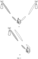
- FIG. 4 shows a PHR reporting manner by using a plurality of antenna panels according to an embodiment of this application.
- the terminal device may perform repeated sending by using different antenna panels, and repetition modes include a cyclic repetition (for example, (a) in FIG. 4 ) and a sequential repetition (for example, (b) in FIG. 4 ).
- the cyclic repetition may mean that the two antenna panels sequentially send two PHRs, and sending is repeated according to a sequential sending rule.
- the sequential repetition may mean that the two PHRs are sent based on an order, that is, a first PHR is repeatedly sent, and then a second PHR is repeatedly sent; or two antenna panels send PHRs based on an order, that is, the antenna panel 1 (which is also referred to as a first antenna panel) repeatedly send PHRs, and then the antenna panel 2 (which is also referred to as a second antenna panel) repeatedly send PHRs.
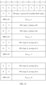
- FIG. 5 shows possible types of two PHRs when the terminal device simultaneously reports the two PHRs by using two antenna panels.
- a type of the PHR sent by using the antenna panel 1 may be determined based on the foregoing method (for detailed content, refer to the related standard).
- the PHR sent by using the antenna panel 1 is an actual PHR
- the PUSCH corresponding to the antenna panel 2 and the PUSCH corresponding to the antenna panel 1 are in a same slot
- the PHR sent by using the antenna panel 2 is an actual PHR.
- the PHR sent by using the antenna panel 1 is a virtual PHR, or the PUSCH corresponding to the antenna panel 2 and the PUSCH corresponding to the antenna panel 1 are not in a same slot
- the PHR sent by using the antenna panel 2 is a virtual PHR.
- the following uses an example to describe a method for determining a type of a PHR in an antenna panel-based PHR reporting process provided in this application.
- a PHR when a PHR is transmitted on a single channel, if two antenna panels are antenna panels for simultaneous transmitting (for example, the two antenna panels simultaneously send PHRs), and a difference between path losses (path losses) of the two antenna panels in information transmission is less than or equal to a first threshold, one PHR may be reported, where the PHR may be a PHR of the antenna panel 1 or a PHR of the antenna panel 2. If the difference between the path losses of the two antenna panels in information transmission is greater than the first threshold, two PHRs may be reported: the PHR of the antenna panel 1 and the PHR of the antenna panel 2.
- Simultaneous transmitting or simultaneous receiving of the antenna panels may be understood as simultaneous transmitting or simultaneous receiving of a plurality of antenna panels, or that the terminal device has a capability of simultaneous transmitting or simultaneous receiving by a plurality of antenna panels. It may also be understood that data or reference signals are simultaneously transmitted or received by using a plurality of antenna panels, or the terminal device simultaneously performs measurement by using a plurality of antenna panels.
- the terminal device may determine, based on a triggered object of a PHR reporting event, to report one or two PHRs. Specifically, if a PHR reporting trigger event triggers reporting of the antenna panel, two PHRs may be reported. The two PHRs may be the PHR of the antenna panel 1 and the PHR of the antenna panel 2. If the PHR reporting trigger event triggers reporting of the terminal device, one PHR may be reported, where the PHR may be a PHR of the terminal device.
- the two PHRs when two PHRs are transmitted on a single channel, if two antenna panels corresponding to the two PHRs are two antenna panels for simultaneous transmitting, the two PHRs are of a same type, that is, both are actual PHRs or both are virtual PHRs. Specifically, whether the two PHRs are actual PHRs or virtual PHRs may be determined based on related content in the embodiment shown in FIG. 3 .
- a type of the reported PHR may be determined in the following manner.
- the terminal device may determine a quantity and types of reported PHRs based on a triggered object of a PHR reporting event.
- the quantity and types of reported PHRs may be determined based on related content in the embodiment shown in FIG. 3 .
- the terminal device may determine the quantity and types of reported PHRs based on the triggered object of the PHR reporting event and the reporting manner.
- the two antenna panels each report two PHRs.
- a PHR corresponding to a triggered antenna panel is an actual PHR
- a PHR corresponding to an antenna panel that is not triggered is a virtual PHR.
- the two antenna panels each report two actual PHRs.
- the triggered antenna panel reports an actual PHR corresponding to the antenna panel, and the other antenna panel that is not triggered does not perform reporting.
- the two antenna panels each report one actual PHR, that is, the antenna panel 1 reports the PHR corresponding to the antenna panel 1, and the antenna panel 2 reports the PHR corresponding to the antenna panel 2.
- the calculated power of the antenna panel may also be referred to as a transmit power associated with the antenna panel.
- the calculated power of the antenna panel is related to a maximum transmit power of the terminal device.
- P O_PUSCH, b,f ,c ( i ) may be determined based on an access manner of the terminal device and a PUSCH transmission configuration manner, 10 log 10 2 ⁇ ⁇ M RB , b , f , c PUSCH i indicates a value of a bandwidth of a PUSCH resource, ⁇ b,f ,c ( j ) ⁇ PL b,f ,c ( q d ) indicates a value of a downlink path loss, ⁇ TF ,b,f ,c ( i ) indicates a value of an uplink bandwidth part of a carrier and a modulation and coding scheme of a serving cell, and f b,f,c ( i,l ) indicates a value of a PUSCH power control adjustment state.
- the parameters in the foregoing formula may be calculated based on a power control parameter for actually sending the PUSCH.
- a power control parameter for actually sending the PUSCH For content such as detailed meanings of the parameters, refer to a related standard.
- the calculated power of the antenna panel may also be referred to as a transmit power associated with the antenna panel.
- the calculated power of the antenna panel is related to a maximum transmit power of the terminal device.
- P O_PUSCH ,b,f ,c ( j ) may be determined based on an access manner of the terminal device and a PUSCH transmission configuration manner, ⁇ b,f ,c ( j ) ⁇ PL b,f ,c ( q d ) indicates a value of a downlink path loss, and f b,f ,c ( i,l ) indicates a value of a PUSCH power control adjustment state.
- the parameters in the foregoing formula may be calculated based on a predefined value.
- the calculated power of the antenna panel may also be referred to as a transmit power associated with the antenna panel.
- the calculated power of the antenna panel is related to a maximum transmit power of the terminal device.
- P O_SRS, b , f ,c ( q s ) indicates a value related to an active uplink bandwidth part
- 10log 10 (2 ⁇ ⁇ M SRS, b , f ,c ( i )) indicates a value of a bandwidth of an SRS
- ⁇ SRS, f ,c ( q s ) ⁇ PL b,f ,c ( q d ) indicates a value of a downlink path loss
- h b,f ,c ( i ) indicates a value of a transmission power control instruction value.
- the parameters in the foregoing formula may be calculated based on a power control parameter for actually sending the SRS.
- a power control parameter for actually sending the SRS For content such as detailed meanings of the parameters, refer to a related standard.
- the calculated power of the antenna panel may also be referred to as a transmit power associated with the antenna panel.
- the calculated power of the antenna panel is related to a maximum transmit power of the terminal device.
- P O _ SRS ,b,f ,c ( q s ) indicates a value related to an active uplink bandwidth part
- ⁇ SRS, f ,c,s ( q s ) ⁇ PL b , f ,c ( q d ) indicates a value of a downlink path loss
- h b,f ,c ( i ) indicates a value of a transmission power control instruction value.
- the parameters in the foregoing formula may be calculated based on a predefined value.
- a terminal device including two antenna panels is used as an example.
- P 1 and P 2 indicate an actual calculated power of the first antenna panel and an actual calculated power of the second antenna panel.
- P 1 and P 2 indicate a virtual calculated power of the first antenna panel and a virtual calculated power of the second antenna panel.
- a transmit power of each antenna panel is related to information such as a maximum transmit power of the antenna panel and the maximum transmit power of the terminal device.
- the maximum transmit power of the antenna panel or the maximum transmit power of the terminal device may be determined based on configuration information, or may be obtained through calculation based on a related parameter, and may be a maximum power (for example, a maximum transmit power used for PHR calculation) of the antenna panel or the terminal device for performing a specific action, or may be a total power of the antenna panel or the terminal device.
- antenna panel-based PHR reporting may be PHR reporting implemented based on any information corresponding to an antenna panel, for example, based on a candidate value (candidate value), a candidate value set (candidate value set), a panel identifier (panel identifier, panel ID), an SRS resource (SRS resource), or an SRS resource set (resource set).
- the terminal device may include a plurality of antenna panels.
- the antenna panels include at least a first antenna panel and a second antenna panel.
- the terminal device may send a channel and/or a signal by using the first antenna panel and/or the second antenna panel.
- a transmit power of the first panel is a first transmit power
- a transmit power of the second antenna panel is a second transmit power.
- the first transmit power is determined based on a calculated power of the first antenna panel and one or more of the following: the maximum transmit power of the terminal device, a maximum transmit power of the first panel, or a maximum transmit power of the second antenna panel.
- the second transmit power is determined based on a calculated power of the second antenna panel and one or more of the following: the maximum transmit power of the terminal device, the maximum transmit power of the first panel, or the maximum transmit power of the second antenna panel.
- the channel or the signal may be a PUSCH, a PUCCH, a preamble (preamble), an SRS, or the like.
- That the channel is sent by using the antenna panel may also be understood as that content of the channel is sent by using the antenna panel, that is, a signal of the channel is sent by using the antenna panel.
- the first transmit power is the first calculated power
- the second transmit power is the second calculated power
- the calculated power may be a value obtained through calculation based on a plurality of parameters according to the foregoing formula.
- the terminal device may determine an actual transmit power of each antenna panel based on the maximum transmit power of the terminal device. For example, the terminal device may obtain the maximum transmit power P cmax of the terminal device, and calculate the calculated power P 1 of the first antenna panel and the calculated power P 2 of the second antenna panel according to the foregoing formula. If a sum of P 1 and P 2 is less than or equal to P cmax , that is, the sum of the calculated power of the first antenna panel and the calculated power of the second antenna panel does not exceed the maximum transmit power of the terminal device, the first antenna panel and the second antenna panel may perform transmission based on the calculated powers, that is, the actual transmit power of the first antenna panel is the calculated power P 1 , and the actual transmit power of the second antenna panel is the calculated power P 2 .
- a sum of the calculated power of the first antenna panel and the calculated power of the second antenna panel is greater than the maximum transmit power of the terminal device, a sum of the first transmit power and the second transmit power is equal to the maximum transmit power of the terminal device.
- the terminal device may send a channel or a signal by using the antenna panels at a full power.
- the terminal device may obtain the maximum transmit power P cmax of the terminal device, and calculate the calculated power P 1 of the first antenna panel and the calculated power P 2 of the second antenna panel according to the foregoing formula. If a sum of P 1 and P 2 is greater than P cmax , a sum of the actual transmit power P 1a of the first antenna panel and the actual transmit power P 2a of the second antenna panel may be P cmax .
- the first transmit power is directly proportional to the first calculated power
- the second transmit power is directly proportional to the second calculated power
- P 1a is 0.8 times P 1
- P 2a is 0.7 times P 2
- a sum of 0.8 times P 1 and 0.7 times P 2 is P cmax .
- a ratio of the first transmit power to the second transmit power is equal to a ratio of the first calculated power to the second calculated power.
- P 1 : P 2 P 1a : P 2a
- P 1a + P 2a P cmax .
- the first transmit power is directly proportional to the maximum transmit power of the terminal device
- the second transmit power is directly proportional to the maximum transmit power of the terminal device
- P 1a may be 0.5 times P cmax
- P 2a may be 0.5 times P cmax
- P 1a may be 0.6 times P cmax
- P 2a may be 0.4 times P cmax .
- the first transmit power is the first calculated power or the maximum transmit power of the terminal device
- the second transmit power is the second calculated power or the maximum transmit power of the terminal device.
- P 1a may be P 1
- P 2a may be P cmax - P 1
- P 1a is P cmax
- P 2a is 0.
- P 2a may be P 2
- P 1a may be P cmax - P 2
- P 2a is P cmax
- P 1a is 0.
- a sum of the calculated power of the first antenna panel and the calculated power of the second antenna panel is greater than the maximum transmit power of the terminal device, a sum of the first transmit power and the second transmit power is less than the maximum transmit power of the terminal device.
- the terminal device may obtain the maximum transmit power P cmax of the terminal device, and calculate the calculated power P 1 of the first antenna panel and the calculated power P 2 of the second antenna panel according to the foregoing formula. If a sum of P 1 and P 2 is greater than P cmax , a sum of the actual transmit power P 1a of the first antenna panel and the actual transmit power P 2a of the second antenna panel may be less than P cmax .
- the first transmit power is directly proportional to the first calculated power
- the second transmit power is directly proportional to the second calculated power
- P 1a is 0.6 times P 1
- P 2a is 0.4 times P 2
- a sum of 0.6 times P 1 and 0.4 times P 2 is less than P cmax .
- P 1a is 0.9 times P 1
- P 2a is 0.
- the first transmit power is directly proportional to the maximum transmit power of the terminal device
- the second transmit power is directly proportional to the maximum transmit power of the terminal device
- P 1a may be 0.4 times P cmax
- P 2a may be 0.4 times P cmax
- P 1a may be 0.6 times P cmax
- P 2a may be 0.1 times P cmax
- P 1a may be 0, and P 2a may be 0.7 times P cmax .
- neither the first transmit power nor the second transmit power is 0.
- the terminal device may simultaneously transmit data by using the two antenna panels, to help reduce a vacancy rate of antenna panels and improve actual utilization of the plurality of antenna panels.
- the first transmit power is the first calculated power, and the second transmit power is greater than or equal to 0; or the second transmit power is the second calculated power, and the first transmit power is greater than or equal to 0.
- P 1a may be P 1
- P 2a may range from 0 to P cmax - P 1a .
- P 2a may be P 2
- P 1a may range from 0 to P cmax - P 2a .
- the actual transmit power of the first antenna panel and the actual transmit power of the second antenna panel are determined based on the relationship that the sum of the actual transmit power of the first antenna panel and the actual transmit power of the second antenna panel is less than the maximum transmit power of the terminal device, it may be further determined, based on the maximum transmit power of the first antenna panel and the maximum transmit power of the second antenna panel, that the actual transmit power of the first antenna panel is less than or equal to the maximum transmit power of the first antenna panel, and the actual transmit power of the second antenna panel is less than or equal to the actual transmit power of the second antenna panel.
- the maximum transmit power of the first antenna panel is P 1a and the actual transmit power of the second antenna panel is P 2a
- the maximum transmit power of the first antenna panel is P 1max
- the maximum transmit power of the second antenna panel is P 2max .
- the first antenna panel may perform data transmission based on P 1a .
- the first antenna panel may transmit data at a power not greater than P 1max .
- the first antenna panel may transmit data based on P 2a .
- P 2max is greater than or equal to P 2a
- the first antenna panel may transmit data at a power not greater than P 2max .
- the first transmit power and the second transmit power are further determined based on one or more of the following information: a channel priority, channel content, or a channel periodicity.
- an order or a priority of allocating powers to the plurality of antenna panels may be determined based on factors such as a priority of a channel corresponding to an antenna panel, channel content, and a channel periodicity.
- the first antenna panel corresponds to a PUCCH
- the second antenna panel corresponds to a PUSCH. It is assumed that a priority of the PUCCH is higher than that of the PUSCH, the terminal device may preferentially allocate a transmission power to the first antenna panel. For example, the actual transmit power of the first antenna panel is set to 0.8 times P cmax , and the actual transmit power of the second antenna panel is set to 0.1 times P cmax .
- a channel transmitted by using the first antenna panel is an aperiodic channel
- a channel transmitted by using the second antenna panel is a semi-persistent channel or a periodic channel.
- the terminal device may preferentially allocate a transmission power to the first antenna panel.
- the actual transmit power of the first antenna panel is set to P cmax
- the actual transmit power of the second antenna panel is set to 0.
- channel content transmitted by using the first antenna panel is a hybrid automatic repeat request-acknowledgment (hybrid automatic repeat request-acknowledgment, HARQ-ACK) or an uplink scheduling request (scheduling request, SR), and channel content transmitted by using the second antenna panel is CSI.
- HARQ-ACK hybrid automatic repeat request-acknowledgment
- SR uplink scheduling request
- the terminal device may preferentially allocate a transmission power to the first antenna panel. For example, the actual transmit power of the first antenna panel is set to 0.7 times P cmax , and the actual transmit power of the second antenna panel is set to 0.3 times P cmax .
- channel content transmitted by using the first antenna panel is a DG
- channel content transmitted by using the second antenna panel is a CG
- the terminal device may preferentially allocate a transmission power to the first antenna panel.
- the actual transmit power of the first antenna panel is set to 0.9 times P cmax
- the actual transmit power of the second antenna panel is set to 0.1 times P cmax .
- the terminal device may allocate a power to each of the plurality of antenna panels in the following priority order:
- an order relationship between priorities of the different channels, content of the different channels, and periods of the different channels may be determined by the terminal device based on pre-configured information.
- the PHR may be reported via a media access control control element (media access control control element, MAC-CE), and a reporting format of the PHR includes a single-CC format and a multi-CC format.
- media access control control element media access control control element, MAC-CE
- the terminal device may report a PHR of one antenna panel at a time, or may report PHRs of two antenna panels at a time, or the terminal device may report PHRs of more antenna panels at a time.
- the terminal device may report one or more PHRs by using one antenna panel, or the terminal device may jointly report or separately report a plurality of PHRs by using the plurality of antenna panels.
- FIG. 8 shows a MAC-CE in a single CC format when a terminal device reports a PHR by using one antenna panel.
- P CMAX,f,c This field indicates the maximum transmit power of the terminal for calculating the PH.
- a mapping relationship between this field and the maximum transmit power that can be implemented is shown in Table 2.
- Table 2 P CMAX,f,c levels and bit code mapping table P CMAX,f,c Nominal UE transmit power level 0 PCMAX_C_00 1 PCMAX_C_01 2 PCMAX_C_02 ... ... 61 PCMAX_C_61 62 PCMAX_C_62 63 PCMAX_C_63
- MPE If an MPE reporting value is configured (that is, mpe-Reporting-FR2 is configured), the MPE value is reported. If an MPE reporting value is not configured (that is, mpe-Reporting-FR2 is not configured), or operates on an FR1 frequency band, or a P field is set to 0, this field is a reserved field. Details may be shown in Table 3. Table 3 P-MPR level and bit code mapping table MPE Measured P-MPR value 0 P-MPR_00 1 P-MPR_01 2 P-MPR_02 3 P-MPR_03
- FIG. 9 and FIG. 10 show a MAC-CE in a multi-CC format when the terminal device reports a PHR by using one antenna panel.
- FIG. 9 shows a configured reporting format of a multi-CC PHR MAC-CE with an index of a serving cell that is less than 8
- FIG. 10 shows a configured reporting format of a multi-CC PHR MAC-CE with an index of a serving cell that is greater than or equal to 8.
- FIG. 11 shows a MAC-CE in a single CC format when the terminal device sends two PHRs by using two antenna panels.
- FIG. 12 and FIG. 13 show a MAC-CE in a multi-CC format when the terminal device sends, by using two antenna panels, two PHRs corresponding to the two antenna panels.
- FIG. 12 shows a configured reporting format of a multi-CC PHR MAC-CE with an index of a serving cell that is less than 8
- FIG. 13 shows a configured reporting format of a multi-CC PHR MAC-CE with an index of a serving cell that is greater than or equal to 8.
- periodicPHR-Timer (periodicPHR-Timer) is started.
- the following steps continue to be performed:
- a value of the type 1 PH or the type 3 PH of the activated cell is obtained at a physical layer; or if this MAC entity has uplink resources allocated for transmission on this activated cell or if another MAC entity has uplink resources allocated for transmission on this activated cell and phr-ModeOtherCG is set to real, a value for a corresponding P CMAX,f,c field is obtained from the physical layer, or a value for a MPE field (when mpe-Reporting-FR2 is configured
- phr-Type2OtherCell with a value true is configured, when another MAC entity is an E-UTRA MAC entity, a value of the type 2 PH for a special cell (special cell, SpCell) is obtained, or a value for a P CMAX,f,c field for the SpCell (when phr-ModeOtherCG is set to real).
- a multiplexing and assembly procedure is instructed to transmit a multiple entry PHR MAC-CE.
- a single entry PHR format is used, a value of a type 1 PH is obtained from the physical layer, and a value for a P CMAX,f,c field is obtained. If mpe-Reporting-FR2 is configured, a value for an MPE field is obtained from the physical layer Alternatively, a multiplexing and assembly procedure is instructed to transmit a single entry PHR MAC-CE.
- this PHR report is an MPE P-MPR report
- mpe-ProhibitTimer is started or restarted, or triggered MPE P-MPR reporting for serving cells included in the PHR MAC-CE is canceled.
- phr-PeriodicTimer is started or restarted, or phr-ProhibitTimer is started or restarted, or all triggered PHRs are canceled.
- FIG. 14 shows an information transmission method according to an embodiment of this application.
- a terminal device may include a plurality of antenna panels, and the plurality of antenna panels may include a first antenna panel.
- the terminal device sends a first message to a network device, and correspondingly, the network device receives the first message.
- the first message indicates a power headroom of the first antenna panel.
- the first message further indicates one or more of the following: a maximum transmit power of the first antenna panel, a power headroom of a second antenna panel, a maximum transmit power of the second antenna panel, a power headroom of the terminal device, or a maximum transmit power of the terminal device.
- the power headroom of the first antenna panel is determined based on a first calculated power and at least one of the following: the maximum transmit power of the first antenna panel or the maximum transmit power of the terminal device.
- the first calculated power is related to the maximum transmit power of the terminal device.
- the terminal device sends a second message to the network device, and correspondingly, the network device receives the second message.
- the second message indicates the power headroom of the second antenna panel.
- the second message further indicates one or more of the following: the power headroom of the first antenna panel, the maximum transmit power of the first antenna panel, the maximum transmit power of the second antenna panel, the power headroom of the terminal device, or the maximum transmit power of the terminal device.
- the power headroom of the second antenna panel is determined based on a second calculated power and at least one of the following: the maximum transmit power of the second antenna panel or the maximum transmit power of the terminal device.
- the second calculated power is related to the maximum transmit power of the terminal device.
- the terminal device sends a third message to the network device, and correspondingly, the network device receives the third message.
- the third message indicates the power headroom of the terminal device and/or the maximum transmit power of the terminal device.
- One or more of the power headroom of the first antenna panel, the power headroom of the second antenna panel, or the power headroom of the terminal device are used to determine a transmission power of the first antenna panel and/or a transmission power of the second antenna panel.
- the power headroom of the terminal device is determined based on the maximum transmit power of the terminal device and one or more of the following: the maximum transmit power of the first antenna panel, the maximum transmit power of the second antenna panel, a first transmit power, and a second transmit power.
- the first transmit power is a transmit power associated with the first antenna panel
- the second transmit power is a transmit power associated with the second antenna panel.
- a type of the first message and a type of the second message are determined based on one or more of the following information: whether the first message and the second message are transmitted on a same channel; whether to trigger the first antenna panel and/or the second antenna panel to send the first message and/or the second message; or a manner of sending the first message and the second message.
- the power headroom of the first antenna panel and/or the power headroom of the second antenna panel are/is further determined based on one or more of the following: a channel priority, channel content, or a channel periodicity.
- the first antenna panel and the second antenna panel are two antenna panels for simultaneous transmitting and/or simultaneous receiving.
- Simultaneous transmitting or simultaneous receiving of the antenna panels may be understood as simultaneous transmitting or simultaneous receiving of a plurality of antenna panels, or that the terminal device has a capability of simultaneous transmitting or simultaneous receiving by a plurality of antenna panels. It may also be understood that data or reference signals are simultaneously transmitted or received by using a plurality of antenna panels, or the terminal device simultaneously performs measurement by using a plurality of antenna panels.
- the network device may determine a working status of the terminal device and working statuses of the different antenna panels based on the received message.
- the terminal device performs information transmission by using the first antenna panel and the second antenna panel, and the terminal device reports the power headroom PH 1 of the first antenna panel, the power headroom PH 2 of the second antenna panel, and the power headroom PH c of the terminal device to the network device based on one or more of the first message, the second message, or the third message.
- the network device may determine whether the first antenna panel reaches the maximum transmit power and whether the second antenna panel reaches the maximum transmit power.
- the network device determines that no more additional power can be scheduled from the terminal device for information transmission.
- the network device may further determine working statuses of the two antenna panels. If the power headroom of the first antenna panel is greater than 0, and the power headroom of the second antenna panel is less than or equal to 0, the network device may schedule a power of the first antenna panel and allocate the power to the second antenna panel.
- the calculated power of the first antenna panel is 20 dBm
- the calculated power of the second antenna panel is 20 dBm
- the maximum transmit power of the first antenna panel is 23 dBm
- the maximum transmit power of the second antenna panel is 23 dBm
- the maximum transmit power of the terminal device is 23 dBm.
- the terminal device may report the power headroom 0 dBm of the terminal device, the power headroom 3 dBm of the first antenna panel, and the power headroom 3 dBm of the second antenna panel.
- the network device may determine that there is no remaining power of the terminal device, but there is still a remaining power of each antenna panel. Therefore, power sharing may be performed on the plurality of antenna panels.
- the calculated power of the first antenna panel is 20 dBm
- the calculated power of the second antenna panel is 20 dBm
- the maximum transmit power of the first antenna panel is 23 dBm
- the maximum transmit power of the second antenna panel is 23 dBm
- the maximum transmit power of the terminal device is 26 dBm.
- the terminal device may report the power headroom 3 dBm of the first antenna panel and the power headroom 3 dBm of the second antenna panel.
- the network device may determine that there is still a remaining power of each antenna panel. Therefore, power sharing may be performed on the plurality of antenna panels.
- the configuration information is used to schedule the plurality of antenna panels in the terminal device to perform data transmission.
- the configuration information is further used to determine transmission powers of the plurality of antenna panels in the terminal device.
- the network device that obtains information such as the power headroom of the antenna panel and the power headroom of the terminal device determines the working statuses of the antenna panel and the terminal device, and may send the configuration information to the terminal device.
- the configuration information may be used to request to reallocate the power of the antenna panel, may be used to schedule the plurality of antenna panels in the terminal device, or the like.
- the network device may determine, based on received information about the power headrooms of the antenna panels, that the terminal device currently has a power that can be allocated or scheduled. In other words, if the terminal device reports only the power headroom of the antenna panel, it may implicitly indicate that the power headroom of the terminal device is greater than 0, or implicitly indicate that the terminal device has a power that can be allocated.
- embodiments of this application further provide a communication apparatus.
- the communication apparatus may have a function of the terminal device or the network device in the foregoing method embodiments, and may be configured to perform steps performed by the terminal device or the network device in the foregoing method embodiments.
- the function may be implemented by hardware, or may be implemented by software or by hardware executing corresponding software.
- the hardware or the software includes one or more modules corresponding to the foregoing function.
- a communication apparatus 1500 shown in FIG. 15 may be used as the terminal device used in the foregoing method embodiments, and perform the steps performed by the terminal device in the foregoing method embodiments.
- the communication apparatus 1500 may include a communication module 1510 and a processing module 1520.
- the communication module 1510 is coupled to the processing module 1520.
- the communication module 1510 may be configured to support the communication apparatus 1500 in performing communication, for example, performing a sending and/or receiving action performed by the terminal device in the foregoing embodiments.
- the processing module 1520 may be configured to support the communication apparatus 1500 in performing a processing action in the foregoing method embodiments, for example, performing the processing action performed by the terminal device in the foregoing embodiments.
- the communication apparatus 1500 shown in FIG. 15 may be used as the network device used in the foregoing method embodiments, and perform the steps performed by the network device in the foregoing method embodiments.
- the communication apparatus 1500 may include the communication module 1510 and the processing module 1520.
- the communication module 1510 is coupled to the processing module 1520.
- the communication module 1510 may be configured to support the communication apparatus 1500 in performing communication, for example, performing a sending and/or receiving action performed by the network device in the foregoing embodiments.
- the processing module 1520 may be configured to support the communication apparatus 1500 in performing a processing action in the foregoing method embodiments, for example, performing the processing action performed by the network device in the foregoing embodiments.
- the communication apparatus 1500 may further include a storage module 1530, configured to store program code and data of the communication apparatus 1500.
- FIG. 16 is a block diagram of a communication device 1600 according to an embodiment of this application.
- the communication device 1600 includes at least one processor 1610 and a transceiver 1620.
- the processor 1610 is coupled to a memory, and is configured to execute instructions stored in the memory, to control the transceiver 1620 to send a signal and/or receive a signal.
- the communication device 1600 further includes a memory 1630, configured to store instructions.
- the processor 1610 and the memory 1630 may be integrated into a processing apparatus.
- the processor 1610 is configured to execute program code stored in the memory 1630, to implement the foregoing functions.
- the memory 1630 may alternatively be integrated into the processor 1610 or independent of the processor 1610.
- the transceiver 1620 may include a receiver (which is also referred to as a receiving machine) and a transmitter (which is also referred to as a transmitting machine).
- the transceiver 1620 may further include an antenna, and there may be one or more antennas.
- the transceiver 1620 may be a communication interface or an interface circuit.
- the chip When the communication device 1600 is a chip, the chip includes a transceiver unit and a processing unit.
- the transceiver unit may be an input/output circuit or a communication interface.
- the processing unit may be a processor, a microprocessor, or an integrated circuit integrated on the chip.
- steps in the foregoing method can be implemented by using a hardware integrated logical circuit in the processor, or by using instructions in a form of software.
- the steps of the method disclosed with reference to embodiments of this application may be directly performed by a hardware processor, or may be performed by using a combination of hardware in the processor and a software module.
- the software module may be located in a mature storage medium in the art, for example, a random access memory, a flash memory, a read-only memory, a programmable read-only memory, an electrically erasable programmable memory, or a register.
- the storage medium is located in the memory, and the processor reads information in the memory and completes the steps in the foregoing method in combination with hardware of the processor. To avoid repetition, details are not described herein again.
- An embodiment of this application further provides a computer-readable storage medium.
- the computer-readable storage medium stores computer instructions for implementing the method performed by the communication device in the foregoing method embodiments.
- the computer program when executed by a computer, the computer is enabled to implement the method performed by the communication device in the foregoing method embodiments.
- the processor mentioned in embodiments of this application may be a central processing unit (central processing unit, CPU), and may further be another general-purpose processor, a digital signal processor (digital signal processor, DSP), an application-specific integrated circuit (application-specific integrated circuit, ASIC), a field programmable gate array (field programmable gate array, FPGA) or another programmable logic device, a discrete gate or a transistor logic device, a discrete hardware component, or the like.
- the general-purpose processor may be a microprocessor, or the processor may be any conventional processor or the like.
- the memory mentioned in embodiments of this application may be a volatile memory and/or a non-volatile memory.
- the nonvolatile memory may be a read-only memory (read-only memory, ROM), a programmable read-only memory (programmable ROM, PROM), an erasable programmable read-only memory (erasable PROM, EPROM), an electrically erasable programmable read-only memory (electrically EPROM, EEPROM), or a flash memory.
- the volatile memory may be a random access memory (random access memory, RAM).
- the RAM may be used as an external cache.
- the RAM may include the following plurality of forms: a static random access memory (static RAM, SRAM), a dynamic random access memory (dynamic RAM, DRAM), a synchronous dynamic random access memory (synchronous DRAM, SDRAM), a double data rate synchronous dynamic random access memory (double data rate SDRAM, DDR SDRAM), an enhanced synchronous dynamic random access memory (enhanced SDRAM, ESDRAM), a synchlink dynamic random access memory (synchlink DRAM, SLDRAM), and a direct rambus random access memory (direct rambus RAM, DR RAM).
- static random access memory static random access memory
- DRAM dynamic random access memory
- DRAM synchronous dynamic random access memory
- SDRAM double data rate synchronous dynamic random access memory
- double data rate SDRAM double data rate SDRAM
- ESDRAM enhanced synchronous dynamic random access memory
- synchlink dynamic random access memory synchlink dynamic random access memory
- direct rambus RAM direct rambus RAM, DR RAM
- processor when the processor is a general-purpose processor, a DSP, an ASIC, an FPGA or another programmable logic device, a discrete gate or a transistor logic device, or a discrete hardware component, a memory (storage module) may be integrated into the processor.
- memory described herein is intended to include, but is not limited to, these and any other appropriate type of memory.
- the disclosed system, apparatus, and method may be implemented in other manners.
- the described apparatus embodiments are merely examples.
- division into the units is merely logical function division.
- a plurality of units or components may be combined or integrated into another system, or some features may be ignored or not performed.
- the displayed or discussed mutual couplings or direct couplings or communication connections may be implemented through some interfaces.
- the indirect couplings or communication connections between the apparatuses or units may be implemented in electronic, mechanical, or other forms.
- the units described as separate parts may or may not be physically separate, and parts displayed as units may or may not be physical units, may be located in one position, or may be distributed on a plurality of network units. Some or all of the units may be selected based on actual requirements to achieve the objectives of the solutions of embodiments.
- functional units in embodiments of this application may be integrated into one processing unit, or each of the units may exist alone physically, or two or more units are integrated into one unit.
- the functions When the functions are implemented in the form of a software functional unit and sold or used as an independent product, the functions may be stored in a computer-readable storage medium. Based on such an understanding, the technical solutions of this application essentially, or the part contributing to the conventional technology, or some of the technical solutions may be implemented in a form of a software product.
- the software product is stored in a storage medium, and includes several instructions for indicating a computing device (which may be a personal computer, a server, or a network device) to perform all or a part of the steps of the methods described in embodiments of this application.
- the foregoing storage medium includes any medium that can store program code, for example, a USB flash drive, a removable hard disk, a read-only memory (read-only memory, ROM), a random access memory (random access memory, RAM), a magnetic disk, or an optical disc.
- a USB flash drive for example, a USB flash drive, a removable hard disk, a read-only memory (read-only memory, ROM), a random access memory (random access memory, RAM), a magnetic disk, or an optical disc.
Landscapes
- Engineering & Computer Science (AREA)
- Computer Networks & Wireless Communication (AREA)
- Signal Processing (AREA)
- Physics & Mathematics (AREA)
- Mathematical Physics (AREA)
- Mobile Radio Communication Systems (AREA)
Applications Claiming Priority (2)
| Application Number | Priority Date | Filing Date | Title |
|---|---|---|---|
| CN202210970373.6A CN117641557A (zh) | 2022-08-12 | 2022-08-12 | 传输信息的方法和装置 |
| PCT/CN2023/103839 WO2024032216A1 (fr) | 2022-08-12 | 2023-06-29 | Procédé de transmission d'informations, et appareil |
Publications (2)
| Publication Number | Publication Date |
|---|---|
| EP4557842A1 true EP4557842A1 (fr) | 2025-05-21 |
| EP4557842A4 EP4557842A4 (fr) | 2026-01-14 |
Family
ID=89850714
Family Applications (1)
| Application Number | Title | Priority Date | Filing Date |
|---|---|---|---|
| EP23851443.4A Pending EP4557842A4 (fr) | 2022-08-12 | 2023-06-29 | Procédé de transmission d'informations, et appareil |
Country Status (4)
| Country | Link |
|---|---|
| US (1) | US20250184925A1 (fr) |
| EP (1) | EP4557842A4 (fr) |
| CN (1) | CN117641557A (fr) |
| WO (1) | WO2024032216A1 (fr) |
Families Citing this family (1)
| Publication number | Priority date | Publication date | Assignee | Title |
|---|---|---|---|---|
| US20250063435A1 (en) * | 2023-08-17 | 2025-02-20 | Viavi Solutions Inc. | Electromagnetic field (emf) measurement with maximized network throughput |
Family Cites Families (8)
| Publication number | Priority date | Publication date | Assignee | Title |
|---|---|---|---|---|
| KR100705448B1 (ko) * | 2005-12-09 | 2007-04-09 | 한국전자통신연구원 | 다중 안테나로 구성된 ofdm에서 채널 정보 및 코드북을이용한 송신 전력 할당 방법 및 장치 |
| CN110224802B (zh) * | 2018-09-28 | 2021-05-04 | 华为技术有限公司 | 一种通信方法、装置、存储介质及处理装置 |
| WO2020168296A1 (fr) * | 2019-02-14 | 2020-08-20 | Hyoungsuk Jeon | Rapport de marge de puissance pour de multiples groupes d'antennes |
| CN111726135B (zh) * | 2019-03-22 | 2022-01-14 | 成都华为技术有限公司 | 通信方法和通信设备 |
| CN112350754B (zh) * | 2019-08-06 | 2022-03-29 | 成都华为技术有限公司 | 一种天线面板状态的通知方法、设备、芯片及存储介质 |
| CN113365336B (zh) * | 2020-03-06 | 2023-09-05 | 维沃移动通信有限公司 | 功率余量报告上报方法及终端 |
| CA3112971A1 (fr) * | 2020-03-18 | 2021-09-18 | Comcast Cable Communications, Llc | Detection et rapport d`exposition pour communication sans fil |
| WO2021212451A1 (fr) * | 2020-04-24 | 2021-10-28 | Qualcomm Incorporated | Division de puissance pour une transmission en liaison montante à l'aide de multiples panneaux d'antenne |
-
2022
- 2022-08-12 CN CN202210970373.6A patent/CN117641557A/zh active Pending
-
2023
- 2023-06-29 EP EP23851443.4A patent/EP4557842A4/fr active Pending
- 2023-06-29 WO PCT/CN2023/103839 patent/WO2024032216A1/fr not_active Ceased
-
2025
- 2025-02-11 US US19/050,275 patent/US20250184925A1/en active Pending
Also Published As
| Publication number | Publication date |
|---|---|
| CN117641557A (zh) | 2024-03-01 |
| WO2024032216A1 (fr) | 2024-02-15 |
| EP4557842A4 (fr) | 2026-01-14 |
| US20250184925A1 (en) | 2025-06-05 |
Similar Documents
| Publication | Publication Date | Title |
|---|---|---|
| US12309864B2 (en) | Resource allocation method, terminal, network device and computer storage medium | |
| EP4092921A1 (fr) | Procédé et appareil de détermination d'un paramètre d'envoi, procédé et appareil de détermination de puissance d'envoi, procédé et appareil de détermination de phr, et support de stockage | |
| EP4192105A1 (fr) | Procédé d'indication de forme d'onde, puce, et système | |
| EP3860230A1 (fr) | Procédé d'émission de signal, dispositif et système associés | |
| US11445450B2 (en) | Uplink data transmission method, terminal device, and base station | |
| US20190037502A1 (en) | Power control method and device | |
| US20240244533A1 (en) | Ul gap triggering | |
| US20240430810A1 (en) | Communication method and apparatus | |
| EP4462891A1 (fr) | Procédé, appareil et système de transmission de rapport de marge de puissance | |
| US20250150987A1 (en) | Medium access control (mac) control element (ce) design for multiple power management maximum power reduction (p-mpr) reporting | |
| WO2022067823A1 (fr) | Procédé et dispositif de commande de puissance de liaison montante | |
| US20240407038A1 (en) | Data transmission method and communication apparatus | |
| WO2023202530A1 (fr) | Procédé et appareil de détermination de puissance, puce et dispositif de module | |
| US20250184925A1 (en) | Information transmission method and apparatus | |
| US20240276526A1 (en) | Communication method and apparatus | |
| EP4708983A1 (fr) | Procédé, dispositif et système de communications | |
| EP4460114A1 (fr) | Procédé et appareil pour rapport de réserve de puissance | |
| US20240334349A1 (en) | Wireless communication method, terminal device and network device | |
| CN115707108A (zh) | 一种通信方法、装置及系统 | |
| US20240276517A1 (en) | Uplink transmission and uplink reception with multiple panels related methods and user equipment | |
| EP4665013A1 (fr) | Procédé de rapport de réserve de puissance, appareil de communication, terminal et dispositif réseau | |
| EP4593475A1 (fr) | Procédé de rapport d'informations d'indication de marge de puissance, dispositif électronique et support de stockage | |
| WO2024168874A1 (fr) | Procédé de partage de puissance pour transmission multi-panneau de liaison montante | |
| WO2024011515A1 (fr) | Utilisation de puissance dans un regroupement de porteuses pour des communications sans fil | |
| US20250119846A1 (en) | Method and apparatus for beam information reporting |
Legal Events
| Date | Code | Title | Description |
|---|---|---|---|
| STAA | Information on the status of an ep patent application or granted ep patent |
Free format text: STATUS: THE INTERNATIONAL PUBLICATION HAS BEEN MADE |
|
| PUAI | Public reference made under article 153(3) epc to a published international application that has entered the european phase |
Free format text: ORIGINAL CODE: 0009012 |
|
| STAA | Information on the status of an ep patent application or granted ep patent |
Free format text: STATUS: REQUEST FOR EXAMINATION WAS MADE |
|
| 17P | Request for examination filed |
Effective date: 20250217 |
|
| AK | Designated contracting states |
Kind code of ref document: A1 Designated state(s): AL AT BE BG CH CY CZ DE DK EE ES FI FR GB GR HR HU IE IS IT LI LT LU LV MC ME MK MT NL NO PL PT RO RS SE SI SK SM TR |
|
| REG | Reference to a national code |
Ref country code: DE Ref legal event code: R079 Free format text: PREVIOUS MAIN CLASS: H04W0052360000 Ipc: H04B0007060000 |
|
| RIC1 | Information provided on ipc code assigned before grant |
Ipc: H04B 7/06 20060101AFI20250924BHEP Ipc: H04B 7/0456 20170101ALI20250924BHEP Ipc: H04W 52/36 20090101ALI20250924BHEP Ipc: H04W 52/42 20090101ALI20250924BHEP |
|
| DAV | Request for validation of the european patent (deleted) | ||
| DAX | Request for extension of the european patent (deleted) | ||
| A4 | Supplementary search report drawn up and despatched |
Effective date: 20251212 |
|
| RIC1 | Information provided on ipc code assigned before grant |
Ipc: H04B 7/06 20060101AFI20251208BHEP Ipc: H04B 7/0456 20170101ALI20251208BHEP Ipc: H04W 52/36 20090101ALI20251208BHEP Ipc: H04W 52/42 20090101ALI20251208BHEP |