EP4559298A1 - Procédé de direction pour une machine agricole - Google Patents
Procédé de direction pour une machine agricole Download PDFInfo
- Publication number
- EP4559298A1 EP4559298A1 EP24208443.2A EP24208443A EP4559298A1 EP 4559298 A1 EP4559298 A1 EP 4559298A1 EP 24208443 A EP24208443 A EP 24208443A EP 4559298 A1 EP4559298 A1 EP 4559298A1
- Authority
- EP
- European Patent Office
- Prior art keywords
- agricultural machine
- steering
- towing vehicle
- lane
- determined
- Prior art date
- Legal status (The legal status is an assumption and is not a legal conclusion. Google has not performed a legal analysis and makes no representation as to the accuracy of the status listed.)
- Pending
Links
Images



Classifications
-
- A—HUMAN NECESSITIES
- A01—AGRICULTURE; FORESTRY; ANIMAL HUSBANDRY; HUNTING; TRAPPING; FISHING
- A01B—SOIL WORKING IN AGRICULTURE OR FORESTRY; PARTS, DETAILS, OR ACCESSORIES OF AGRICULTURAL MACHINES OR IMPLEMENTS, IN GENERAL
- A01B69/00—Steering of agricultural machines or implements; Guiding agricultural machines or implements on a desired track
- A01B69/007—Steering or guiding of agricultural vehicles, e.g. steering of the tractor to keep the plough in the furrow
- A01B69/008—Steering or guiding of agricultural vehicles, e.g. steering of the tractor to keep the plough in the furrow automatic
-
- A—HUMAN NECESSITIES
- A01—AGRICULTURE; FORESTRY; ANIMAL HUSBANDRY; HUNTING; TRAPPING; FISHING
- A01B—SOIL WORKING IN AGRICULTURE OR FORESTRY; PARTS, DETAILS, OR ACCESSORIES OF AGRICULTURAL MACHINES OR IMPLEMENTS, IN GENERAL
- A01B69/00—Steering of agricultural machines or implements; Guiding agricultural machines or implements on a desired track
- A01B69/003—Steering or guiding of machines or implements pushed or pulled by or mounted on agricultural vehicles such as tractors, e.g. by lateral shifting of the towing connection
- A01B69/004—Steering or guiding of machines or implements pushed or pulled by or mounted on agricultural vehicles such as tractors, e.g. by lateral shifting of the towing connection automatic
-
- B—PERFORMING OPERATIONS; TRANSPORTING
- B62—LAND VEHICLES FOR TRAVELLING OTHERWISE THAN ON RAILS
- B62D—MOTOR VEHICLES; TRAILERS
- B62D13/00—Steering specially adapted for trailers
- B62D13/005—Steering specially adapted for trailers operated from tractor steering system
-
- B—PERFORMING OPERATIONS; TRANSPORTING
- B62—LAND VEHICLES FOR TRAVELLING OTHERWISE THAN ON RAILS
- B62D—MOTOR VEHICLES; TRAILERS
- B62D13/00—Steering specially adapted for trailers
- B62D13/02—Steering specially adapted for trailers for centrally-pivoted axles
- B62D13/025—Steering specially adapted for trailers for centrally-pivoted axles the pivoted movement being initiated by the coupling means between tractor and trailer
-
- B—PERFORMING OPERATIONS; TRANSPORTING
- B62—LAND VEHICLES FOR TRAVELLING OTHERWISE THAN ON RAILS
- B62D—MOTOR VEHICLES; TRAILERS
- B62D13/00—Steering specially adapted for trailers
- B62D13/04—Steering specially adapted for trailers for individually-pivoted wheels
-
- B—PERFORMING OPERATIONS; TRANSPORTING
- B62—LAND VEHICLES FOR TRAVELLING OTHERWISE THAN ON RAILS
- B62D—MOTOR VEHICLES; TRAILERS
- B62D15/00—Steering not otherwise provided for
- B62D15/02—Steering position indicators ; Steering position determination; Steering aids
- B62D15/025—Active steering aids, e.g. helping the driver by actively influencing the steering system after environment evaluation
Definitions
- the present invention relates to a steering method for an agricultural machine according to the preamble of claim 1, an agricultural machine according to the preamble of claim 13, a tractor/trailer combination according to the preamble of claim 14 and a control device for an agricultural machine according to the preamble of claim 15.
- Agricultural machinery that is pulled by a tractor during field work, and self-propelled agricultural machinery that is controlled by a driver during field work have long been known. These machines can also be moved in the same way during transfer journeys or road journeys, i.e., on the way to or from the field, either pulled by the tractor or steered independently by the driver.
- the brakes can be powered and controlled by the towing vehicle. Where available, this also applies to steerable axles of the towed agricultural machinery.
- autonomous agricultural machinery is increasingly being used. These have their own drive and steering and carry out field work independently, without control commands from a driver. Since these vehicles cannot carry out a transfer journey on the road autonomously, they must be loaded onto a low-loader, for example, which is complex and increases the costs of the entire operation.
- the object of the invention is to optimise the steering of an agricultural machine attached to a towing vehicle during road travel.
- Agricultural machinery can also be referred to as an agricultural work machine. It can be a harvesting machine such as a forage harvester, a combine harvester, a baler, or a loader wagon. However, it could also be a tedder, a plough, a fertilizer spreader, a slurry tanker, for example. or the like.
- the agricultural machine is designed for field cultivation, for example, for plowing, fertilizing, mowing, tedding, harvesting crops, or the like. It can have at least one attachment that is coupled to a vehicle body as needed, whereby the vehicle body itself is not designed for any specific type of field cultivation. It is considered an agricultural machine within the meaning of the invention even if no attachment is coupled during road travel.
- the agricultural machine can also be a trailer that is towed by a tractor during field cultivation. In this case, it is also towed during road travel or transfer travel.
- the agricultural machine can also have its own drive system that drives it both during field cultivation and while traveling on the road.
- it can be designed as an autonomous vehicle that is designed to carry out field cultivation without control commands from a driver or operator.
- the agricultural machine it would also be conceivable for the agricultural machine to have a control station or a driver's cab and to be controlled by a driver as needed.
- automatic steering takes place, as explained below.
- the agricultural machine is attached to a towing vehicle during a road journey, which travels along a towing vehicle lane.
- road journey is not to be interpreted strictly here and also refers to journeys on unpaved roads. It is used synonymously with "transfer journey,” i.e., a journey to or from the site of use.
- the towing vehicle can itself be an agricultural machine, but it can also be another vehicle, for example, a truck.
- the towing vehicle is a motor vehicle with its own drive, but it could also be, for example, a trailer without its own drive, which is itself towed. It can be a vehicle steered by a driver or an autonomous vehicle.
- the towing vehicle travels along a route or lane, which is referred to here and below as the towing vehicle lane.
- the towing vehicle lane can depend on short-term steering actions by a driver or an autonomous steering system and is potentially subject to constant changes. It can therefore only be determined in predict the future to a limited extent.
- the agricultural machine is attached to the towing vehicle, which generally means that the towing vehicle drives ahead when moving forward and pulls the agricultural machine. When reversing, the agricultural machine is pushed by the towing vehicle.
- the agricultural machine is attached, which means it is mechanically connected to the towing vehicle, but not rigidly, rather it is movable.
- the connection between the towing vehicle and the agricultural machine has at least one degree of freedom.
- the agricultural machine does not necessarily travel along the towing vehicle's lane.
- the towing vehicle can actuate a braking system on the agricultural machine and/or supply the agricultural machine with energy.
- the agricultural machine could also use its own energy storage device and/or its own energy generator to provide energy in a mechanical, hydraulic, electrical or other form.
- a steering mode is determined for at least part of the road journey, based on a plurality of possible steering modes of the agricultural machine.
- a steering mode of the agricultural machine or a steering mode for the agricultural machine is determined.
- the steering mode determines how the agricultural machine is steered. It characterizes and determines the steering behavior of the agricultural machine.
- the steering mode can contain one or more steering parameters that are determined. Once determined, the steering mode remains in place for at least part of the road journey. This means that it applies for a certain period of time or a distance. These can be predetermined or variable. In the latter case, the determined steering mode remains in place until further notice.
- the determined steering mode is one of a plurality of possible steering modes of the agricultural machine and is selected from these. Overall, a different number of steering modes can be provided. If the respective steering mode can be described by a steering parameter that can be varied quasi-continuously, this would result in a virtually "infinite" number of possible steering modes. In practice, this number is limited to a finite, but potentially very large, value.
- the steering mode can be defined within a control unit that performs various functions related to the steering of the agricultural machine. This can advantageously be part of the agricultural machine, if necessary. However, it could also be located entirely or partially externally, for example, on the towing vehicle. It can also comprise several spatially separated components. Some functions of the control unit can be implemented in software. However, the determination of the steering mode within the control unit does not necessarily mean that the determination is made by the control unit.
- kinematic data describing the kinematics of the agricultural machine are determined based on sensory measurements.
- the kinematic data are determined based on sensory measurements, i.e., based on measurements taken using at least one sensor. Different sensors can be used, as explained below.
- the respective sensor can be arranged on the agricultural machine or integrated into it. In principle, it would also be conceivable for it to be an external sensor.
- the kinematic data is based on the sensory measurements, which includes the possibility that the kinematic data are identical to the measured values obtained by the measurement or are related to them in a trivial way.
- a calculation of the kinematic data can be carried out, which is based, for example, on a linking of measured values.
- the kinematic data describes the kinematics of the agricultural machine, i.e., the movement of the agricultural machine and/or its current spatial arrangement.
- the kinematic data can be determined by the aforementioned control unit.
- the control unit can receive wireless or wired measured values from the aforementioned at least one sensor, as well as additional data if necessary.
- the steering mode can also be set within the control unit.
- kinematic data are determined that describe a location, a speed, an acceleration, an orientation, an angular velocity and/or an angular acceleration.
- the respective kinematic data can all describe six of the quantities mentioned.
- These quantities are classically associated with the term kinematics and describe position, including orientation, as well as its change over time.
- Velocity and acceleration correspond to the first and second time derivatives of position.
- Each of these quantities is normally at least a two-dimensional quantity, and possibly also a three-dimensional quantity.
- a two-dimensional location can be characterized by an X and a Y coordinate, a three-dimensional location additionally by a Z coordinate.
- Angular velocity and angular acceleration correspond to the first and second time derivatives of orientation.
- Each of these quantities is at least one-dimensional, as long as an orientation etc. is considered within a plane.
- two- or three-dimensional orientations etc. can also be considered, which can be characterized by two or three angles.
- An example would be yaw angle, roll angle and pitch angle.
- lane information relating to the towing vehicle is determined, and the kinematic data is compared with this.
- the sensor measurement mentioned here is also carried out using at least one sensor. It is possible that at least one sensor and/or the measured values supplied by it are used in whole or in part both to determine the kinematic data and to determine the lane information.
- the lane information can also be determined by the control unit.
- the lane information relates to the towing vehicle and is therefore related to the towing vehicle's lane. However, it does not normally allow an exact description of the towing vehicle's lane, for example due to measurement errors, numerical inaccuracies, or other influences.
- the towing vehicle's lane can be characterized at least to a limited extent and approximately using the lane information.
- the determined kinematic data can be compared with this lane information.
- This comparison provides information about how the agricultural machine is positioned in relation to the tractor's lane and/or how it is moving in relation to the tractor's lane. Since the tractor's lane is generally not known exactly, The result of the comparison is inevitably also generally inaccurate. However, certain inaccuracies are acceptable and do not jeopardize the functional principle of the steering method according to the invention.
- steering commands are automatically determined for at least one steerable axle of the agricultural machine in order to steer the agricultural machine in accordance with the towing vehicle's lane.
- This process step can again be performed by the control unit.
- the agricultural machine can have one or more steerable axles. Each axle can be steered by at least one actuator, whereby the actual steering angle can be checked by an associated sensor.
- steering commands can be determined for all axles.
- the steering commands can be digital or analog signals. In any case, a steering command contains information about the respective steering angle of the steerable axle.
- the steering commands are determined in order to steer the agricultural machine in accordance with the towing vehicle's lane.
- Adapted to the towing vehicle's lane does not necessarily mean that the agricultural machine should follow the towing vehicle's lane as precisely as possible.
- the tractor's lane provides guidance for steering the agricultural machine.
- the steering commands are determined depending on the comparison result. This means that the comparison determines how the agricultural machine should be steered based on the determined kinematic data in order to achieve or maintain the intended adaptation to the tractor's lane (as far as it is known from the lane information).
- the determination also depends on the steering mode. This means that with the same lane information and the same kinematic data, different steering commands can be determined depending on the steering mode selected.
- the phrase "depending on” always means that there is at least a dependency on the specified variable. This always includes the possibility that there is also a dependency on at least one other variable. The phrase is therefore synonymous with "at least partially dependent on.”
- the agricultural machine is automatically steered based on the steering commands.
- This can also be done by the aforementioned control unit, which for this purpose can be connected wirelessly or wired to at least one steering actuator assigned to the at least one steerable axle.
- the advantage of the steering method according to the invention is that the specified steering mode enables automatic, demand-based steering of the agricultural machine. This can be adapted to different situations and/or different conditions by specifying a suitable steering mode. The steering behavior of the agricultural machine is thus not fixed, which could be suboptimal depending on the situation, but can be flexibly adjusted.
- the determined lane information corresponds to a calculated lane of the towing vehicle and the kinematic data corresponds to an actual lane of the agricultural machine, whereby the actual lane is compared with a target lane derived from the calculated lane depending on the currently defined steering mode, and the steering commands are determined depending on the result of the comparison.
- the calculated lane would ideally be identical to the towing vehicle lane or to a section thereof. In reality, there is generally a deviation from the towing vehicle lane, which is, however, acceptable within certain limits.
- the calculated lane can be determined up to the current point in time, but it can also be extrapolated for a certain time into the future.
- the latter can be particularly useful when reversing, where the agricultural machine is, in a sense, driving ahead of the towing vehicle.
- the actual lane is either part of the kinematic data that is determined or it is identical to this kinematic data.
- the actual track can also be determined up to the current point in time or extrapolated for a certain time into the future. In the latter case, For example, it can be assumed that the steering angle of at least one steerable axle is not changed compared to the current state.
- a target lane is determined for the agricultural machine, which is derived from the calculated lane.
- the target lane is derived from the calculated lane depending on the steering mode. This means that, depending on the steering mode, different target lanes can be derived from a specific calculated lane.
- By comparing the target lane with the actual lane it can be determined how the agricultural machine must be steered in order to move in the intended manner relative to the towing vehicle. Since the target lane is derived from the calculated lane, an (indirect) comparison with the calculated lane also takes place.
- the steering commands are then determined according to a possible deviation of the actual lane from the target lane.
- the steering mode is determined at least partially by user input. This means that a user decides which steering mode they currently consider appropriate and makes a corresponding input via a user interface.
- the user interface can be arranged on the agricultural machine.
- it should either be mobile, for example, arranged on a smartphone, tablet, or the like, or it should be arranged on the towing vehicle. It can be connected to the agricultural machine wirelessly and/or by wire, for example, to the aforementioned control unit.
- the steering mode can optionally be determined entirely by user input.
- the steering mode is determined at least partially automatically. Automatic means that the determination occurs without user intervention, and the user is thus excluded from selecting the steering mode.
- the automatic selection can be performed by the aforementioned control unit.
- the user can select a steering mode that then remains active until further notice. Under certain circumstances, the steering mode can then be automatically deactivated and a different steering mode selected instead.
- At least one redetermination of the steering mode is possible during road travel, in particular that the redetermination takes place during road travel.
- the steering mode is not determined for the entire road travel, but is redetermined during road travel, i.e., the steering mode is changed.
- the agricultural machine is connected to the towing vehicle, for example, via two coupling parts that can move relative to one another, one of which is rigidly connected to a vehicle body of the towing vehicle and the other rigidly to a vehicle body of the agricultural machine.
- a ball-and-socket coupling, a bolt coupling, or similar would be conceivable.
- the coupling would define the only joint that has one or more degrees of freedom.
- Another embodiment provides for the agricultural machine to be connected to the towing vehicle by a tension and pressure-transmitting drawbar, which is pivotally connected to both the towing vehicle and the agricultural machine.
- the drawbar can normally regarded as a rigid body, although it is possible that, for example, a slight elastic deformation of the drawbar may occur even during normal operation.
- the drawbar does not have any flexible areas or joints.
- the drawbar is manually or actuator-adjustable, for example, length-adjustable, in which case it could consist of two telescopically connected parts.
- the drawbar connects the towing vehicle to the agricultural machine and transfers a tractive force when driving forward and a compressive force from the towing vehicle to the agricultural machine when driving backward.
- the drawbar can be a separate component that is temporarily connected to the towing vehicle and agricultural machine for the purposes of road travel. It can also be permanently integrated into the towing vehicle or the agricultural machine, being pivotally connected to the body of the respective vehicle.
- the connection to the other vehicle can be established via a coupling (e.g. ball head coupling, etc.).
- the drawbar is pivotally connected on both sides, allowing at least one-dimensional pivoting, i.e., pivoting through a one-dimensional angle in the horizontal plane.
- at least limited pivoting in the vertical direction is usually also possible, so that it can be described as two-dimensional pivoting.
- the drawbar can be pivoted freely without restoring forces, but it is also possible for it to be connected to the towing vehicle and/or the agricultural machine via at least one spring element.
- a front axle of the agricultural machine is forcedly steered by the drawbar.
- a drawbar angle relative to the vehicle body of the agricultural machine determines a steering angle of the front axle.
- the corresponding forced steering can be implemented mechanically, which includes the possibility of a fluid-mechanical, for example, hydraulic or pneumatic coupling.
- a sensor-actuator coupling with at least one sensor that detects the drawbar angle and at least one actuator that adjusts the steering angle.
- the control unit of the actuator can be controlled in such a way that a certain value of the drawbar angle always corresponds to a certain value of the steering angle.
- the kinematic data are based on sensor measurements, for which different types of sensors can be used.
- the kinematic data and/or the lane information can be determined based on a measurement by at least one inertial sensor, an angle sensor for determining a drawbar angle, and/or a position sensor for determining a relative position of the towing vehicle to the agricultural machine.
- An inertial sensor is configured to determine inertial measurement values. These inertial measurement values correspond to at least one multidimensional acceleration, which includes both two-dimensional and three-dimensional accelerations. Apart from (translational) acceleration, an inertial sensor can also measure an angular acceleration, i.e., a temporal change in angular velocity.
- One or more inertial sensors can form an inertial measurement device.
- An inertial sensor can be arranged on the agricultural machine, on the drawbar, or on the towing vehicle. Of course, a plurality of inertial sensors can be provided, of which at least one is arranged on the agricultural machine and at least one on the drawbar and/or on the towing vehicle. At least in some embodiments, the inertial sensor can also be referred to as an IMU (inertial measurement unit).
- IMU inertial measurement unit
- An angle sensor can determine angle measurements that correspond to a drawbar angle, i.e., a relative angle of the drawbar to the body of the agricultural machine.
- an angle sensor can also be used to measure the relative angle between the drawbar and the towing vehicle.
- the term "relative angle” here includes both a one-dimensional angle measurement, which only determines how far the drawbar pivots horizontally to the left and right, and a two-dimensional angle measurement, which also measures how far the drawbar swings vertically upwards and downwards. Using the angle measurements from an angle sensor, the orientation of the drawbar relative to the towing vehicle and/or agricultural machinery can be determined with a high degree of precision.
- the position of a pivot point on the towing vehicle can be determined, for example, based on the position and orientation of the agricultural machinery, without having to resort to sensors on the towing vehicle. This information can be combined with other sensor data to track the position and/or movement of the towing vehicle as a whole.
- a position sensor can determine position measurements that correspond to the relative position of the towing vehicle to the agricultural machine.
- the position sensor can be designed, for example, as an ultrasonic sensor, radar sensor, or lidar sensor. It can also be designed as a camera (which can also be sensitive to infrared if necessary), whereby image recognition is used to identify certain structures on the towing vehicle and to determine the relative position based on their arrangement and apparent size within the camera image. For this purpose, information about the geometry of the towing vehicle must of course be stored on the corresponding evaluation unit. Different types of position sensors can also be combined.
- a position sensor can be used to compensate for any drift of an inertial measuring device. Alternatively or additionally, at least one position sensor could also be arranged on the towing vehicle.
- orientation sensor determines orientation measurements corresponding to the orientation of the agricultural machine and/or the towing vehicle relative to its surroundings. While an IMU, for example, can only provide information about a change in orientation, the orientation sensor can measure the orientation itself. This is a kind of "absolute" orientation information relative to the surroundings. In two dimensions, the orientation information corresponds, for example, to a compass direction. Such an orientation can be determined, for example, using a gyrocompass. This is a fundamentally reliable, but costly, solution. A more cost-effective, albeit potentially prone to failure, solution would be a magnetometer, which uses the Earth's magnetic field to measure orientation.
- Inertial measuring devices do not allow for direct position measurement or direct measurement of distance traveled. This information can only be determined by double (numerical) integration of the accelerations, which can generally lead to numerical errors that increase over time.
- This disadvantage can be compensated for by an additional sensor designed as a distance sensor, which determines distance measurements corresponding to a distance traveled by the agricultural machine and/or the towing vehicle.
- the distance sensor can also be referred to as an odometer, and the distance measurements can be referred to as odometry data. This normally involves measuring the number of revolutions of a wheel and multiplying this value by its known rolling circumference to determine the distance traveled.
- Such a distance sensor can be installed on the agricultural machine and/or the towing vehicle.
- the steering mode is determined depending on geometric data that describe a geometry of the towing vehicle, the drawbar, and/or the agricultural machine.
- geometric data can, for example, correspond to a length of the towing vehicle, the drawbar, and/or the agricultural machine, or to an axle spacing, a vehicle width, a track width, or other characteristics. It can also be information on the relative position of certain components of a vehicle, for example, the relative position of two sensors to one another.
- the geometric data can be more or less complex.
- a vehicle could be characterized solely by its length, width, and possibly height, but it could also contain a detailed three-dimensional model with a plurality of characteristic points of the vehicle, similar to a polygon approximation.
- the geometric data can be stored in the control unit, which performs the corresponding calculations, or it can be transmitted to the control unit from an external source.
- the position of a coupling on the towing vehicle can be determined from the drawbar angle of the drawbar if the length of the drawbar and its connection to the agricultural machine are known. It is possible for drawbars of different lengths to be used in combination with one and the same agricultural machine, or for a drawbar with an adjustable length to be used. Towing vehicles with different geometries could also be combined with an agricultural machine, which could be relevant, for example, to prevent a collision between the towing vehicle and the agricultural machine when cornering.
- the geometry data is preferably adapted at least partially automatically.
- changing geometry data of an adjustable drawbar is adapted. This means that if the dimensions of the drawbar change, the geometry data is also changed.
- the adaptation of the geometric data can occur automatically and/or according to user input. In the latter case, it could be provided that the user actually enters numerical values that characterize geometric dimensions. For greater user-friendliness, it can also be provided that the user makes a simple input that, for example, identifies a specific model whose geometric data is stored in a database and then used for the adaptation. With automatic adaptation, geometric data could be determined through sensory measurement, but this can be complex or even unreliable. On the other hand, automatic recognition of a specific model whose geometric data is stored or a transmission of geometric data as described above is advantageous.
- the agricultural machine has a vehicle body to which at least one attachment can be coupled, wherein geometric data of the agricultural machine are adapted as a function of at least one attachment coupled to the vehicle body and the steering mode is determined accordingly.
- the attachment can be designed for different types of field cultivation. For example, it can be connected to a lifting gear of the agricultural machine.
- an energy-transmitting connection can also be established, for example an electrical, hydraulic, or pneumatic connection.
- a wireless or wired data connection can also be established between the vehicle body and the attachment.
- the geometric data is adapted depending on whether an attachment is coupled to the vehicle body and/or which attachment is coupled. It is obvious that the overall dimensions of the agricultural machine depend significantly on whether an attachment is coupled and on its dimensions. This, in turn, influences which steering maneuvers the agricultural machine can perform easily or safely. Under certain circumstances, the current position of the attachment can also be taken into account if multiple positions are possible, which lead to significantly different overall dimensions of the agricultural machine.
- the drawbar length can also be adjusted depending on the attachment. If an attachment is attached, a longer drawbar length must be selected than without an attachment. This means that the drawbar's geometry can also be optionally adjusted depending on at least one attachment attached to the vehicle body.
- the automatic adaptation of the geometric data of the agricultural machine upon identification of an attachment is particularly preferred.
- the identification itself, however, can be carried out by user input. This means that the user could specify that a specific attachment is attached without having to know or specify its geometric data.
- the identification takes place automatically, for example through wireless or wired communication between the Attachment and the aforementioned control unit, which can be integrated into the vehicle body of the agricultural machine.
- Such automatic identification with automatic adaptation of the geometry data based on a plug-and-play principle, enables a particularly user-friendly application that largely eliminates human error.
- the drawbar geometry data can be adapted together with the agricultural machine geometry data, which can also be done automatically in this embodiment.
- a movement range of the towing vehicle is determined based on the lane information and geometric data of the towing vehicle, and the steering commands are determined depending on the movement range and the geometric data of the agricultural machine.
- the movement range is a two- or three-dimensional area through which the towing vehicle moves along the towing vehicle's lane. A two-dimensional view neglects the fact that the towing vehicle can have different horizontal dimensions depending on its height. The same applies to the agricultural machine. For many applications, a two-dimensional view is sufficient.
- the movement range is, in a sense, traversed by the towing vehicle, and it can be assumed that this area can also be traversed safely by the agricultural machine. This is used in the present embodiment to determine a suitable target route in combination with the geometric data of the agricultural machine.
- the target route corresponds to the calculated route, so that the agricultural machine ideally follows the route of the towing vehicle exactly.
- a steering mode could lead to problems, particularly with an agricultural machine that extends in the longitudinal or transverse direction.
- the agricultural machine could collide with stationary objects, for example an archway, a traffic sign, a house corner, etc., if it follows the route of the towing vehicle exactly. Therefore, a further development of the method provides that in at least In a steering mode, the movement area of the agricultural machine is limited at least on one side by the movement area of the towing vehicle. "One-sided" means either on the left or right side with respect to a transverse axis of the agricultural machine.
- the limitation is particularly relevant when cornering, one can also speak of an inside or outside curve limitation. In some cases, a bilateral limitation can be implemented. In other cases, only a one-sided limitation is possible.
- the movement area of the agricultural machine is limited on one side (for example, on the left or inside of the curve) by the movement area of the towing vehicle. This means that the movement area of the towing vehicle is determined using the calculated route, and then the target route is determined such that the movement area of the agricultural machine does not extend beyond the movement area of the towing vehicle on one side. For example, if there is a stationary object on the inside of the curve when cornering, the appropriate steering mode can ensure that the agricultural machine passes the object without collision, provided the towing vehicle has already done so.
- At least one steerable axle is locked depending on the steering mode. This means that in at least one steering mode, the steerable axle is locked, typically in a center or neutral position, while in at least one other steering mode, it is released for steering. This means that in the corresponding steering mode, the axle is deflected to the right or left as needed.
- the steering mode is determined depending on a certain travel speed and/or the presence of reversing. Both can be done based on user input. Preferably, it is automatic.
- the travel speed can be the speed of the towing vehicle and/or the agricultural machine itself, whereby the difference is usually negligible due to the coupling.
- a stronger and/or more sensitive steering of the agricultural machine is advantageous at low travel speeds, while at higher travel speeds, a less sensitive steering contributes to stabilization.
- at least one steerable axle can be locked depending on the driving speed.
- a steering mode in which the corresponding axle (for example the rear axle) is locked, whereby the agricultural machine and the vehicle combination as a whole can be stabilized.
- Several speed ranges can also be distinguished, for example a low, a medium, and a high speed range.
- a definition depending on the presence of reversing can also be advantageous. This can relate to reversing of the towing vehicle and/or the agricultural machine, which in turn almost always occur simultaneously due to the coupling.
- a different steering mode is defined for reversing than for forward travel. Different strategies are conceivable, whereby it can be particularly advantageous to lock a steerable axle when reversing, while it is released for steering when driving forward.
- the control device typically comprises a plurality of components that may be spatially separated from one another.
- it may comprise at least one sensor for performing the sensor measurement, as well as a control unit that may be spatially separated from the sensor.
- the control unit may be configured to enable the determination of the steering mode, determine the kinematic data, determine the lane information, and/or determine the steering commands.
- At least one steering actuator for steering at least one axle may also be considered part of the control device.
- the control device normally comprises a plurality of components that can be arranged spatially separate from one another. As described above, these can include at least one sensor, one control unit, and at least one actuator.
- the control device is preferably arranged at least partially on the agricultural machine and can, in particular, be arranged exclusively on the agricultural machine. However, it can also be arranged partially on the towing vehicle and/or—if present—on the drawbar. In such a case, parts of the control device can communicate with one another wirelessly or via a wired connection.
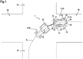
- Fig. 1 shows a plan view of a road intersection with a first road 50 and a second road 51.
- a combination 5 consisting of a towing vehicle 30 and an agricultural machine 10 coupled thereto via a drawbar 20 is about to turn from the first road 50 into the second road 51.
- the towing vehicle 30, which in this example is shown as a tractor, is traveling along a towing vehicle route Rz, which in Fig.1 , 3 and 5 as a long dashed line.
- the agricultural machine 10 has a front axle 14 and a rear axle 15, each of which is actively steerable by means of a front steering actuator 24 and a rear steering actuator 25 (shown in the block diagram in Fig. 2 ).
- the axles 14, 15 are arranged on a vehicle body 26.
- the drawbar 20 is pivotally connected to the towing vehicle 30 at a front pivot point 33 and pivotally connected to the agricultural machine 10 at a rear pivot point 21. It is pivotable at the aforementioned pivot points 21, 33. It transmits at least tensile and compressive forces parallel to its direction of travel. No steering commands are transmitted from the towing vehicle 30 to the agricultural machine 10.
- the control device 1 includes a control unit 22, which is arranged on the agricultural machine 10, and an inertial measuring device 11, which in this case has two spaced-apart inertial sensors 12.
- the inertial sensors 12 transmit inertial measured values Ma to the control unit 22, which correspond to a multi-dimensional acceleration and a multi-dimensional angular acceleration.
- the inertial measured values Ma received by the two inertial sensors 12 are, in principle, redundant with one another, which is used to perform a comparison and correct possible measurement errors.
- the agricultural machine 10 can have additional sensors 13, 16-19.
- an orientation sensor 13 which can be designed as a magnetometer, can be used to determine orientation measurement values Mo that correspond to an orientation, i.e., spatial alignment, of the agricultural machine 10.
- Position sensors 16 can determine position measurement values M P that correspond to a relative position of the towing vehicle 30 to the agricultural machine 10.
- These position sensors 16 could, for example, be designed as radar or lidar sensors.
- a Distance sensor 19 which can also be referred to as an odometer, determines distance measured values Ms, which correspond to a distance traveled by the agricultural machine 10.
- a speed sensor 18 is provided, which can measure the direction and magnitude of a speed of the agricultural machine 10 via a rotational speed of a wheel of the rear axle 15.
- an angle sensor 17 is arranged at the rear pivot point 21. This determines angle measured values Mw, which correspond to a drawbar angle of the drawbar 20 relative to the agricultural machine 10.
- the angle measured values Mw can also be transmitted wirelessly or wired to the control unit 22.
- Fig. 1 and 2 show a variety of sensors, which are not normally used together. However, a plurality of different types of sensors can serve to improve the precision of the control device 1.
- the agricultural machine 10 has a first user interface 23, and the towing vehicle 30 has a second user interface 31.
- a user input E can be made via each of the user interfaces 23, 31.
- Both user interfaces 23, 31 are connected wirelessly or by wire to the control unit 22.
- the control device 1 carries out a steering method according to the invention, which will now be described with reference to the flow chart in Fig. 5 and additionally with reference to Fig. 2 , 3 and 4 is explained.
- the control unit 22 is initialized, during which vehicle body geometry data G F of the vehicle body 26 of the agricultural machine 10, towing vehicle geometry data G Z of the towing vehicle 30, and drawbar geometry data G D of the drawbar 20 are loaded.
- the towing vehicle geometry data G Z can be transmitted by the towing vehicle 30 or, after identification of the towing vehicle 30, loaded from a database to which the control unit 22 has access.
- the vehicle body geometry data G F are initially used to determine agricultural machine geometry data G L of the agricultural machine 10.
- the geometry data G D , G F , G L , Gz can describe different aspects of the geometry, for example length, width, axle distance, track width, arrangement of the
- initial values A are determined, in particular the initial position and orientation of the agricultural machine 10, its speed, and angular velocity. The latter are normally zero, since initialization typically occurs at a standstill.
- the initial position of the agricultural machine 10 can, for example, be selected as the coordinate origin or initialized with another default value; likewise, its orientation can be initialized with an angle of 0° or another default value.
- the orientation of the drawbar 20 can be determined using the angle sensor 21.
- the position of the tractor 30 can be determined, at least with respect to the front articulation point 33, using the angle sensor 17 in combination with the geometric data of the drawbar 20.
- the position sensors 16 could also be used, which may also allow a direct determination of the orientation of the towing vehicle 30.
- step S110 it is checked whether an attachment 27 is coupled to the vehicle body 26, as shown schematically in Fig.4 shown. If so, the type of attachment 27 is identified in step S120 and attachment geometry data GA is automatically loaded in step S130. The identification can be carried out by wireless or wired communication between the attachment 27 and the control unit 22, wherein the attachment geometry data GA can also be transmitted.
- step S140 the agricultural machine geometry data GL are updated taking into account the attachment geometry data GA . If the agricultural machine 10 has a plurality of coupling positions (for example lifting gear) for attachments 27, several attachments 27 can be taken into account in steps S120 to S140. If no attachment 27 is coupled, the aforementioned steps are skipped.
- step S150 the speed sensor 18 determines the magnitude of the speed and the sign of the speed is used to determine whether reversing is taking place.
- step S160 a query is made as to whether a user input E has been made via one of the user interfaces 23, 31, which influences the steering mode L.
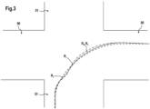
- the steering mode L is determined. This can be based at least partially on the user input E. For example, the user can select a steering mode in which the agricultural machine 10 follows the towing vehicle lane Rz of the towing vehicle 30 as precisely as possible, which will be described below with reference to Fig. 3 Alternatively, the user can select a steering mode in which a towing vehicle movement area BZ, through which the towing vehicle 30 moves, represents a one-sided limitation of an agricultural machine movement area BL, which is explained below with reference to Fig. 4 explained. He could also manually select that one of the axles 14, 15 should remain locked, or that both axles 14, 15 should be steered.
- the steering mode L can be set automatically.
- One possible criterion for automatic setting would be, for example, exceeding a limit value of the driving speed. Below this limit value, both axles 14, 15 could be steered for better maneuverability, while above the limit value the rear axle 15 is locked to stabilize the agricultural machine. The rear axle 15 could also be locked automatically when reversing.
- the steering mode L which can also be described by one or more steering parameters, can depend on the towing vehicle geometry data Gz of the towing vehicle 30, the drawbar geometry data G D of the drawbar 20 and the agricultural machine geometry data G L of the agricultural machine 10, as in Fig.2 is indicated. All of these geometric data can influence how the agricultural machine 10 is to be steered. In particular, the steering mode L can depend on the presence of an attachment 27 and its attachment geometry data GA .
- step S180 measured values M A , Mo, M P , Ms, Mw are measured using various sensors 12, 13, 16, 17, 19 and, as shown in the block diagram in Fig. 2 shown, sent to the control unit 22.
- a current speed and angular speed as well as a current position and orientation can be calculated, whereby the initial values A are required.
- Distance data Ms of the distance sensor 19 can also be included in order to specify the determined value for the current position, or orientation data Mo of the orientation sensor 13 in order to improve the precision of the determined orientation.
- an actual driving track R I of the agricultural machine 10 is calculated as part of the kinematic data, which in Fig. 3 shown as a dotted line.
- lane information relating to the towing vehicle 30 is determined.
- a lateral acceleration of the agricultural machine 10 can be used to infer a change in the direction of travel of the towing vehicle 30, both qualitatively and quantitatively.
- the precision can be improved if at least the angle sensor 17 and/or the position sensors 16 are also included, the measured values of which can be read in step S180.
- the position, orientation, speed and angular velocity of the towing vehicle 30 can be determined.
- a calculation lane RB can be determined, which in Fig.
- the calculated lane R B deviates partially from the actual towing vehicle lane R F. However, the deviation is minor and does not impair the basic function of the control device 1. In particular, when reversing, the calculated lane R B can also be extrapolated for the future.
- a target lane Rs for the agricultural machine 10 is determined in step S220. This is shown in the Fig.3 shown example is identical to the calculation lane R B , ie it is intended that the agricultural machine 10 follows exactly in the lane of the towing vehicle 30. Alternatively, it would also be conceivable that the target lane is determined in such a way that an agricultural machine movement area B L is limited on one side by the towing vehicle movement area Bz.
- a boundary is provided on the right-hand side in the direction of travel, so that the agricultural machine movement area B L , represented by a dotted line, is limited on the outside of the curve by the towing vehicle movement area Bz, represented by a dashed line.
- the towing vehicle movement area Bz is first determined in a step S210 based on the calculation lane RB and the towing vehicle geometry data Gz .
- the target lane Rs is determined based on the agricultural machine geometry data GL such that the agricultural machine movement area B L is limited as described. It is understood that the (for reasons of clarity in Fig.4 omitted) target lane Rs no longer corresponds to the calculation lane R B.
- step S220 the target lane Rs is compared with the actual lane R I .
- step S230 steering commands K 1 , K 2 for the steerable axles 14, 15 are determined depending on the result of the comparison and the steering mode L. These steering commands K 1 , K 2 naturally serve to adjust the actual lane R I to the target lane Rs. Depending on the steering mode L, "actual" steering commands K 1 , K 2 can be generated only for one axle 14, 15, while the other axle 14, 15 remains locked in a center position. The steering commands K 1 , K 2 could also be created such that the front axle 14 is forcedly steered by the drawbar 20, so that a specific drawbar angle always corresponds to a specific steering angle of the front axle 14.
- step S240 the agricultural machine 10 is steered by means of the steering actuators 20, 21 in accordance with the steering commands L1 , L2 .
- step S250 a check is made to determine whether the road trip has ended. If so, the method ends. If not, the method returns to step S150, and the described steps are repeated.
Landscapes
- Life Sciences & Earth Sciences (AREA)
- Engineering & Computer Science (AREA)
- Mechanical Engineering (AREA)
- Soil Sciences (AREA)
- Environmental Sciences (AREA)
- Guiding Agricultural Machines (AREA)
Applications Claiming Priority (1)
| Application Number | Priority Date | Filing Date | Title |
|---|---|---|---|
| DE102023131189.1A DE102023131189A1 (de) | 2023-11-09 | 2023-11-09 | Lenkverfahren für eine landmaschine |
Publications (1)
| Publication Number | Publication Date |
|---|---|
| EP4559298A1 true EP4559298A1 (fr) | 2025-05-28 |
Family
ID=93259044
Family Applications (1)
| Application Number | Title | Priority Date | Filing Date |
|---|---|---|---|
| EP24208443.2A Pending EP4559298A1 (fr) | 2023-11-09 | 2024-10-23 | Procédé de direction pour une machine agricole |
Country Status (2)
| Country | Link |
|---|---|
| EP (1) | EP4559298A1 (fr) |
| DE (1) | DE102023131189A1 (fr) |
Citations (5)
| Publication number | Priority date | Publication date | Assignee | Title |
|---|---|---|---|---|
| EP2022306A1 (fr) * | 2007-08-02 | 2009-02-11 | Deere & Company | Système de commande destiné à la conduite d'un élément auxiliaire couplé à un véhicule utilitaire agricole |
| US20110125371A1 (en) * | 2009-11-24 | 2011-05-26 | Guoping Wang | Auto-Steerable Farming System |
| US8548683B2 (en) * | 2007-08-03 | 2013-10-01 | Cambridge Enterprise Limited | Active steering controller |
| DE102020213979A1 (de) * | 2020-11-06 | 2022-05-12 | Friedrich-Alexander-Universität Erlangen-Nürnberg, Körperschaft des öffentlichen Rechts | Automatisches Führen eines Regelpunktes eines Fahrzeuggespannes entlang einer Soll-Trajektorie |
| EP4309480A1 (fr) * | 2022-07-18 | 2024-01-24 | KRONE Agriculture SE | Procédé de direction pour une machine agricole |
-
2023
- 2023-11-09 DE DE102023131189.1A patent/DE102023131189A1/de active Pending
-
2024
- 2024-10-23 EP EP24208443.2A patent/EP4559298A1/fr active Pending
Patent Citations (5)
| Publication number | Priority date | Publication date | Assignee | Title |
|---|---|---|---|---|
| EP2022306A1 (fr) * | 2007-08-02 | 2009-02-11 | Deere & Company | Système de commande destiné à la conduite d'un élément auxiliaire couplé à un véhicule utilitaire agricole |
| US8548683B2 (en) * | 2007-08-03 | 2013-10-01 | Cambridge Enterprise Limited | Active steering controller |
| US20110125371A1 (en) * | 2009-11-24 | 2011-05-26 | Guoping Wang | Auto-Steerable Farming System |
| DE102020213979A1 (de) * | 2020-11-06 | 2022-05-12 | Friedrich-Alexander-Universität Erlangen-Nürnberg, Körperschaft des öffentlichen Rechts | Automatisches Führen eines Regelpunktes eines Fahrzeuggespannes entlang einer Soll-Trajektorie |
| EP4309480A1 (fr) * | 2022-07-18 | 2024-01-24 | KRONE Agriculture SE | Procédé de direction pour une machine agricole |
Also Published As
| Publication number | Publication date |
|---|---|
| DE102023131189A1 (de) | 2025-05-15 |
Similar Documents
| Publication | Publication Date | Title |
|---|---|---|
| DE102018117526B4 (de) | Verfahren, Vorrichtung und System zur drahtlosen Unterstützung von Kraftfahrzeuganhängern bei verschiedenen Manövern | |
| DE102018123646A1 (de) | Adaptive lenksteuerung für robustheit gegenüber fehlern bei geschätzten oder vom benutzer bereitgestellten anhängerparametern | |
| DE102018121015A1 (de) | Adaptive lenksteuerung für robustheit gegenüber fehlern bei geschätzten oder vom benutzer bereitgestellten anhängerparametern | |
| DE112011103834B4 (de) | Spurhalteassistent und Spurzentrierung | |
| EP3255973B1 (fr) | Dispositif d'épandage de liquides et procédé pour le contrôle du mouvement d'au moins deux bras d'extension d'un pulvérisateur agricole | |
| DE102016105382A1 (de) | Lenkwinkelsteuerung für mehrere merkmale | |
| EP4096980A1 (fr) | Architecture de système à sécurité intégrée asymétrique | |
| DE102017118045A1 (de) | Ungezielte anhängerwinkeldetektion von anhängerrädern | |
| DE102017107914A1 (de) | Anhängerrückfahrkollisionsabmilderung anhand einer Zielmakierung | |
| DE112015003946T5 (de) | System und Verfahren zum Lenken eines Geräts auf schräg abfallendem Boden | |
| DE102015221120B4 (de) | Lenkungssteuersystem für einen Fahrzeugzug und Lenkungssteuerverfahren für einen solchen | |
| DE102015112054A1 (de) | Kupplungswinkelwarnsystem und -verfahren | |
| DE102008043675A1 (de) | Verfahren und Steuergerät zur Bestimmung von Soll-Lenkwinkel eines mehrgliedrigen Fahrzeuggespanns | |
| DE102022126529B4 (de) | Verfahren und vorrichtung eines angebundenen autonomen anhängers mit intelligenter kupplung | |
| DE102017124375A1 (de) | Steuerverfahren unter verwendung von anhängergierratenmessungen für anhängerrückfahrassistenz | |
| DE102016119897B4 (de) | Geschwindigkeitssteuerung für Kraftfahrzeuge | |
| DE102016101070A1 (de) | Anhängerrücksetzunterstützungssystem mit adaptiven lenkwinkelgrenzen | |
| DE102015112001A1 (de) | Anhängerrückfahrassistenzsystem mit aktiver Anhängerbremsung zur Krümmungssteuerung | |
| DE102016112419A1 (de) | Ausbruchdetektion für ein einen Anhänger zurückfahrendes Fahrzeug | |
| DE102020121800A1 (de) | Verhinderung eines verfolgungssprungs einer anhängerkupplung während eines kupplungsunterstützungsvorgangs | |
| DE102015204006B4 (de) | System und Verfahren zum Kalibrieren eines Anhängerrückfahr-Unterstützungssystems | |
| DE102018108025A1 (de) | Landwirtschaftliches Fahrzeug | |
| DE102015109537B4 (de) | Objektvermeidung für ein anhänger-rückfahrassistenzsystem | |
| DE102020209832A1 (de) | Knickgelenktes arbeitsfahrzeug mit lenkungsauswahl | |
| DE102018113073A1 (de) | Anhängerrückfahrassistenzeingabe mit gestenschnittstelle für mehrere steuermodi |
Legal Events
| Date | Code | Title | Description |
|---|---|---|---|
| PUAI | Public reference made under article 153(3) epc to a published international application that has entered the european phase |
Free format text: ORIGINAL CODE: 0009012 |
|
| STAA | Information on the status of an ep patent application or granted ep patent |
Free format text: STATUS: THE APPLICATION HAS BEEN PUBLISHED |
|
| AK | Designated contracting states |
Kind code of ref document: A1 Designated state(s): AL AT BE BG CH CY CZ DE DK EE ES FI FR GB GR HR HU IE IS IT LI LT LU LV MC ME MK MT NL NO PL PT RO RS SE SI SK SM TR |
|
| STAA | Information on the status of an ep patent application or granted ep patent |
Free format text: STATUS: REQUEST FOR EXAMINATION WAS MADE |
|
| 17P | Request for examination filed |
Effective date: 20251119 |