EP4559335A1 - Zerstäuber und elektronische zerstäubungsvorrichtung - Google Patents
Zerstäuber und elektronische zerstäubungsvorrichtung Download PDFInfo
- Publication number
- EP4559335A1 EP4559335A1 EP22951622.4A EP22951622A EP4559335A1 EP 4559335 A1 EP4559335 A1 EP 4559335A1 EP 22951622 A EP22951622 A EP 22951622A EP 4559335 A1 EP4559335 A1 EP 4559335A1
- Authority
- EP
- European Patent Office
- Prior art keywords
- air inlet
- inlet hole
- housing
- resistance adjustment
- atomizer
- Prior art date
- Legal status (The legal status is an assumption and is not a legal conclusion. Google has not performed a legal analysis and makes no representation as to the accuracy of the status listed.)
- Pending
Links
Images


Classifications
-
- A—HUMAN NECESSITIES
- A24—TOBACCO; CIGARS; CIGARETTES; SIMULATED SMOKING DEVICES; SMOKERS' REQUISITES
- A24F—SMOKERS' REQUISITES; MATCH BOXES; SIMULATED SMOKING DEVICES
- A24F40/00—Electrically operated smoking devices; Component parts thereof; Manufacture thereof; Maintenance or testing thereof; Charging means specially adapted therefor
- A24F40/40—Constructional details, e.g. connection of cartridges and battery parts
- A24F40/48—Fluid transfer means, e.g. pumps
- A24F40/485—Valves; Apertures
-
- A—HUMAN NECESSITIES
- A24—TOBACCO; CIGARS; CIGARETTES; SIMULATED SMOKING DEVICES; SMOKERS' REQUISITES
- A24F—SMOKERS' REQUISITES; MATCH BOXES; SIMULATED SMOKING DEVICES
- A24F40/00—Electrically operated smoking devices; Component parts thereof; Manufacture thereof; Maintenance or testing thereof; Charging means specially adapted therefor
- A24F40/40—Constructional details, e.g. connection of cartridges and battery parts
- A24F40/44—Wicks
-
- A—HUMAN NECESSITIES
- A24—TOBACCO; CIGARS; CIGARETTES; SIMULATED SMOKING DEVICES; SMOKERS' REQUISITES
- A24F—SMOKERS' REQUISITES; MATCH BOXES; SIMULATED SMOKING DEVICES
- A24F40/00—Electrically operated smoking devices; Component parts thereof; Manufacture thereof; Maintenance or testing thereof; Charging means specially adapted therefor
- A24F40/50—Control or monitoring
- A24F40/51—Arrangement of sensors
-
- A—HUMAN NECESSITIES
- A24—TOBACCO; CIGARS; CIGARETTES; SIMULATED SMOKING DEVICES; SMOKERS' REQUISITES
- A24F—SMOKERS' REQUISITES; MATCH BOXES; SIMULATED SMOKING DEVICES
- A24F40/00—Electrically operated smoking devices; Component parts thereof; Manufacture thereof; Maintenance or testing thereof; Charging means specially adapted therefor
- A24F40/10—Devices using liquid inhalable precursors
Definitions
- This application relates to the field of atomization technologies, and in particular, to an atomizer and an electronic atomization device.
- an aerosol generation device mainly includes an atomization assembly and a battery assembly.
- the atomization assembly generally includes a liquid storage cavity and an atomization core.
- the liquid storage cavity is configured to store an atomizable material.
- the atomization core is configured to heat and atomize the atomizable material, to form an aerosol for an inhaler to inhale.
- the battery assembly is configured to provide energy to the atomization core.
- an existing aerosol generation device has a complex structure, a large quantity of component parts, and high assembly difficulty.
- a technical problem is that there are too many existing component parts.
- a beneficial effect is that the component parts are reduced and the assembly difficulty is reduced.
- an atomizer including:
- a surface of the housing facing the inhalation resistance adjustment member is provided with a sliding groove, the inhalation resistance adjustment member is slidably mated with the sliding groove, and the first air inlet hole is provided on a bottom wall of the sliding groove in a run-through manner; and the sliding groove is configured to limit sliding of the inhalation resistance adjustment member between a first position and a second position, and as the inhalation resistance adjustment member slides from the first position to the second position, an area in which the second air inlet holes communicate with the first air inlet hole gradually increases.
- a first convex rib protrudes from the bottom wall of the sliding groove facing the inhalation resistance adjustment member, and the first convex rib is enclosed on an outer periphery of the first air inlet hole, and abuts between the bottom wall of the sliding groove and the inhalation resistance adjustment member.
- the inhalation resistance adjustment member includes a body and an operating portion protruding from a side of the body, the body is mated with the bottom wall of the sliding groove, and the operating portion is accommodated in the first air inlet hole, and is exposed to an air inlet side of the first air inlet hole; and a size of the first air inlet hole is greater than a size of the operating portion, and the operating portion is operable to drive the body to slide relative to the bottom wall of the sliding groove.
- the second air inlet holes are provided on the body, and on a sliding path of the inhalation resistance adjustment member, and the second air inlet holes are distributed on two sides of the operating portion with uneven quantities; and when the operating portion is operable to drive the body to slide relative to the housing, the second air inlet holes located on the side of the operating portion communicate with the first air inlet hole.
- the atomizer further includes a fixing base, the fixing base is mated with the housing, and is located on an air outlet side of the first air inlet hole, and the first sealing member is sealed between the housing and the fixing base;
- a second convex rib protrudes from a surface of the first sealing member facing the inhalation resistance adjustment member, and the second convex rib is enclosed on an edge of an end surface of the third air inlet hole, and abuts against the first sealing member and the inhalation resistance adjustment member.
- the inhalation resistance adjustment member includes a body, an operating portion, and a support portion, the body is mated with the bottom wall of the sliding groove, the operating portion is accommodated in the first air inlet hole, and is exposed to an air inlet side of the first air inlet hole, and the support portion is mated with a side of the body facing away from the operating portion, and protrudes out of the third air inlet hole to abut against the fixing base; and the support portion slides relative to the fixing base under driving of the operating portion and the body, and is capable of providing the body with a holding force for maintaining the support portion abutting against the housing.
- the first sealing member is sequentially provided with a first opening, an intermediate opening, and a second opening along a sliding path of the inhalation resistance adjustment member, the intermediate opening enables the first opening to communicate with the second opening, and the first opening, the second opening, and the intermediate opening are jointly constructed to form the third air inlet hole;
- the housing is provided with an air outlet hole.
- the atomizer further includes: a central tube, where the central tube is arranged in the housing, and the central tube communicates with the fourth air inlet hole and the air outlet hole.
- the atomizer further includes a liquid absorbing member, the liquid absorbing member is arranged at a communication position between the central tube and the fourth air inlet hole, the liquid absorbing member is provided with a fifth air inlet hole, and the fifth air inlet hole enables the central tube to communicate with the fourth air inlet hole.
- the atomizer further includes a second sealing member mated with the fixing base, and the second sealing member is provided with a sixth air inlet hole; and an air inlet end of the central tube fixedly communicates with an air outlet end of the sixth air inlet hole, and the fourth air inlet hole communicates with an air inlet end of the sixth air inlet hole.
- a third convex rib protrudes from a surface of the second sealing member facing the fixing base, and the third convex rib is enclosed on an outer periphery of the sixth air inlet hole, and abuts between the fixing base and the second sealing member.
- an electronic atomization device including a power supply assembly and the atomizer in the foregoing embodiment, and the power supply assembly is electrically connected to the atomizer.
- the power supply assembly includes:
- the housing is provided with the first air inlet hole for air inlet, and the inhalation resistance adjustment member is slidably connected to the housing.
- the inhalation resistance adjustment member is provided with a plurality of second air inlet holes with the same air inlet areas.
- at least one second air inlet hole is controlled to communicate with the first air inlet hole.
- the first sealing member is configured to fix the inhalation resistance adjustment member and seal the airflow induction member, and is provided with the activation airway for the airflow induction member, so that a quantity of sealing members can be reduced, and impact of constructing the activation airway on a structure of the device can be reduced. Therefore, the structure of the device is simplified, a quantity of component parts is reduced, and assembly difficulty is reduced.
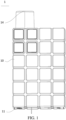
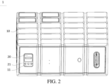
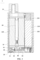
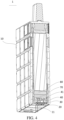
- 1 electronic atomization device; 100: atomizer; 10: housing; 11: first air inlet hole; 12: sliding groove; 13: first convex rib; 14: outlet hole; 20: inhalation resistance adjustment member; 21: second air inlet hole; 22: body; 23: operating portion; 24: support portion; 30: first sealing member; 31: third air inlet hole; 311: first opening; 312: second opening; 313: intermediate opening; 32: second convex rib; 33: fixing groove; 34: activation airway; 40: fixing base; 41: fourth air inlet hole; 50: airflow induction member; 60: central tube; 70: liquid absorbing member; 71: fifth air inlet hole; 80: second sealing member; 81: sixth air inlet hole; 82: third convex rib; 821: sealing horizontal rib; 822: sealing vertical rib; 83: cable hole; 200: power supply assembly; 210: battery core; 220: support member.
- orientations or position relationships indicated by terms such as “central”, “vertical”, “horizontal”, “length”, “width”, “thickness”, “above”, “below”, “front”, “rear”, “left”, “right”, “vertical”, “horizontal”, “top”, “bottom”, “inside”, “outside”, “clockwise” and “counterclockwise” are orientations or position relationships indicated based on the accompanying drawings, and are merely used for describing this application and simplifying the descriptions, rather than indicating or implying that the mentioned apparatus or element needs to have a particular orientation or needs to be constructed and operated in a particular orientation. Therefore, such terms should not be construed as limiting of this application.
- first and second are merely used merely for the purpose of descriptions, and should not be construed as indicating or implying relative importance or implying a number of indicated technical features. Therefore, features defined with “first” or “second” may explicitly or implicitly include at least one of such features. In the descriptions of this application, unless otherwise explicitly defined, "a plurality of" means at least two, such as two and three.
- the terms “mount”, “connect”, “couple”, and “fix” should be understood in a generalized manner, for example, may be understood as a fixed connection, a detachable connection, or integration; or may be understood as a mechanical connection or an electrical connection; or may be understood as a direct connection, an indirect connection via a medium, an internal communication of two elements, or a mutual relationship between two elements.
- a person of ordinary skill in the art may understand specific meanings of the terms in this application according to specific situations.
- a first feature "on” or “under” a second feature may mean that the first feature and the second feature are in direct contact, or the first feature and the second feature are in indirect contact through an intermediary.
- the first feature is "above”, “over”, or “on” the second feature may be that the first feature is directly above or obliquely above the second feature, or may merely indicate that the horizontal position of the first feature is higher than the horizontal position of the second feature.
- That the first feature is "below”, “under”, or “beneath” the second feature may be that the first feature is directly below or obliquely below the second feature, or may merely indicate that the horizontal position of the first feature is lower than the horizontal position of the second feature.
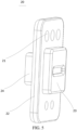
- an electronic atomization device 1 disclosed in at least one embodiment of this application includes a power supply assembly 200 and an atomizer 100.
- the power supply assembly 200 is electrically connected to the atomizer 100.
- the atomizer 100 is configured to atomize an atomizable medium under an action of electric energy provided by the power supply assembly 200 and form an aerosol for a user to inhale.
- the atomizer 100 includes a housing 10.
- the power supply assembly 200 includes a battery core 210 arranged in the housing 10.
- the battery core 210 is configured to provide electrical energy for the atomizer 100 to atomize the atomizable medium. It should be understood that, generally, a main control board configured to control turning on or turning off of the atomizer 100 and a lamp board configured to remind the user are further arranged in the housing 10.
- the battery core 210 is extremely prone to shaking during use. When the battery core 210 shakes, there is a risk that a tab of the battery core 210 is in contact with the main control board and the lamp board, resulting in a short circuit.
- the power supply assembly 200 further includes a support member 220 arranged in the housing 10.
- the support member 220 performs support between at least one pole of the battery core 210 and the housing 10.
- the support member 220 performs support between two poles of the battery core 210 and the housing 10, to support the battery core 210, so as to prevent the battery core 210 from shaking in the housing 10.
- the support member 220 includes foam, and the foam is adhered to the two poles of the battery core 210 through an adhesive paper.
- the housing 10 of the atomizer 100 is provided with a first air inlet hole 11, and external air may enter the housing 10 through the first air inlet hole 11.
- the atomizer 100 further includes an inhalation resistance adjustment member 20 arranged in the housing 10, and the inhalation resistance adjustment member 20 is slidably connected to the housing 10.
- the inhalation resistance adjustment member 20 is provided with a plurality of second air inlet holes 21 with the same air inlet areas. When the inhalation resistance adjustment member 20 is operable to slide relative to the housing 10, at least part of the second air inlet holes 21 are controlled to communicate with the first air inlet hole 11.
- a surface of the housing 10 facing the inhalation resistance adjustment member 20 is provided with a sliding groove 12, the inhalation resistance adjustment member 20 is slidably mated with the sliding groove 12, and the first air inlet hole 11 is provided on a bottom wall of the sliding groove 12 in a run-through manner.
- the size of the sliding groove 12 along a sliding path of the inhalation resistance adjustment member 20 is larger than the size of the inhalation resistance adjustment member 20, so that the inhalation resistance adjustment member 20 is slidable.
- the sliding groove 12 is configured to limit sliding of the inhalation resistance adjustment member 20 between a first position and a second position, and as the inhalation resistance adjustment member 20 slides from the first position to the second position, the area in which the second air inlet holes 21 communicate with the first air inlet hole 11 gradually increases.
- groove walls of the sliding groove 12 located at two opposite ends of the inhalation resistance adjustment member 20 along a sliding direction of the inhalation resistance adjustment member 20 can limit the inhalation resistance adjustment member 20 to the first position and the second position, respectively.
- the inhalation resistance adjustment member 20 when the inhalation resistance adjustment member 20 is located at the first position, the area in which the second air inlet holes 21 communicate with the first air inlet hole 11 is the smallest, so that the inhalation resistance is the largest, when the inhalation resistance adjustment member 20 is located at the second position, the area in which the second air inlet holes 21 communicate with the first air inlet hole 11 is the largest, so that the inhalation resistance is the smallest.
- a first convex rib 13 protrudes from the bottom wall of the sliding groove 12 facing the inhalation resistance adjustment member 20.
- the first convex rib 13 is enclosed on an outer periphery of the first air inlet hole 11, and abuts between the bottom wall of the sliding groove 12 and the inhalation resistance adjustment member 20.
- the first convex rib 13 and the bottom wall of the sliding groove 12 are integrally formed. During actual use, the first convex rib 13 may support the inhalation resistance adjustment member 20.
- the arrangement of the first convex rib 13 can reduce a contact area between the inhalation resistance adjustment member 20 and the bottom wall of the sliding groove 12, so that the user slides smoother, and use comfort of the user is improved.
- the inhalation resistance adjustment member 20 includes a body 22 and an operating portion 23 protruding from the side of the body 22.
- the body 22 is mated with the bottom wall of the sliding groove 12.
- the operating portion 23 is accommodated in the first air inlet hole 11, and is exposed to an air inlet side of the first air inlet hole 11.
- the size of the first air inlet hole 11 is greater than the size of the operating portion 23, and the operating portion 23 is operable to drive the body 22 to slide relative to the bottom wall of the sliding groove 12.
- the user may push the operating portion 23 with a finger, so that the operating portion 23 moves in the first air inlet hole 11, and drives the body 22 to slide relative to the housing 10. In this way, it is convenient to adjust the quantity or the area in which the second air inlet holes 21 communicate with the first air inlet hole 11, to improve use experience of the user.
- all of the second air inlet holes 21 are provided on the body 22, and on the sliding path of the inhalation resistance adjustment member 20, all of the second air inlet holes 21 are distributed on two sides of the operating portion 23 with uneven quantities.
- the operating portion 23 is operable to drive the body 22 to slide relative to the bottom wall of the sliding groove 12, and the second air inlet holes 21 located on one side of the operating portion 23 communicate with the first air inlet hole 11.
- Two of the second air inlet holes 21 are distributed on one side of the operating portion 23, and the remaining three of the second air inlet holes 21 are distributed on the other side of the operating portion 23.
- two second air inlet holes 21 located on one side of the operating portion 23 communicate with the first air inlet hole 11, and three second air inlet holes 21 on the other side of the operating portion 23 are blocked by the bottom wall of the sliding groove 12; or three second air inlet holes 21 located on one side of the operating portion 23 communicate with the first air inlet hole 11, and two second air inlet holes 21 on the other side of the operating portion 23 are blocked by the bottom wall of the sliding groove 12.
- the atomizer 100 further includes a first sealing member 30, and the first sealing member 30 includes a sealing silicone.
- the atomizer 100 further includes an airflow induction member 50 sealed by the first sealing member 30.
- the first sealing member 30 is provided with an activation airway for the airflow induction member 50.
- the first sealing member 30 is provided with a fixing groove 33.
- the airflow induction member 50 is engaged and sealed in the fixing groove 33.
- the activation airway 34 enables the fourth air inlet hole 41 to communicate with the airflow induction member 50.
- the airflow induction member 50 may be a microphone that can sense a negative pressure, so as to determine whether to turn on the battery core 210 to supply power to a heating element.
- the first sealing member 30 can seal the airflow induction member 50, to construct the activation airway 34; and fix the inhalation resistance adjustment member on the housing, so that a quantity of component parts is reduced, assembly difficulty is reduced, and costs are saved.
- the atomizer 100 further includes a fixing base 40.
- the fixing base 40 is mated with the housing 10, and is located on an air outlet side of the first air inlet hole 11.
- the first sealing member 30 is sealed between the housing 10 and the fixing base 40.
- the first sealing member 30 is provided with a third air inlet hole 31, and the fixing base 40 is provided with a fourth air inlet hole 41 communicating with the third air inlet hole 31.
- the body 22 of the inhalation resistance adjustment member 20 is slidably connected to the side of the first sealing member 30 away from the fixing base 40, and the first air inlet hole 11, the part of the second air inlet holes 21 communicating with the first air inlet hole 11, the third air inlet hole 31, and the fourth air inlet hole 41 sequentially communicate with each other, to form an air inlet channel.
- a second convex rib 32 protrudes from the surface of the first sealing member 30 facing the body 22 of the inhalation resistance adjustment member 20.
- the second convex rib 32 is enclosed on the edge of the end surface of the third air inlet hole 31, and abuts against the first sealing member 30 and the body 22.
- the second convex rib 32 and the first sealing member 30 may be integrally injection molded.
- the second convex rib 32 can seal a gap between the third air inlet hole 31 and the second air inlet holes 21 currently communicating with the first air inlet hole 11, so as to prevent a problem of poor inhalation resistance consistency caused by air leakage.
- the second convex rib 32 can support the body 22. Compared with a manner that the first sealing member 30 directly supports the body 22, a contact area between the body 22 and the first sealing member 30 can be reduced, so that sliding of the body 22 is smoother, thereby improving the user experience.
- the first sealing member 30 is sequentially provided with a first opening 311, an intermediate opening 313, and a second opening 312 along the sliding path of the inhalation resistance adjustment member 20.
- the intermediate opening 313 enables the first opening 311 to communicate with the second opening 312, and the first opening 311, the second opening 312, and the intermediate opening 313 are jointly constructed to form the third air inlet hole 31.
- the support portion 24 is slidably accommodated in the intermediate opening 313, and drives the second air inlet holes 21 located on one side of the operating portion 23 to communicate with the corresponding first opening 311 or the second opening 312.
- the housing 10 is provided with an air outlet hole 14.
- the atomizer 100 further includes a central tube 60 arranged in the housing 10.
- the central tube 60 enables the fourth air inlet hole 41 to communicate with the air outlet hole 14.
- the user inhales through the air outlet hole 14, external air can enter from the first air inlet hole 11 under an action of an inhalation force, is sequentially transmitted through the air inlet channel and the central tube 60 to the air outlet hole 14, and enter the mouth of the user.
- the atomizer 100 further includes a liquid absorbing member 70.
- the liquid absorbing member 70 is provided with a fifth air inlet hole 71.
- the fifth air inlet hole 71 enables the central tube 60 to communicate with the fourth air inlet hole 41.
- the liquid absorbing member 70 is mounted directly above the fourth air inlet hole 41 of the fixing base 40. When airflow exits from the fourth air inlet hole 41, the airflow enters the liquid absorbing member 70, and the liquid absorbing member 70 may perform velocity reduction and noise reduction processing on the airflow.
- the liquid absorbing member 70 includes liquid absorbing cotton.
- the liquid absorbing cotton is in a porous structure, and has a strong liquid absorbing capacity and a strong liquid storage capacity.
- a flow guide groove is further formed on the surface of the fixing base 40, and condensate can be flow guided by the flow guide groove to the liquid absorbing member 70, and is absorbed, to prevent leakage.
- the atomizer 100 further includes a second sealing member 80 mated with the fixing base 40, and the second sealing member 80 is provided with a sixth air inlet hole 81.
- An air inlet end of the central tube 60 fixedly communicates with an air outlet end of the sixth air inlet hole 81, and the fourth air inlet hole 41 communicates with an air inlet end of the sixth air inlet hole 81.
- the second sealing member 80 includes a sealing silicone, to prevent leakage of the atomizable medium and affect the inhalation experience.
- a third convex rib 82 protrudes from the surface of the second sealing member 80 facing the fixing base 40.
- the third convex rib 82 is enclosed on an outer periphery of the sixth air inlet hole 81, and abuts between the fixing base 40 and the second sealing member 80.
- the third convex rib 82 and the second sealing member 80 are integrally injection molded.
- the third convex rib 82 can seal a gap between the fixing base 40 and the second sealing member 80, to prevent external air from entering.
- the second sealing member 80 is further provided with a cable hole 83, and the cable hole 83 is spaced apart from the sixth air inlet hole 81.
- the third convex rib 82 includes a sealing horizontal rib 821 and a sealing vertical rib 822.
- the sealing horizontal rib 821 is configured to prevent external air from entering the sixth air inlet hole 81.
- the sealing vertical rib 822 is configured to isolate the sixth air inlet hole 81 from the cable hole 83, to prevent air in the cable hole 83 from entering the sixth air inlet hole 81. In this way, insensitive activation and unstable inhalation resistance caused by air leakage can be avoided.
Landscapes
- Special Spraying Apparatus (AREA)
Applications Claiming Priority (1)
| Application Number | Priority Date | Filing Date | Title |
|---|---|---|---|
| PCT/CN2022/107502 WO2024016353A1 (zh) | 2022-07-22 | 2022-07-22 | 雾化器及电子雾化装置 |
Publications (2)
| Publication Number | Publication Date |
|---|---|
| EP4559335A1 true EP4559335A1 (de) | 2025-05-28 |
| EP4559335A4 EP4559335A4 (de) | 2025-09-17 |
Family
ID=89616878
Family Applications (1)
| Application Number | Title | Priority Date | Filing Date |
|---|---|---|---|
| EP22951622.4A Pending EP4559335A4 (de) | 2022-07-22 | 2022-07-22 | Zerstäuber und elektronische zerstäubungsvorrichtung |
Country Status (3)
| Country | Link |
|---|---|
| US (1) | US20250160421A1 (de) |
| EP (1) | EP4559335A4 (de) |
| WO (1) | WO2024016353A1 (de) |
Family Cites Families (6)
| Publication number | Priority date | Publication date | Assignee | Title |
|---|---|---|---|---|
| CA3031874C (en) * | 2016-07-27 | 2022-01-04 | Japan Tobacco Inc. | Flavor inhaler |
| CN112568496B (zh) * | 2019-09-27 | 2024-09-27 | 深圳市吉迩科技有限公司 | 气道调节机构、气道调节方法及电子烟 |
| CN112263020B (zh) * | 2020-10-30 | 2024-01-05 | 深圳麦克韦尔科技有限公司 | 一种电子雾化装置以及用于电子雾化装置的电池装置 |
| CN112401321A (zh) * | 2020-12-11 | 2021-02-26 | 深圳市艾维普思科技有限公司 | 一种气溶胶发生器 |
| CN112617286A (zh) * | 2020-12-11 | 2021-04-09 | 深圳市艾维普思科技有限公司 | 气雾生成装置及其供电组件 |
| CN216701649U (zh) * | 2021-12-31 | 2022-06-10 | 深圳市卓尔悦电子科技有限公司 | 进气结构及气溶胶发生装置 |
-
2022
- 2022-07-22 EP EP22951622.4A patent/EP4559335A4/de active Pending
- 2022-07-22 WO PCT/CN2022/107502 patent/WO2024016353A1/zh not_active Ceased
-
2025
- 2025-01-21 US US19/032,950 patent/US20250160421A1/en active Pending
Also Published As
| Publication number | Publication date |
|---|---|
| EP4559335A4 (de) | 2025-09-17 |
| WO2024016353A1 (zh) | 2024-01-25 |
| US20250160421A1 (en) | 2025-05-22 |
Similar Documents
| Publication | Publication Date | Title |
|---|---|---|
| US11703060B1 (en) | Neck-hanging fan | |
| WO2022199281A1 (zh) | 雾化器及电子雾化装置 | |
| CN216147257U (zh) | 雾化组件、雾化器及气溶胶生成装置 | |
| EP3906792B1 (de) | Elektronische zerstäubungsvorrichtung und zerstäuber dafür | |
| US20240334969A1 (en) | Ultrasonic atomizer, and ultrasonic atomization device | |
| CN215013590U (zh) | 电池组件及电子雾化装置 | |
| WO2025208723A1 (zh) | 雾化装置 | |
| EP4559335A1 (de) | Zerstäuber und elektronische zerstäubungsvorrichtung | |
| CN218889270U (zh) | 一种雾化座、雾化器及气溶胶生成装置 | |
| CN116076797A (zh) | 电子雾化器 | |
| CN216568382U (zh) | 连接器、主机及气溶胶发生装置 | |
| CN116584703A (zh) | 一种气溶胶生成装置 | |
| CN215381437U (zh) | 密封组件、雾化器及电子雾化装置 | |
| CN221330232U (zh) | 电子雾化装置和电子雾化系统 | |
| CN219982141U (zh) | 气溶胶生成装置 | |
| WO2024199229A1 (zh) | 雾化器及其电子雾化装置 | |
| CN218483788U (zh) | 雾化器及电子雾化装置 | |
| WO2022199546A1 (zh) | 雾化器及电子雾化装置 | |
| CN220571560U (zh) | 雾化装置及雾化设备 | |
| CN219271881U (zh) | 湿化装置以及通气治疗设备 | |
| CN217937231U (zh) | 一种雾化主机及其气溶胶发生装置 | |
| CN222955786U (zh) | 用于呼吸机的加湿器及呼吸机 | |
| CN223787129U (zh) | 电子雾化装置 | |
| CN223614196U (zh) | 雾化器及电子雾化装置 | |
| CN223247613U (zh) | 雾化设备主机装置、雾化设备和气道装配件 |
Legal Events
| Date | Code | Title | Description |
|---|---|---|---|
| STAA | Information on the status of an ep patent application or granted ep patent |
Free format text: STATUS: THE INTERNATIONAL PUBLICATION HAS BEEN MADE |
|
| PUAI | Public reference made under article 153(3) epc to a published international application that has entered the european phase |
Free format text: ORIGINAL CODE: 0009012 |
|
| STAA | Information on the status of an ep patent application or granted ep patent |
Free format text: STATUS: REQUEST FOR EXAMINATION WAS MADE |
|
| 17P | Request for examination filed |
Effective date: 20250218 |
|
| AK | Designated contracting states |
Kind code of ref document: A1 Designated state(s): AL AT BE BG CH CY CZ DE DK EE ES FI FR GB GR HR HU IE IS IT LI LT LU LV MC MK MT NL NO PL PT RO RS SE SI SK SM TR |
|
| REG | Reference to a national code |
Ref country code: DE Ref legal event code: R079 Free format text: PREVIOUS MAIN CLASS: A24F0040460000 Ipc: A24F0040485000 |
|
| A4 | Supplementary search report drawn up and despatched |
Effective date: 20250819 |
|
| RIC1 | Information provided on ipc code assigned before grant |
Ipc: A24F 40/485 20200101AFI20250812BHEP Ipc: A24F 40/10 20200101ALN20250812BHEP |
|
| DAV | Request for validation of the european patent (deleted) | ||
| DAX | Request for extension of the european patent (deleted) | ||
| GRAP | Despatch of communication of intention to grant a patent |
Free format text: ORIGINAL CODE: EPIDOSNIGR1 |
|
| STAA | Information on the status of an ep patent application or granted ep patent |
Free format text: STATUS: GRANT OF PATENT IS INTENDED |
|
| RIC1 | Information provided on ipc code assigned before grant |
Ipc: A24F 40/485 20200101AFI20260317BHEP Ipc: A24F 40/10 20200101ALN20260317BHEP |
|
| RIC1 | Information provided on ipc code assigned before grant |
Ipc: A24F 40/485 20200101AFI20260324BHEP Ipc: A24F 40/10 20200101ALN20260324BHEP |