EP4559580A1 - Puce de trajet d'écoulement - Google Patents
Puce de trajet d'écoulement Download PDFInfo
- Publication number
- EP4559580A1 EP4559580A1 EP23842851.0A EP23842851A EP4559580A1 EP 4559580 A1 EP4559580 A1 EP 4559580A1 EP 23842851 A EP23842851 A EP 23842851A EP 4559580 A1 EP4559580 A1 EP 4559580A1
- Authority
- EP
- European Patent Office
- Prior art keywords
- channel
- filter layers
- common
- filter
- liquid
- Prior art date
- Legal status (The legal status is an assumption and is not a legal conclusion. Google has not performed a legal analysis and makes no representation as to the accuracy of the status listed.)
- Pending
Links
Images



Classifications
-
- B—PERFORMING OPERATIONS; TRANSPORTING
- B03—SEPARATION OF SOLID MATERIALS USING LIQUIDS OR USING PNEUMATIC TABLES OR JIGS; MAGNETIC OR ELECTROSTATIC SEPARATION OF SOLID MATERIALS FROM SOLID MATERIALS OR FLUIDS; SEPARATION BY HIGH-VOLTAGE ELECTRIC FIELDS
- B03C—MAGNETIC OR ELECTROSTATIC SEPARATION OF SOLID MATERIALS FROM SOLID MATERIALS OR FLUIDS; SEPARATION BY HIGH-VOLTAGE ELECTRIC FIELDS
- B03C5/00—Separating dispersed particles from liquids by electrostatic effect
- B03C5/005—Dielectrophoresis, i.e. dielectric particles migrating towards the region of highest field strength
-
- G—PHYSICS
- G01—MEASURING; TESTING
- G01N—INVESTIGATING OR ANALYSING MATERIALS BY DETERMINING THEIR CHEMICAL OR PHYSICAL PROPERTIES
- G01N33/00—Investigating or analysing materials by specific methods not covered by groups G01N1/00 - G01N31/00
- G01N33/48—Biological material, e.g. blood, urine; Haemocytometers
- G01N33/483—Physical analysis of biological material
- G01N33/487—Physical analysis of biological material of liquid biological material
- G01N33/49—Blood
- G01N33/491—Blood by separating the blood components
-
- B—PERFORMING OPERATIONS; TRANSPORTING
- B01—PHYSICAL OR CHEMICAL PROCESSES OR APPARATUS IN GENERAL
- B01D—SEPARATION
- B01D29/00—Filters with filtering elements stationary during filtration, e.g. pressure or suction filters, not covered by groups B01D24/00 - B01D27/00; Filtering elements therefor
- B01D29/44—Edge filtering elements, i.e. using contiguous impervious surfaces
-
- B—PERFORMING OPERATIONS; TRANSPORTING
- B01—PHYSICAL OR CHEMICAL PROCESSES OR APPARATUS IN GENERAL
- B01D—SEPARATION
- B01D35/00—Filtering devices having features not specifically covered by groups B01D24/00 - B01D33/00, or for applications not specifically covered by groups B01D24/00 - B01D33/00; Auxiliary devices for filtration; Filter housing constructions
- B01D35/06—Filters making use of electricity or magnetism
-
- B—PERFORMING OPERATIONS; TRANSPORTING
- B01—PHYSICAL OR CHEMICAL PROCESSES OR APPARATUS IN GENERAL
- B01L—CHEMICAL OR PHYSICAL LABORATORY APPARATUS FOR GENERAL USE
- B01L3/00—Containers or dishes for laboratory use, e.g. laboratory glassware; Droppers
- B01L3/50—Containers for the purpose of retaining a material to be analysed, e.g. test tubes
- B01L3/502—Containers for the purpose of retaining a material to be analysed, e.g. test tubes with fluid transport, e.g. in multi-compartment structures
- B01L3/5027—Containers for the purpose of retaining a material to be analysed, e.g. test tubes with fluid transport, e.g. in multi-compartment structures by integrated microfluidic structures, i.e. dimensions of channels and chambers are such that surface tension forces are important, e.g. lab-on-a-chip
- B01L3/502753—Containers for the purpose of retaining a material to be analysed, e.g. test tubes with fluid transport, e.g. in multi-compartment structures by integrated microfluidic structures, i.e. dimensions of channels and chambers are such that surface tension forces are important, e.g. lab-on-a-chip characterised by bulk separation arrangements on lab-on-a-chip devices, e.g. for filtration or centrifugation
-
- B—PERFORMING OPERATIONS; TRANSPORTING
- B03—SEPARATION OF SOLID MATERIALS USING LIQUIDS OR USING PNEUMATIC TABLES OR JIGS; MAGNETIC OR ELECTROSTATIC SEPARATION OF SOLID MATERIALS FROM SOLID MATERIALS OR FLUIDS; SEPARATION BY HIGH-VOLTAGE ELECTRIC FIELDS
- B03C—MAGNETIC OR ELECTROSTATIC SEPARATION OF SOLID MATERIALS FROM SOLID MATERIALS OR FLUIDS; SEPARATION BY HIGH-VOLTAGE ELECTRIC FIELDS
- B03C5/00—Separating dispersed particles from liquids by electrostatic effect
- B03C5/02—Separators
- B03C5/022—Non-uniform field separators
- B03C5/026—Non-uniform field separators using open-gradient differential dielectric separation, i.e. using electrodes of special shapes for non-uniform field creation, e.g. Fluid Integrated Circuit [FIC]
-
- C—CHEMISTRY; METALLURGY
- C12—BIOCHEMISTRY; BEER; SPIRITS; WINE; VINEGAR; MICROBIOLOGY; ENZYMOLOGY; MUTATION OR GENETIC ENGINEERING
- C12M—APPARATUS FOR ENZYMOLOGY OR MICROBIOLOGY; APPARATUS FOR CULTURING MICROORGANISMS FOR PRODUCING BIOMASS, FOR GROWING CELLS OR FOR OBTAINING FERMENTATION OR METABOLIC PRODUCTS, i.e. BIOREACTORS OR FERMENTERS
- C12M33/00—Means for introduction, transport, positioning, extraction, harvesting, peeling or sampling of biological material in or from the apparatus
- C12M33/14—Means for introduction, transport, positioning, extraction, harvesting, peeling or sampling of biological material in or from the apparatus with filters, sieves or membranes
-
- B—PERFORMING OPERATIONS; TRANSPORTING
- B01—PHYSICAL OR CHEMICAL PROCESSES OR APPARATUS IN GENERAL
- B01L—CHEMICAL OR PHYSICAL LABORATORY APPARATUS FOR GENERAL USE
- B01L2300/00—Additional constructional details
- B01L2300/06—Auxiliary integrated devices, integrated components
- B01L2300/0681—Filter
-
- B—PERFORMING OPERATIONS; TRANSPORTING
- B01—PHYSICAL OR CHEMICAL PROCESSES OR APPARATUS IN GENERAL
- B01L—CHEMICAL OR PHYSICAL LABORATORY APPARATUS FOR GENERAL USE
- B01L2300/00—Additional constructional details
- B01L2300/08—Geometry, shape and general structure
- B01L2300/0861—Configuration of multiple channels and/or chambers in a single devices
- B01L2300/0864—Configuration of multiple channels and/or chambers in a single devices comprising only one inlet and multiple receiving wells, e.g. for separation, splitting
-
- B—PERFORMING OPERATIONS; TRANSPORTING
- B01—PHYSICAL OR CHEMICAL PROCESSES OR APPARATUS IN GENERAL
- B01L—CHEMICAL OR PHYSICAL LABORATORY APPARATUS FOR GENERAL USE
- B01L2400/00—Moving or stopping fluids
- B01L2400/04—Moving fluids with specific forces or mechanical means
- B01L2400/0403—Moving fluids with specific forces or mechanical means specific forces
- B01L2400/0415—Moving fluids with specific forces or mechanical means specific forces electrical forces, e.g. electrokinetic
- B01L2400/0424—Dielectrophoretic forces
-
- B—PERFORMING OPERATIONS; TRANSPORTING
- B03—SEPARATION OF SOLID MATERIALS USING LIQUIDS OR USING PNEUMATIC TABLES OR JIGS; MAGNETIC OR ELECTROSTATIC SEPARATION OF SOLID MATERIALS FROM SOLID MATERIALS OR FLUIDS; SEPARATION BY HIGH-VOLTAGE ELECTRIC FIELDS
- B03C—MAGNETIC OR ELECTROSTATIC SEPARATION OF SOLID MATERIALS FROM SOLID MATERIALS OR FLUIDS; SEPARATION BY HIGH-VOLTAGE ELECTRIC FIELDS
- B03C2201/00—Details of magnetic or electrostatic separation
- B03C2201/26—Details of magnetic or electrostatic separation for use in medical or biological applications
-
- G—PHYSICS
- G01—MEASURING; TESTING
- G01N—INVESTIGATING OR ANALYSING MATERIALS BY DETERMINING THEIR CHEMICAL OR PHYSICAL PROPERTIES
- G01N33/00—Investigating or analysing materials by specific methods not covered by groups G01N1/00 - G01N31/00
- G01N33/48—Biological material, e.g. blood, urine; Haemocytometers
- G01N33/483—Physical analysis of biological material
- G01N33/487—Physical analysis of biological material of liquid biological material
- G01N33/48707—Physical analysis of biological material of liquid biological material by electrical means
-
- G—PHYSICS
- G01—MEASURING; TESTING
- G01N—INVESTIGATING OR ANALYSING MATERIALS BY DETERMINING THEIR CHEMICAL OR PHYSICAL PROPERTIES
- G01N33/00—Investigating or analysing materials by specific methods not covered by groups G01N1/00 - G01N31/00
- G01N33/48—Biological material, e.g. blood, urine; Haemocytometers
- G01N33/483—Physical analysis of biological material
- G01N33/487—Physical analysis of biological material of liquid biological material
- G01N33/48707—Physical analysis of biological material of liquid biological material by electrical means
- G01N33/48728—Investigating individual cells, e.g. by patch clamp, voltage clamp
Definitions
- the present invention relates to a channel chip.
- Patent Literature 1 discloses a channel chip including a replacement portion that extracts cells having a predetermined size or larger from blood, and a separation portion that separates cancer cells from a plurality of types of cells that has passed through the replacement portion by means of a dielectrophoretic force.
- Patent Literature 1 Japanese Patent Application Publication No. 2017-134020
- the present invention has been made in view of the above problems, and an object of the present invention is to provide a channel chip capable of processing more sample liquid.
- a channel chip includes a plurality of filter layers, a common supply passage, a common channel, and a dielectrophoretic layer.
- Each of the plurality of filter layers has a hydrodynamic filter.
- the common supply passage supplies a sample liquid to the hydrodynamic filters of the plurality of filter layers.
- a liquid that has passed through the plurality of hydrodynamic filters passes through the common channel.
- the dielectrophoretic layer has electrodes that cause dielectrophoresis of dielectric particles contained in the liquid passing through the common channel.
- the plurality of filter layers and the dielectrophoretic layer are stacked.
- the plurality of filter layers may include a first filter layer stacked on the dielectrophoretic layer and one or more second filter layers stacked on the first filter layer.
- the common channel may be disposed in the first filter layer.
- the plurality of filter layers may include a plurality of the second filter layers.
- the channel chip may include a plurality of outlet-side connection channels connecting outlets of the hydrodynamic filters of the plurality of second filter layers and the common channel.
- the plurality of outlet-side connection channels may extend to the first filter layer and be connected to the common channel without joining together in the second filter layers.
- each of the filter layers may have the plurality of hydrodynamic filters.
- the plurality of hydrodynamic filters of each of the filter layers may be disposed symmetrically with respect to the common channel.
- the channel chip may include a plurality of inlet-side connection channels that connect the common supply passage and inlets of the plurality of hydrodynamic filters in each of the filter layers.
- the plurality of inlet-side connection channels may have substantially the same channel length.
- the channel chip may include a first recovery passage and a pair of second recovery passages connected to a downstream portion of the common channel.
- the pair of second recovery passages may be disposed such as to sandwich the first recovery passage.
- the dielectric particles separated from the liquid passing through the hydrodynamic filter may flow through the first recovery passage.
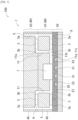
- FIG. 1 is a cross-sectional view schematically illustrating a structure of the separation device 100 including the channel chip 1 according to a preferred embodiment of the present invention.
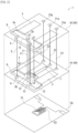
- FIG. 2 is a perspective view schematically illustrating a structure in which the channel chip 1 is disassembled into a plurality of filter layers 40 and a dielectrophoretic layer 50.
- the separation device 100 of the present preferred embodiment includes the channel chip 1.
- the channel chip 1 includes the plurality of filter layers 40 and the dielectrophoretic layer 50.
- Each of the plurality of filter layers 40 has hydrodynamic filters 3 (Hydrodynamic filtration: HDF) (hereinafter referred to as the HDFs 3).
- the HDF 3 is indicated by rectangular broken lines in FIG. 1 .
- the channel chip 1 is a microchannel chip for the purpose of separating and concentrating fine particles.
- the channel chip 1 can separate specific cells from blood as described later.
- the plurality of filter layers 40 and the dielectrophoretic layer 50 are stacked. Therefore, since the plurality of HDFs 3 are disposed for one channel chip 1, it is possible to process more sample liquid L1 described later. Also, it is not necessary to provide the dielectrophoretic layer 50 for each of the plurality of HDFs 3. That is, it is not necessary to provide the same number of dielectrophoretic layers 50 as the number of HDFs 3. Therefore, it is possible to suppress an increase in the size of the channel chip 1 or an increase in the size of the separation device 100.
- the HDF 3 separates particles larger than a predetermined particle size from the passing sample liquid L1 (see FIG. 5 ). It is noted that the detailed structure of the HDF 3 will be described later.
- the dielectrophoretic layer 50 includes an electrode 51 and an electrode 53.
- the electrode 51 and the electrode 53 are electrodes for dielectrophoresis (DEP) of dielectric particles contained in a liquid passing through a common channel 7 described later. It is noted that the detailed structure of the dielectrophoretic layer 50 will be described later.
- the plurality of filter layers 40 include a first filter layer 41 stacked on the dielectrophoretic layer 50 and one or more second filter layers 42 stacked on the first filter layer 41.
- the common channel 7 to be described later is disposed in the first filter layer 41. Therefore, since the dielectrophoretic layer 50 can be disposed near the common channel 7, the dielectrophoretic force can be easily applied to the dielectric particles contained in the liquid passing through the common channel 7.
- the second filter layer 42 can be easily stacked as compared with a case where the first filter layer 41 is disposed on one surface of the dielectrophoretic layer 50 and the second filter layer 42 is disposed on the other surface of the dielectrophoretic layer 50.
- the channel chip 1 can be easily manufactured as compared with a case where the plurality of filter layers 40 are disposed such as to sandwich the dielectrophoretic layer 50.
- the channel chip 1 further includes a first common supply passage 5 and the common channel 7.
- the first common supply passage 5 is an example of the "common supply passage" of the present invention.
- the first common supply passage 5 extends in a stacking direction of the filter layer 40 and the dielectrophoretic layer 50.
- the first common supply passage 5 supplies the sample liquid L1 to the HDF 3 of the plurality of filter layers 40.
- two first common supply passages 5 are illustrated in FIG. 1 in order to facilitate understanding, only one first common supply passage 5 may be provided as illustrated in FIG. 2 .
- an outlet 3b of the HDF 3 of the plurality of filter layers 40 is connected to the common channel 7.
- the liquid that has passed through the plurality of HDFs 3 flows through the common channel 7.
- each of the filter layers 40 has a plurality of the HDFs 3 (here, two HDFs 3). Therefore, as compared with a case where each of the filter layers 40 has only one HDF 3, one channel chip 1 can process more sample liquid L1.
- the plurality of HDFs 3 of each filter layer 40 are disposed symmetrically with respect to the common channel 7. Therefore, the design of each filter layer 40 can be simplified. Also, among the plurality of HDFs 3 of each filter layer 40, the dimensions (the lengths, widths, and depths) of channels (main channels 31 and auxiliary channels 33 to be described later) constituting the HDFs 3 are formed to be the same as each other. In the present preferred embodiment, in all filter layers 40, the channels constituting the HDF 3 are formed to have the same dimensions.
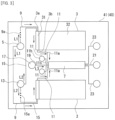
- FIG. 3 is a plan view schematically illustrating a structure of the first filter layer 41.
- FIG. 4 is a plan view schematically illustrating a structure of the second filter layer 42.
- the channel chip 1 further includes a first connection channel 9 and a second connection channel 11. It is noted that the first connection channel 9 is an example of the "inlet-side connection channel" of the present invention. Also, the second connection channel 11 is an example of the "outlet-side connection channel" of the present invention.
- the first connection channel 9 connects the first common supply passage 5 and an inlet 3a of the HDF 3.
- the channel chip 1 includes a plurality of first connection channels 9 in each filter layer 40.
- channel lengths from the first common supply passage 5 to the inlets 3a of the plurality of HDFs 3 are substantially the same. That is, in each filter layer 40, the channel lengths of a plurality of the first connection channels 9 (here, two first connection channels 9) are substantially the same. Therefore, when the sample liquid L1 is supplied to the first common supply passage 5, the sample liquid L1 flows through the plurality of HDFs 3 substantially simultaneously in each filter layer 40. Therefore, since the sample liquid L1 flows under substantially the same condition with respect to the plurality of HDFs 3, it is possible to suppress variation in the separation performance by the HDFs 3.
- At least one first connection channel 9 has a bypass portion 9a in order to make the channel lengths of the plurality of first connection channels 9 substantially the same, the bypass portion 9a is drawn with three dots in order to simplify the drawing.
- the cross-sectional dimensions such as the widths and depths of the plurality of first connection channels 9 are substantially the same. It is noted that, among the plurality of filter layers 40, the channel lengths and the cross-sectional dimensions of the first connection channels 9 may be substantially the same, or may be different in consideration of channel resistance or the like.
- the second connection channel 11 connects the outlet 3b of the HDF 3 and the common channel 7.
- the second connection channel 11 connecting the outlet 3b of the HDF 3 of the first filter layer 41 and the common channel 7 is constituted by a first portion 11a extending in a planar direction (the direction orthogonal to the stacking direction) from the outlet 3b of the HDF 3.
- the second connection channel 11 connecting the outlet 3b of the HDF 3 of the second filter layer 42 and the common channel 7 includes the first portion 11a extending in the plane direction from the outlet 3b of the HDF 3, a second portion 11b extending in the stacking direction from the first portion 11a, and a third portion 11c extending in the plane direction from the second portion 11b and connected to the common channel 7.
- the first portion 11a and the third portion 11c are illustrated as a common portion on the first filter layer 41 in FIG. 1 in order to simplify the drawing.
- the channel chip 1 further includes a second common supply passage 13 and a third connection channel 15. It is noted that the second common supply passage 13 and the third connection channel 15 are omitted in FIG. 1 in order to simplify the drawing. As illustrated in FIGS. 2 to 4 , the second common supply passage 13 extends in the stacking direction of the filter layer 40 and the dielectrophoretic layer 50. The second common supply passage 13 supplies a transport liquid L2 (see FIG. 5 ) to the HDF 3 of the plurality of filter layers 40. The third connection channel 15 connects the second common supply passage 13 and the inlet 3a of the HDF 3.
- each filter layer 40 the channel lengths from the second common supply passage 13 to the inlets 3a of the plurality of HDFs 3 are substantially the same. That is, in each filter layer 40, the channel lengths of a plurality of the third connection channels 15 (here, two third connection channels 15) are substantially the same. It is noted that, although at least one third connection channel 15 has a bypass portion 15a in order to make the channel lengths of the plurality of third connection channels 15 substantially the same, the bypass portion 15a is drawn with three dots in order to simplify the drawing. Also, in each filter layer 40, the cross-sectional dimensions such as the widths and depths of the plurality of third connection channels 15 are substantially the same. It is noted that, among the plurality of filter layers 40, the channel lengths and the cross-sectional dimensions of the third connection channels 15 may be substantially the same, or may be different in consideration of channel resistance or the like.
- the channel chip 1 further includes a recovered liquid supply passage 17 and a fourth connection channel 19. It is noted that the recovered liquid supply passage 17 and the fourth connection channel 19 are omitted in FIG. 1 in order to simplify the drawing.
- the recovered liquid supply passage 17 supplies a recovered liquid L3 (see FIG. 10 ) to the common channel 7.
- the recovered liquid L3 is not particularly limited but is, for example, the same in components as the transport liquid L2. It is noted that the recovered liquid L3 may be different in components than the transport liquid L2.
- the fourth connection channel 19 is disposed in the first filter layer 41. The fourth connection channel 19 connects the recovered liquid supply passage 17 and the common channel 7.
- the dielectrophoretic layer 50 further includes a substrate 55 and an insulating protective film 57 in addition to the electrode 51 and the electrode 53.
- the substrate 55 is not particularly limited but is made of, for example, glass. In the present preferred embodiment, the substrate 55 is made of quartz glass. Also, the substrate 55 is a substantially rectangular flat plate, for example.
- the electrode 51 and the electrode 53 are disposed on one surface of the substrate 55.
- the electrode 51 and the electrode 53 are made of metal such as aluminum or copper, for example.
- the electrode 51 and the electrode 53 are formed in a predetermined shape by, for example, a vacuum deposition method, a photolithography method, and an etching method.
- the insulating protective film 57 covers the electrode 51, the electrode 53, and the substrate 55.
- the insulating protective film 57 is not particularly limited but is, for example, an oxide film such as a silicon oxide film or a silicon nitride film.
- the insulating protective film 57 suppresses, for example, time degradation of the electrode 51 and the electrode 53 due to moisture.
- the filter layer 40 further includes insulation layers 45.
- the insulation layer 45 is made of, for example, resin. In the present preferred embodiment, the insulation layer 45 is transparent.
- the insulation layer 45 is formed from, for example, dimethylpolysiloxane (PDMS).
- PDMS dimethylpolysiloxane
- the HDF 3 and various channels are formed.
- the plurality of filter layers 40 are formed, for example, by sequentially stacking, on the dielectrophoretic layer 50, the plurality of insulation layers 45 in which the HDFs 3 and various channels are formed. It is noted that the filter layer 40 may be formed, for example, by stacking an uncured resin on the dielectrophoretic layer 50 and curing the resin.
- FIG. 5 is a plan view schematically illustrating a structure of the HDF 3.
- the HDF 3 includes the main channel 31 and a plurality of the auxiliary channels 33.
- the main channel 31 extends in a straight-line form toward, for example, a predetermined direction.
- a sample liquid L1 flows through the main channel 31.
- the sample liquid L1 and the transport liquid L2 flow through the main channel 31.
- the sample liquid L1 is a liquid containing fine particles.
- the sample liquid L1 is not particularly limited but is blood, for example.
- the transport liquid L2 is a liquid not containing fine particles, for example.
- the transport liquid L2 is not particularly limited but is a liquid culture media, for example.
- the plurality of auxiliary channels 33 branch from the main channel 31. Specifically, the plurality of auxiliary channels 33 are disposed at substantially equal pitches along the direction in which the main channel 31 extends, for example.
- the plurality of auxiliary channels 33 have the same length, for example.
- the plurality of auxiliary channels 33 extend in a direction intersecting the main channel 31. In the present preferred embodiment, the plurality of auxiliary channels 33 extend in a direction orthogonal to the main channel 31.
- the plurality of auxiliary channels 33 are formed so that channel resistance is gradually reduced from the upstream side of the main channel 31 toward the downstream side.
- a portion on the proximal end side (a side close to the main channel 31) of each of the auxiliary channels 33 is formed to have a first width.
- a portion of each auxiliary channel 33 which is located on the terminal side (the side far from the main channel 31) is formed to have a second width larger than the first width. Then, the position where the width of the auxiliary channel 33 changes from the first width to the second width is disposed closer to the proximal end side as the auxiliary channel is closer to the downstream side.
- the first width is not particularly limited but is, for example, about 10 ⁇ m to several 10 ⁇ m.
- the second width is not particularly limited but is about several 10 ⁇ m to 100 ⁇ m, for example. It is noted that all of the auxiliary channels 33 may be formed to have the same constant width. In this case, for example, the auxiliary channel 33 closer to the downstream side may be formed shorter.
- part of the liquid flowing through the main channel 31 flows into the plurality of auxiliary channels 33. Also, part of the particles contained in the liquid flowing through the main channel 31 flows into the plurality of auxiliary channels 33. Whether or not the particles flow into the plurality of auxiliary channels 33 depends on, for example, the particle size.
- blood plasma also called as plasma
- red blood cells and blood platelets flow to the auxiliary channel 33 and inhibit cancer cells and white blood cells contained in blood from flowing to the auxiliary channel 33. That is, it is possible to separate the particles having the large particle sizes, such as cancer cells and the white blood cells, from blood.
- FIGS. 3 and 4 when the sample liquid L1 is supplied to the first common supply passage 5 and the transport liquid L2 is supplied to the second common supply passage 13, the sample liquid L1 and the transport liquid L2 flow through the main channel 31 via the first connection channel 9 and the third connection channel 15, respectively.
- the sample liquid L1 flows along an inner wall 31a on the auxiliary channels 33 side
- the transport liquid L2 flows along an inner wall 31b on the opposite side to the auxiliary channels 33.
- centers of various particles pass through positions separated from the inner wall 31a of the main channel 31 by not less than radii of the particles.
- the flow speed changes according to the position of the main channel 31 in the width direction. Specifically, the flow speed decreases near the inner wall 31a and the inner wall 31b of the main channel 31. On the other hand, the flow speed is the largest at a position far from the inner wall 31a and the inner wall 31b of the main channel 31 (the center of the main channel 31 in the width direction).
- the particles of the predetermined size or smaller do not reach the downstream end (the outlet 3b of the HDF 3) of the main channel 31. It is noted that blood plasma serving as a liquid component does not reach the downstream end of the main channel 31 as well. Therefore, it is possible to separate, for example, the particles having the large particle sizes, such as cancer cells and the white blood cells, from blood by the channel chip 1.
- FIG. 6 is a view schematically illustrating a structure around the common channel 7.
- the common channel 7 is disposed in the first filter layer 41.
- the common channel 7 extends in a straight-line form toward a predetermined direction.
- the common channel 7 has a joining portion 7a and a branch portion 7b.
- the joining portion 7a is disposed at the upstream-side end portion of the common channel 7.
- the branch portion 7b is disposed at the downstream-side end portion of the common channel 7.
- the second connection channel 11 is connected to the upstream end of the common channel 7.
- four second connection channels 11 are connected to the upstream end of the common channel 7.
- the fourth connection channel 19 is connected to the upstream end of the common channel 7.
- the fourth connection channel 19 is disposed between the two second connection channels 11 and the two second connection channels 11. It is noted that the four second connection channels 11 are disposed symmetrically with respect to the fourth connection channel 19. The second connection channel 11 and the fourth connection channel 19 join together at the joining portion 7a of the common channel 7.
- the channel chip 1 further includes a first recovery passage 21 and a second recovery passage 23 which are connected to a downstream portion of the common channel 7.
- the channel chip 1 includes the first recovery passage 21 connected to a downstream portion of the common channel 7 and a pair of the second recovery passages 23.
- the first recovery passage 21 and the pair of second recovery passage 23 are connected to the downstream end of the common channel 7.
- the common channel 7 branches into the first recovery passage 21 and the pair of second recovery passages 23 at the branch portion 7b.
- the pair of second recovery passages 23 are disposed such as to sandwich the first recovery passage 21. Therefore, as described later, when a target to be recovered (here, cancer cells) is recovered from the first recovery passage 21, the target to be recovered can be recovered from one first recovery passage 21. Therefore, the target to be recovered can be easily recovered as compared with the case where a pair of the first recovery passages 21 are provided.
- a target to be recovered here, cancer cells
- the first recovery passage 21 and the second recovery passage 23 are led out in the plane direction from the common channel 7 and then extend in the stacking direction.
- the first recovery passage 21 and the second recovery passage 23 each have an outlet 21a and an outlet 23a.
- the outlet 21a and the outlet 23a are disposed in the second filter layer 42.
- the liquid that has passed through the first recovery passage 21 is recovered to the first recovery portion (not illustrated) via the outlet 21a.
- the first recovery portion includes a recovery container, for example.
- the liquid that has passed through the second recovery passage 23 is recovered to the second recovery portion (not illustrated) via the outlet 23a.
- the second recovery portion includes a recovery container, for example. It is noted that, in the present preferred embodiment, as will be described later, dielectric particles (here, cancer cells) separated from the liquid that has passed through the HDF 3 flow into the first recovery passage 21.
- FIG. 7 is a plan view schematically illustrating a structure of the dielectrophoretic layer 50.
- the dielectrophoretic layer 50 further includes a lead-out wiring 52 and a lead-out wiring 54 in addition to the electrode 51 and the electrode 53.
- One end of the lead-out wiring 52 is connected to the electrode 51.
- the lead-out wiring 52 has a terminal portion 52a.
- the terminal portion 52a is disposed at the other end of the lead-out wiring 52.
- the separation device 100 includes an AC source 110, and the terminal portion 52a of the lead-out wiring 52 is electrically connected to the AC source 110.
- the lead-out wiring 54 has a terminal portion 54a.
- the terminal portion 54a is disposed at the other end of the lead-out wiring 54.
- the terminal portion 54a of the lead-out wiring 54 is electrically connected to the AC source 110. An AC voltage is applied between the terminal portion 52a and the terminal portion 54a by the AC source 110.
- FIG. 8 is a plan view schematically illustrating a structures of the common channel 7, the electrode 51, and the electrode 53.
- FIG. 9 is a plan view schematically illustrating a structure of the channel chip 1. It is noted that, in order to facilitate understanding, the first filter layer 41 and the second filter layer 42 are indicated by solid lines and the dielectrophoretic layer 50 is indicated by broken lines in FIG. 9 .
- the dielectrophoretic layer 50 can further separate particles flowing through the common channel 7 by dielectrophoresis.
- the electrode 51 and the electrode 53 are disposed such as to overlap the common channel 7. That is, the electrode 51 and the electrode 53 face the common channel 7 in the stacking direction.
- the electrode 51 and the electrode 53 are teeth-shaped electrodes opposing each other.
- the teeth portions of the electrode 51 and the electrode 53 are inclined at, for example, 10° or more and 60° or less with respect to the common channel 7.
- the electrode 51 and the teeth portion of the electrode 53 are disposed symmetrically in the width direction of the common channel 7.
- the teeth portions of the electrode 51 and the electrode 53 extend from the outside in the width direction toward the center in the width direction of the common channel 7, from the upstream side toward the downstream side.
- Applying an AC voltage between the electrode 51 and the electrode 53 by the AC source 110 can cause dielectrophoresis of the particles passing through the common channel 7. Adjusting the frequency of the AC voltage to be applied makes it possible to separate and recover desired particles from a plurality of types of particles passing through the common channel 7 by dielectrophoresis.
- the plurality of types of particles passing through the common channel 7 contain dielectric particles
- cancer cells and white blood cells are dielectric particles.
- AC voltage of a particular frequency is applied between the electrode 51 and the electrode 53 so that a dielectrophoretic force is made to easily act on the cancer cells, for example. As illustrated by FIG.
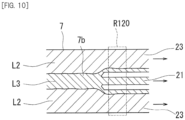
- FIG. 10 is a plan view schematically illustrating a structure around the branch portion 7b of the common channel 7. More specifically, as illustrated in FIG. 10 , the transport liquid L2 does not flow to the first recovery passage 21, and only the recovered liquid L3 flows. In the present preferred embodiment, the transport liquid L2 does not flow to the first recovery passage 21 but flows to the second recovery passage 23. The recovered liquid L3 flows to the first recovery passage 21 and the second recovery passage 23. Therefore, when no dielectrophoretic force is made to act, particles do not flow to the first recovery passage 21. On the other hand, in the present preferred embodiment, for example, cancer cells can be moved from the outside in the width direction to the inside in the width direction of the common channel 7 by making a dielectrophoretic force act. Therefore, it is possible to guide only cancer cells among the plurality of types of particles to the first recovery passage 21.
- the separation device 100 further includes a sample liquid sending portion 61, a transport liquid sending portion 63, and a recovered liquid sending portion 65.
- the separation device 100 may include a control unit that drives the sample liquid sending portion 61, the transport liquid sending portion 63, and the recovered liquid sending portion 65.
- a control unit 131 described later drives the sample liquid sending portion 61, the transport liquid sending portion 63, and the recovered liquid sending portion 65.
- the sample liquid sending portion 61, the transport liquid sending portion 63, and the recovered liquid sending portion 65 are not particularly limited but are, for example, micropumps.
- the micropumps may be mechanical pumps or may be non-mechanical pumps.
- the sample liquid sending portion 61 is connected to the first common supply passage 5 and causes the sample liquid L1 to flow through the first common supply passage 5.
- the sample liquid sending portion 61 supplies the sample liquid L1 to the first common supply passage 5
- the sample liquid L1 flows to the first connection channel 9 and the HDF 3 of each filter layer 40.
- the transport liquid sending portion 63 is connected to the second common supply passage 13 and causes the transport liquid L2 to flow to the second common supply passage 13.
- the transport liquid sending portion 63 supplies the transport liquid L2 to the second common supply passage 13
- the transport liquid L2 flows to the third connection channel 15 and the HDF 3 of each filter layer 40.
- the recovered liquid sending portion 65 is connected to the recovered liquid supply passage 17 and causes the recovered liquid L3 to flow to the recovered liquid supply passage 17.
- the recovered liquid sending portion 65 supplies the recovered liquid L3 to the recovered liquid supply passage 17
- the recovered liquid L3 flows through the fourth connection channel 19 and the common channel 7.
- the sample liquid sending portion 61 supplies the sample liquid L1 so that the sample liquid L1 becomes a laminar flow.
- the transport liquid sending portion 63 supplies the transport liquid L2 so that the transport liquid L2 becomes a laminar flow.
- the recovered liquid sending portion 65 supplies the recovered liquid L3 so that the recovered liquid L3 becomes a laminar flow. Therefore, in the present preferred embodiment, each liquid becomes a laminar flow in the channel chip 1.
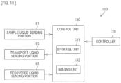
- FIG. 11 is a block diagram illustrating a configuration of the separation device 100.
- the separation device 100 further includes an imaging unit 120 and a controller 130.
- the imaging unit 120 acquires an image of a predetermined region of the channel chip 1.
- the imaging unit 120 transmits captured image data to the control unit 131 (described later) of the controller 130.
- the imaging unit 120 includes, for example, a camera having an imaging element such as a CCD image sensor or a CMOS image sensor, and an optical microscope module.
- the imaging unit 120 may include other cameras or other microscopes.
- the separation device 100 may further include a display unit that displays an image captured by the imaging unit 120.
- the imaging unit 120 is used to check the operation of the channel chip 1. For example, in the present preferred embodiment, the imaging unit 120 is used to check whether or not the HDF 3 has separated particles larger than a predetermined particle size from particles having a predetermined particle size or smaller. Also, in the present preferred embodiment, the imaging unit 120 is used to check whether or not cancer cells and other particles are separated by dielectrophoresis.
- the first recovery passage 21 and the pair of second recovery passages 23 are disposed in an imaging region R120 of the imaging unit 120. Specifically, in the imaging region R120, the entire area of the first recovery passage 21 in the width direction and the entire area of the pair of second recovery passages 23 in the width direction are disposed. Therefore, the imaging unit 120 can image all particles passing through the first recovery passage 21 and all particles passing through the pair of second recovery passages 23. Therefore, the configuration of the separation device 100 can be simplified as compared with a case where one imaging unit 120 is provided for each recovery passage (the first recovery passage 21 and the pair of second recovery passages 23).
- the controller 130 includes the control unit 131 and a storage unit 132.
- the control unit 131 includes a processor.
- the control unit 131 includes, for example, a central processing unit (CPU).
- the storage unit 132 stores data and a computer program.
- the storage unit 132 includes a main storage device and an auxiliary storage device.
- the main storage device is a semiconductor memory, for example.
- the auxiliary storage device is, for example, a semiconductor memory and/or a hard disk drive.
- the storage unit 132 may include a removable media.
- the control unit 131 executes the computer program stored in the storage unit 132 to execute the operation of the separation device 100.
- the control unit 131 receives image data from the imaging unit 120.
- the control unit 131 determines, on the basis of the image data from the imaging unit 120, whether or not particles having a predetermined particle size or smaller have passed through the first recovery passage 21 or the second recovery passage 23.
- the control unit 131 stops driving the sample liquid sending portion 61, the transport liquid sending portion 63, and the recovered liquid sending portion 65.
- control unit 131 determines, on the basis of the image data from the imaging unit 120, whether or not the particles have passed through the second recovery passage 23.
- the control unit 131 stops driving the sample liquid sending portion 61, the transport liquid sending portion 63, and the recovered liquid sending portion 65.
- the control unit 131 may determine, on the basis of the image data from the imaging unit 120, whether or not the particle has passed through the first recovery passage 21. Upon determining that the particles have not passed through the first recovery passage 21, the control unit 131 may stop driving the sample liquid sending portion 61, the transport liquid sending portion 63, and the recovered liquid sending portion 65.
- FIG. 12 is a cross-sectional view schematically illustrating a structure of a separation device 100 including a channel chip 1 according to the first modified example of the present invention.
- the plurality of filter layers 40 includes the two or more second filter layers 42.
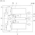
- the plurality of filter layers 40 include the first filter layer 41 and the two or more second filter layers 42 stacked on the first filter layer 41.
- the plurality of filter layers 40 includes the first filter layer 41 and three second filter layers 42. Therefore, the channel chip 1 of the first modified example can process more sample liquid L1 than the channel chip 1 of the preferred embodiment described with reference to FIGS. 1 to 11 . It is noted that the plurality of filter layers 40 may include the two second filter layers 42 or the four or more second filter layers 42.
- the channel chip 1 includes a plurality of the second connection channels 11 that connect the outlets 3b of the HDFs 3 of a plurality of the second filter layers 42 (here, three second filter layers 42) and the common channel 7.
- the plurality of second connection channels 11 extend to the first filter layer 41 and are connected to the common channel 7 without joining each other in the second filter layers 42.
- the second connection channels 11 are joined together in the second filter layers 42, high positioning accuracy is required when the second filter layers 42 are stacked.
- the second connection channels 11 since the second connection channels 11 are not joined together in the second filter layers 42, it is possible to suppress the need for high positioning accuracy when the second filter layers 42 are stacked. That is, it is possible to prevent the manufacturing of the channel chip 1 from becoming complicated.
- the plurality of second connection channels 11 may be joined together in the second filter layers 42 and then connected to the common channel 7 in the first filter layer 41.
- FIG. 13 is a plan view schematically illustrating a structure of the first filter layer 41 of the channel chip 1 according to the second modified example of the present invention.
- the second modified example unlike the preferred embodiment described above with reference to FIGS. 1 to 11 , an example in which the first connection channel 9 and the third connection channel 15 are connected to the HDF 3 after being joined together will be described.
- the first connection channel 9 and the third connection channel 15 are joined together and then connected to the inlet 3a of the HDF 3. Therefore, since the path through which the first connection channel 9 and the third connection channel 15 pass can be simplified, the design of the channel chip 1 can be simplified.
- the second connection channel 11 is connected such as to intersect the common channel 7.
- the second connection channel 11 is connected substantially perpendicularly to the common channel 7.
- the second connection channel 11 is, for example, connected substantially perpendicular to the common channel 7 or connected such as to be inclined with respect to the common channel 7, it is possible to separate specific particles by dielectrophoresis as in the above-described preferred embodiment.
- the plurality of second connection channels 11 may be joined together and then connected to the common channel 7.
- the plurality of filter layers 40 include the first filter layer 41 disposed on one surface of the dielectrophoretic layer 50 and the second filter layer 42 disposed on the first filter layer 41, but the present invention is not limited thereto.
- the plurality of filter layers 40 may include the filter layer 40 disposed on one surface of the dielectrophoretic layer 50 and the filter layer 40 disposed on the other surface of the dielectrophoretic layer 50.
- the common channel 7 is disposed in the first filter layer 41 disposed on one surface of the dielectrophoretic layer 50 among the plurality of filter layers 40 has been described, but the present invention is not limited thereto.
- the common channel 7 may be disposed in any one of the one or more second filter layers 42 stacked on the first filter layer 41.
- the present invention is not limited thereto.
- a layer which does not have the HDF 3 may be separately provided, and the common channel 7 may be disposed in the layer which does not have the HDF 3.
- each filter layer 40 includes the plurality of HDFs 3 has been described, but the present invention is not limited thereto.
- each filter layer 40 may have only one HDF 3.
- the HDF 3 is disposed symmetrically with respect to the common channel 7 in each filter layer 40
- the present invention is not limited thereto.
- the HDF 3 may be disposed symmetrically in each filter layer 40.
- each filter layer 40 an example has been described in which the channel lengths of the plurality of first connection channels 9 are substantially the same and the channel lengths of the plurality of third connection channels 15 are substantially the same, but the present invention is not limited thereto.
- the channel lengths of the plurality of first connection channels 9 may be different.
- the channel lengths of the plurality of third connection channels 15 may be different.
- the recovered liquid sending portion 65 may be capable of adjusting the amount of the recovered liquid L3 to be supplied to the recovered liquid supply passage 17. That is, the recovered liquid sending portion 65 may be capable of adjusting the amount of the recovered liquid L3 flowing through the common channel 7.
- the amounts of the sample liquid L1 and the transport liquid L2 flowing through the common channel 7 are changed by changing the amount of the recovered liquid L3 flowing through the common channel 7. That is, the ease of flow of the sample liquid L1 and the transport liquid L2 with respect to the common channel 7 changes. Therefore, in the HDF 3 connected to the common channel 7, the ease of flow from the main channel 31 to the auxiliary channel 33 changes.
- control unit 131 stops driving the sample liquid sending portion 61, the transport liquid sending portion 63, and the recovered liquid sending portion 65 upon determining that particles having a predetermined particle size or smaller have passed through the first recovery passage 21 or the second recovery passage 23, that the particles have not passed through the second recovery passage 23, or that the particles have not passed through the first recovery passage 21 is described.
- the present invention is not limited thereto.
- the control unit 131 may adjust the amount of the recovered liquid L3 flowing through the common channel 7 so that particles having the predetermined particle size or smaller do not pass through the first recovery passage 21 or the second recovery passage 23. Also, for example, upon determining that the particles have not passed through the second recovery passage 23, the control unit 131 may adjust the amount of the recovered liquid L3 flowing through the common channel 7 so that the particles pass through the second recovery passage 23. Also, for example, upon determining that the particles have not passed through the first recovery passage 21, the control unit 131 may adjust the amount of the recovered liquid L3 flowing through the common channel 7 so that the particles pass through the first recovery passage 21.
- the present invention is not limited thereto.
- a liquid other than blood may be used as the sample liquid L1 and a liquid other than the liquid culture media may be used as the transport liquid L2.
- the particles to be recovered from the outlet 21a are exemplified as a target to be recovered, but the present invention is not limited to this.
- particles or a liquid component to be recovered from the outlet 23a may be the target to be recovered.
- transport liquid L2 and the recovered liquid L3 do not contain particles
- present invention is not limited thereto.
- the transport liquid L2 and the recovered liquid L3 may contain particles. However, it is preferable to separate the particles contained in the transport liquid L2 and the recovered liquid L3 from the particles contained in the sample liquid L1 by dielectrophoresis.
- the example of using the transport liquid L2 has been described. That is, the example in which the transport liquid L2 is made to flow to the HDF 3 in addition to the sample liquid L1 is described.
- the present invention is not limited thereto.
- only the sample liquid L1 may flow into the HDF 3.
- seawater containing particles may be used as the sample liquid L1 to separate the particles from the seawater.
- the present invention is applicable to the field of channel chips.
Landscapes
- Health & Medical Sciences (AREA)
- Chemical & Material Sciences (AREA)
- Life Sciences & Earth Sciences (AREA)
- Engineering & Computer Science (AREA)
- Chemical Kinetics & Catalysis (AREA)
- Molecular Biology (AREA)
- General Health & Medical Sciences (AREA)
- Biomedical Technology (AREA)
- Hematology (AREA)
- Electrochemistry (AREA)
- Analytical Chemistry (AREA)
- Wood Science & Technology (AREA)
- Biochemistry (AREA)
- Bioinformatics & Cheminformatics (AREA)
- Physics & Mathematics (AREA)
- Organic Chemistry (AREA)
- Zoology (AREA)
- Clinical Laboratory Science (AREA)
- Water Supply & Treatment (AREA)
- Dispersion Chemistry (AREA)
- Microelectronics & Electronic Packaging (AREA)
- Food Science & Technology (AREA)
- Genetics & Genomics (AREA)
- Sustainable Development (AREA)
- Microbiology (AREA)
- Ecology (AREA)
- Biotechnology (AREA)
- Biophysics (AREA)
- Urology & Nephrology (AREA)
- General Engineering & Computer Science (AREA)
- Medicinal Chemistry (AREA)
- General Physics & Mathematics (AREA)
- Immunology (AREA)
- Pathology (AREA)
- Apparatus Associated With Microorganisms And Enzymes (AREA)
- Electrostatic Separation (AREA)
- Automatic Analysis And Handling Materials Therefor (AREA)
- Investigating Or Analyzing Materials By The Use Of Electric Means (AREA)
- Physical Or Chemical Processes And Apparatus (AREA)
Applications Claiming Priority (2)
| Application Number | Priority Date | Filing Date | Title |
|---|---|---|---|
| JP2022116506A JP2024013994A (ja) | 2022-07-21 | 2022-07-21 | 流路チップ |
| PCT/JP2023/025289 WO2024018926A1 (fr) | 2022-07-21 | 2023-07-07 | Puce de trajet d'écoulement |
Publications (1)
| Publication Number | Publication Date |
|---|---|
| EP4559580A1 true EP4559580A1 (fr) | 2025-05-28 |
Family
ID=89617845
Family Applications (1)
| Application Number | Title | Priority Date | Filing Date |
|---|---|---|---|
| EP23842851.0A Pending EP4559580A1 (fr) | 2022-07-21 | 2023-07-07 | Puce de trajet d'écoulement |
Country Status (6)
| Country | Link |
|---|---|
| US (1) | US20250381572A1 (fr) |
| EP (1) | EP4559580A1 (fr) |
| JP (1) | JP2024013994A (fr) |
| CN (1) | CN119365266A (fr) |
| TW (1) | TWI852694B (fr) |
| WO (1) | WO2024018926A1 (fr) |
Family Cites Families (9)
| Publication number | Priority date | Publication date | Assignee | Title |
|---|---|---|---|---|
| US6375899B1 (en) * | 1993-11-01 | 2002-04-23 | Nanogen, Inc. | Electrophoretic buss for transport of charged materials in a multi-chamber system |
| US7699767B2 (en) * | 2002-07-31 | 2010-04-20 | Arryx, Inc. | Multiple laminar flow-based particle and cellular separation with laser steering |
| JP2010252785A (ja) * | 2009-03-31 | 2010-11-11 | Kanagawa Acad Of Sci & Technol | 細胞濃縮分離装置 |
| MX344460B (es) * | 2009-12-23 | 2016-12-14 | Cytovera Inc * | Sistema y método para la filtración de partículas. |
| JP6441838B2 (ja) | 2016-01-29 | 2018-12-19 | 株式会社Afiテクノロジー | 解析装置及び分離装置 |
| CA3076601C (fr) * | 2017-10-19 | 2022-08-16 | Tl Genomics Inc. | Puce pour classification de cellules |
| DE102018211001A1 (de) * | 2018-07-04 | 2020-01-09 | Robert Bosch Gmbh | Vorrichtung zum dielektrophoretischen Einfang von Teilchen |
| JP2020099256A (ja) * | 2018-12-21 | 2020-07-02 | 株式会社Afiテクノロジー | 分離方法 |
| US20220390431A1 (en) * | 2019-10-23 | 2022-12-08 | Tl Genomics Inc. | Device for blood |
-
2022
- 2022-07-21 JP JP2022116506A patent/JP2024013994A/ja active Pending
-
2023
- 2023-07-07 US US18/881,083 patent/US20250381572A1/en active Pending
- 2023-07-07 WO PCT/JP2023/025289 patent/WO2024018926A1/fr not_active Ceased
- 2023-07-07 CN CN202380047004.2A patent/CN119365266A/zh active Pending
- 2023-07-07 EP EP23842851.0A patent/EP4559580A1/fr active Pending
- 2023-07-20 TW TW112127077A patent/TWI852694B/zh active
Also Published As
| Publication number | Publication date |
|---|---|
| JP2024013994A (ja) | 2024-02-01 |
| TWI852694B (zh) | 2024-08-11 |
| CN119365266A (zh) | 2025-01-24 |
| US20250381572A1 (en) | 2025-12-18 |
| TW202413941A (zh) | 2024-04-01 |
| WO2024018926A1 (fr) | 2024-01-25 |
Similar Documents
| Publication | Publication Date | Title |
|---|---|---|
| US6822180B2 (en) | Particle separation mechanism | |
| EP3421968B1 (fr) | Analyse optique de particules à l'aide d'un flux de gaine | |
| US20050145497A1 (en) | Implementation of microfluidic components in a microfluidic system | |
| CN110366451B (zh) | 颗粒分离 | |
| US20090226994A1 (en) | Method and Device for Acoustic Manipulation of Particles, Cells and Viruses | |
| US20180250673A1 (en) | Deterministic lateral displacement arrays | |
| EP4559580A1 (fr) | Puce de trajet d'écoulement | |
| US12599903B2 (en) | Leukocyte trapping apparatus | |
| US20200206748A1 (en) | Particle separation device and particle separation apparatus using same | |
| US20260008055A1 (en) | Separation device | |
| Xie et al. | A robust and easily integrated plasma separation chip using gravitational sedimentation of blood cells filling-in high-aspect-ratio weir structure | |
| CN117696134B (zh) | 微流道生物芯片检测装置与使用方法 | |
| US20250033053A1 (en) | Channel chip | |
| US8771493B2 (en) | Liquid dielectrophoretic device and method for controllably transporting a liquid using the same | |
| CN112916058A (zh) | 用于微纳米粒子分选的声学微流控装置 | |
| WO2025004964A1 (fr) | Puce de trajet d'écoulement | |
| WO2024171741A1 (fr) | Puce de trajet d'écoulement et procédé de production de puce de trajet d'écoulement | |
| JP7374392B1 (ja) | 流路デバイスへの液体導入方法 | |
| CN119680382A (zh) | 分离芯片 | |
| JP7515391B2 (ja) | 微粒子捕捉方法及び微粒子捕捉装置 | |
| JP2025103459A (ja) | 分離チップ | |
| WO2023276935A1 (fr) | Puce à canal d'écoulement, système de séparation et procédé de séparation | |
| JP2025003058A (ja) | 粒子分離チップおよび粒子分離装置 | |
| WO2025164557A1 (fr) | Dispositif de voie d'écoulement | |
| JP2023023548A (ja) | 液体取扱装置および液体取扱システム |
Legal Events
| Date | Code | Title | Description |
|---|---|---|---|
| STAA | Information on the status of an ep patent application or granted ep patent |
Free format text: STATUS: THE INTERNATIONAL PUBLICATION HAS BEEN MADE |
|
| PUAI | Public reference made under article 153(3) epc to a published international application that has entered the european phase |
Free format text: ORIGINAL CODE: 0009012 |
|
| STAA | Information on the status of an ep patent application or granted ep patent |
Free format text: STATUS: REQUEST FOR EXAMINATION WAS MADE |
|
| 17P | Request for examination filed |
Effective date: 20241220 |
|
| AK | Designated contracting states |
Kind code of ref document: A1 Designated state(s): AL AT BE BG CH CY CZ DE DK EE ES FI FR GB GR HR HU IE IS IT LI LT LU LV MC ME MK MT NL NO PL PT RO RS SE SI SK SM TR |
|
| P01 | Opt-out of the competence of the unified patent court (upc) registered |
Free format text: CASE NUMBER: APP_26849/2025 Effective date: 20250605 |
|
| DAV | Request for validation of the european patent (deleted) | ||
| DAX | Request for extension of the european patent (deleted) |