EP4559588A1 - Dispositif de transduction ultrasonore - Google Patents
Dispositif de transduction ultrasonore Download PDFInfo
- Publication number
- EP4559588A1 EP4559588A1 EP23211067.6A EP23211067A EP4559588A1 EP 4559588 A1 EP4559588 A1 EP 4559588A1 EP 23211067 A EP23211067 A EP 23211067A EP 4559588 A1 EP4559588 A1 EP 4559588A1
- Authority
- EP
- European Patent Office
- Prior art keywords
- metal layer
- membrane element
- electric voltage
- ultrasound
- ultrasound transducing
- Prior art date
- Legal status (The legal status is an assumption and is not a legal conclusion. Google has not performed a legal analysis and makes no representation as to the accuracy of the status listed.)
- Pending
Links
Images




Classifications
-
- B—PERFORMING OPERATIONS; TRANSPORTING
- B06—GENERATING OR TRANSMITTING MECHANICAL VIBRATIONS IN GENERAL
- B06B—METHODS OR APPARATUS FOR GENERATING OR TRANSMITTING MECHANICAL VIBRATIONS OF INFRASONIC, SONIC, OR ULTRASONIC FREQUENCY, e.g. FOR PERFORMING MECHANICAL WORK IN GENERAL
- B06B1/00—Methods or apparatus for generating mechanical vibrations of infrasonic, sonic, or ultrasonic frequency
- B06B1/02—Methods or apparatus for generating mechanical vibrations of infrasonic, sonic, or ultrasonic frequency making use of electrical energy
- B06B1/0292—Electrostatic transducers, e.g. electret-type
-
- B—PERFORMING OPERATIONS; TRANSPORTING
- B06—GENERATING OR TRANSMITTING MECHANICAL VIBRATIONS IN GENERAL
- B06B—METHODS OR APPARATUS FOR GENERATING OR TRANSMITTING MECHANICAL VIBRATIONS OF INFRASONIC, SONIC, OR ULTRASONIC FREQUENCY, e.g. FOR PERFORMING MECHANICAL WORK IN GENERAL
- B06B1/00—Methods or apparatus for generating mechanical vibrations of infrasonic, sonic, or ultrasonic frequency
- B06B1/02—Methods or apparatus for generating mechanical vibrations of infrasonic, sonic, or ultrasonic frequency making use of electrical energy
- B06B1/06—Methods or apparatus for generating mechanical vibrations of infrasonic, sonic, or ultrasonic frequency making use of electrical energy operating with piezoelectric effect or with electrostriction
- B06B1/0644—Methods or apparatus for generating mechanical vibrations of infrasonic, sonic, or ultrasonic frequency making use of electrical energy operating with piezoelectric effect or with electrostriction using a single piezoelectric element
- B06B1/0662—Methods or apparatus for generating mechanical vibrations of infrasonic, sonic, or ultrasonic frequency making use of electrical energy operating with piezoelectric effect or with electrostriction using a single piezoelectric element with an electrode on the sensitive surface
- B06B1/0666—Methods or apparatus for generating mechanical vibrations of infrasonic, sonic, or ultrasonic frequency making use of electrical energy operating with piezoelectric effect or with electrostriction using a single piezoelectric element with an electrode on the sensitive surface used as a diaphragm
Definitions
- the instant invention concerns an ultrasound transducing device, an ultrasound transducing system, a method for manufacturing an ultrasound transducing device.
- An ultrasound transducing device of this kind generally comprises a carrier device (or wiring carrier device) which has a body comprising at least one cavity limited by a floor element and comprising an opening, wherein a first metal layer is arranged on the floor element and the opening is covered by a flexible membrane element being configured and provided to oscillate in order to transmit and/or receive ultrasound waves.
- the membrane element may comprise a second metal layer which is capacitively connectable to the first metal layer.
- Such an ultrasound transducing device may be used to map its environment through acoustic signals.
- an acoustic wave can be transmitted into an adjacent medium such as tissue or water.
- An object in a propagation direction of the wave may reflect the wave back to the device so that the reflected wave can, inversely, actuate the membrane element to oscillate.
- the induced oscillation of the membrane element may be measured in order to obtain information about the object, for example, its distance to the device.
- Mapping the environment using an ultrasound transducing device as described herein may, for example, be used in a medical device, such as a medical implant, in particular a pacemaker device.
- a medical device such as a medical implant, in particular a pacemaker device.
- An application in a medical device may require coupling of the ultrasound transducing device with tissue and/or water or more generally with an aqueous environment. The device should, therefore, function reliably in aqueous environments without maintenance for several decades.
- an ultrasound transducing device comprises a carrier device which has a body comprising at least one cavity which is limited by a floor element of the body and comprises an opening, wherein a first metal layer is arranged on the floor element, and the opening is covered by a flexible membrane element.
- the flexible membrane element is configured and provided to oscillate in order to transmit and/or receive ultrasound waves.
- the membrane element also comprises a second metal layer, wherein particularly the first metal layer and second metal may form a capacitive arrangement or a capacitor. Particularly, the first metal layer and the second metal layer may be arranged substantially parallel to one another.
- the membrane element further comprises a third metal layer, a piezoelectric foil which is sandwiched between the second and third metal layer.
- the second metal layer and third metal layer may form a capacitive arrangement or capacitor.
- the cavity may comprise two side faces and a base, the base being limited by the floor element of the body of the carrier element.
- the cavity may be filled by an ambient air, e.g., substantially oxygen and nitrogen, wherein particularly the ambient air may form a dielectric of the capacitive arrangement or capacitor formed by the first metal layer and the second metal layer.
- the at least one cavity may be mechanically formed in the body by, e.g., mechanical deep milling, laser ablation or plasma etching.
- a shape of the at least one cavity may be, for example, cylindrical and the opening accordingly circular.
- the membrane element may be disc-shaped (with an effective diameter that is identical to the diameter of the cavity).
- the carrier device may comprise a plurality of cavities that are arranged in the carrier device to form an array.
- the body of the carrier device may be a dielectric element or may at least comprise a dielectric element.
- the carrier device may be flexible.
- the body of the carrier device may be made of a flexible polymer such as polyimide or other thin and flexible polymers.
- the floor element of the at least one cavity may have a first surface facing the inside of the cavity and a second surface facing away from the cavity.
- the at least one cavity may be defined by a wall forming an enclosure which protrudes from the floor element. In this sense, the floor element limits a depth of the at least one cavity and the wall limits its diameter.
- the opening may be arranged opposite from the floor element along a protrusion direction of the wall.
- the first metal layer may be provided at the second surface of the floor element. The floor element and the first metal layer may be considered to form a base of the at least one cavity.
- the cavity may be understood to act as a sound-soft closure, which means that the ultrasound wave will be reflected on the interface between the membrane element and the cavity and propagate in a direction away from the cavity.
- the flexible membrane element may be fixed to the carrier device so that it can freely oscillate within the opening. Such a fixture of the flexible membrane element may, for example, be achieved by an adhesive foil or another way of deploying adhesive material sufficient to attach the membrane to the carrier device. For example, the membrane element may be glued to the carrier device.
- the membrane element may be arranged at the at least one cavity so that the second metal layer faces into the cavity. In this way, the first metal layer and the second metal layer are spaced apart through the at least one cavity and, optionally, the floor element.
- the first and second metal layer may form a capacitive arrangement or capacitor, being particularly coupled by an electric field, wherein an electric voltage applied to the first metal layer and the second metal layer may cause an electric force that acts to decrease the distance between the first and the second metal layer.
- the membrane element By continuously driving an electric field between the first and the second metal layer, the membrane element may be excited to oscillate around an equilibrium position, thereby emitting ultrasound waves.
- the second and third metal layer may form a capacitive arrangement or capacitor in a similar way as the first and the second metal layer.
- An electric voltage field applied to them may, however, act to deform the piezoelectric foil sandwiched between them so that the membrane element is deflected from its equilibrium position and, e.g., forced to arch into the at least one cavity (longitudinal oscillation).
- the applied electric voltage may also cause an electric force that acts to decrease the distance between the second and third metal layer, but the electric voltage required to achieve a deflection through such an electric force will be much higher than the electric voltage necessary to achieve a deflection of the membrane element through a deformation of the piezoelectric foil.
- An electric energy storable by the first and the second metal layer may mainly depend on a deflection of the membrane element and an electric energy storable by the second and third metal layer may mainly depend on a deformation of the piezoelectric foil.
- Ultrasound waves may be transmitted through either the pair of the first and the second metal layer (first capacitor) or the pair of the second and third metal layer (second capacitor) at the same time as receiving ultrasound waves through the respective other pair.
- a control device is configured and provided to apply and/or determine a first electric voltage between the first and second metal layer and a second electric voltage between the second and third metal layer.
- the membrane element may be deflected from its equilibrium position by the electric force.
- the piezoelectric foil may be deformed so that the membrane element is deflected from its equilibrium position. If an ultrasound wave is received through the membrane element, determining the first and/or the second voltage may be used to determine the properties of the ultrasound wave. Because the two electric voltages may be used interchangeably to transmit/receive ultrasound waves, the ultrasound transducing device may be used in a flexible way. Examples are given below.
- the control device may be further configured and provided to vary the first electric voltage during a time interval in which the second electric voltage is held static.
- the properties of the membrane element may be statically adjusted (instead of dynamically changed which is also possible).
- the second electric voltage may cause a significant deflection of the membrane element from its equilibrium position by, e.g., several micrometers.
- a lower first voltage may be used to drive an oscillation of the membrane element.
- control device may be further configured and provided to (dynamically) vary the first and the second electric voltage at the same time.
- the first and the second electric voltage may both be functions of time.
- the second electric voltage may be used to generate a modulation of the intensity of the ultrasound wave generated by the first electric voltage.
- the resonant frequency of the oscillation of the membrane element depends on the applied second electric voltage.
- the ultrasound transducing device may be operated in different modes by statically selecting or dynamically varying the resonant frequency. These modes may include frequency modulation of transmitted ultrasound waves.
- the control device may be further configured and provided to apply the first and the second electric voltage with their phases shifted with respect to each other.
- the phases may, for example, be shifted by 90° with respect to each other so that a resonance exaggeration of an amplitude of the oscillation of the membrane element may be achieved.
- the control device is further configured and provided - in a preferred mode of operation - to apply the first electric voltage in order to drive an oscillation of the membrane element and to concurrently determine the second electric voltage to measure received ultrasound waves. That is, transmission and receipt of ultrasound waves may be carried out separately at the same time since the ultrasound transducing device provides the functions of both a capacitive ultrasound transducer and a piezoelectric ultrasound transducer.
- control device including one or several features of the embodiments described above allows for high-resolution ultrasound imaging for medical and industrial applications in an aqueous environment.
- the piezoelectric foil comprises a polymer and/or the body comprises a polymer material or is formed from a polymer material, wherein the polymer materials, a thermosetting material, particularly an epoxy resin, or a thermoplastic polymer material, particularly a polyimide or liquid crystal polymer.
- the piezoelectric foil comprises a composite material combining a piezo ceramic with a polymer such as a polyimide.
- a composite material may comprise a 1-3 composite or a PZT composite. It may be formed by polymer foil filled with PZT powder.
- a dielectric element, optionally formed by the polymer may be comprised in the body of the carrier device or the body may be formed by the dielectric element as pointed out above.
- the ultrasound transducing device may be designed as a flexible, biostable and biocompatible device so that long term use in a human body is possible with low maintenance.
- Methods of printed circuit board technology may used in the manufacturing process of the device.
- manufacturing costs may be significantly reduced compared to micromechanical methods.
- Another advantage of using polymers for the membrane element is that the coupling of the ultrasound transducing device with tissue and/or water is improved in comparison to using anorganic materials such as AlN.
- an ultrasound transducing system comprising a plurality of ultrasound transducing devices according to the first aspect.
- the plurality of ultrasound transducing devices may be arranged to form an array.
- the array may be operated synchronously in order to obtain a high-resolution map of the environment of the array through acoustic signals.
- a control device is configured and provided to apply and/or determine a first electric voltage between a first and second metal layer and a second electric voltage between a second and third metal layer of each of the plurality of ultrasound transducing devices.
- the array may be operated in a mode comprising synchronous control of the array. In particular, the array may be operated to allow beam shaping of the transmitted ultrasound wave.
- a method for manufacturing an ultrasound transducing device comprises the following steps: providing a carrier device with a body comprising at least one cavity, which is limited by a floor element of the body and comprises an opening, metallizing a surface of the floor element with a first metal layer, providing a flexible piezoelectric foil, metallizing two surfaces of the piezoelectric foil with a second and third metal layer to form a membrane element, and arranging the membrane element on the carrier device so that the opening is covered, and particularly the first and second metal layer may form a capacitive arrangement or a capacitor rd.
- the membrane element is arranged on the carrier device such that the first metal layer and the second metal layer are arranged substantially parallel to one another particularly in order to form a capacitive arrangement or capacitor.
- providing the carrier device comprises mechanically forming the at least one cavity in the body of the carrier device, e.g., by mechanical deep milling, laser ablation or plasma or chemical etching.
- an ultrasound transducing device comprising a carrier device, which has a body, said body comprising at least one cavity being limited by a floor element of the body and an opening, wherein a first metal layer is arranged on the floor element, and the opening is covered by a flexible membrane element being configured and provided to oscillate in order to transmit and/or receive ultrasound waves, said membrane element comprising a second metal layer, wherein particularly the first metal layer and the second metal layer may form a capacitive arrangement or capacitor.
- the body comprises or is formed from a polymer material, in particular a thermoset polymer material, particularly an epoxy resin, or a thermoplastic material, particularly a polyimide or liquid crystal polymer.
- the ultrasound transducing device may have the advantages and advantageous features described with respect to the first to third aspects. It may, in particular, form a portion of an ultrasound transducing system according the second aspect.
- the membrane element comprises a third metal layer, which may for a capacitive arrangement , and a piezoelectric foil which is sandwiched between the second and the third metal layer.
- the membrane element may only comprise the second metal layer, i.e., be formed as a metal foil.
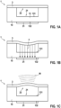
- Fig. 1A to 1C show schematic cross-sections of an ultrasound transducing device operated to transmit ultrasound waves.
- the ultrasound transducing device comprises a carrier device 1 which has a cavity 2.
- the cavity 2 comprises a base 21 and an opening 22, wherein the base 21 is limited by a floor element 13 of the body 10 that forms a floor of the cavity 2.
- a metal layer 31 is arranged on an outer surface 132 (with respect to the cavity 2) of the floor element 13.
- the opening 22 is covered by a flexible membrane element 3 being configured and provided to oscillate.
- a suitable membrane element 3 may be a diaphragm.
- Fig. 1C shows transmission of an ultrasound wave W through an oscillation of the membrane element 3.
- the membrane element 3 consists of a metal foil and is capacitively connectable to the metal layer 31.
- Such a device is known as a Capacitive Micro-machined Ultrasound Transducer (CMUT).
- CMUT Capacitive Micro-machined Ultrasound Transducer
- the first metal layer 31 and the membrane element 3 define a capacitor over the cavity 2.
- a portion of a dielectric element or body 10 of the carrier device 1, namely floor element 13, is arranged in between the metal layer 31 and the membrane element 3 so that its dielectric constant contributes to determine the capacitance of the capacitor.
- the cavity 2 may also contribute to determine the capacitance. It may be filled with gas, e.g. ambient air, or may be evacuated.
- the membrane 3 If an electric voltage is applied between the metal layer 31 and the membrane element 3, the membrane 3 is deflected from an equilibrium position shown in Fig. 1A into a deflected position into the cavity 2 shown in Fig. 1B .
- the membrane element 3 snaps back towards its equilibrium position and generates an ultrasound wave W that propagates into a direction away from the cavity 2 and into a medium such as tissue or water adjacent to the membrane element 3.
- CMUT typically utilize silicon or sapphire as a material for the carrier device 1 or the body 10 of the carrier device 1, respectively.
- the carrier device 1 or the body 10 of the carrier device is formed from a polymer material, preferably a thermoset polymer material, such as, for examples, an epoxy resin or a polyimide.
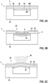
- Fig. 2A to 2C show schematic cross-sections of another ultrasound transducing device operated to transmit ultrasound waves.
- the ultrasound transducing device also comprises a carrier device 1 which has one cavity 2 limited by a floor element 13 (without a first metal layer 31 in this embodiment) and comprising an opening 22.
- the opening 22 is covered by a flexible membrane element 3 being configured and provided to oscillate.
- the membrane element 3 comprises a metal layer 32 on an upper surface and a metal layer 33 on a bottom surface being opposite of the upper surface, which together form a capacitive arrangement or capacitor.
- a piezoelectric foil 30 is sandwiched between the metal layers 32, 33.
- Such a device is known as a Piezoelectric Micro-machined Ultrasound Transducer (PMUT) and it is known to use inorganic piezoelectric materials such as AlN, PZT, etc. for the piezoelectric foil 30.
- PMUT Piezoelectric Micro-machined Ultrasound Transducer
- the dielectric element 10 of the carrier device 1 of a CMUT and PMUT is usually made of silicon or sapphire wherein the dielectric element 10 is manufactured using micromechanics processes on silicon or sapphire wafers with diameters of 4" to 6" inches.
- an electric voltage is applied between the both metal layers 32, 33, an internal field electric field E is generated between the metal layers 32, 33, and the piezoelectric foil 30 is deflected from an equilibrium position shown in Fig. 2A into a deflected position into the cavity 2 shown in Fig. 2B by an inverse piezoelectric effect.
- the membrane element 3 snaps back towards its equilibrium position and generates an ultrasound wave W that propagates into a direction away from the cavity 2 and into a medium such as tissue or water adjacent to the membrane element 3 as shown in Fig. 2C .
- the inverse piezoelectric effect causes a change in thickness ⁇ D 5 of the piezoelectric foil 30 which causes the deflection of the membrane element 3.
- the deflection is calculated as follows.
- the electric field E i and the mechanical stress ⁇ i are vectors and the piezoelectric coefficient d ij a tensor.
- An external pressure on the piezoelectric foil 30 may be constant and isostatic for a relevant period of time.
- the volume of the foil 30 may remain constant so that the change in thickness is followed by a corresponding change in extension of the foil 30 in a cross-section of the piezoelectric foil 30 normal to the surfaces 131, 132 having metal layers 32, 33 arranged on them.
- the piezoelectric foil 30 may take on a convex shape.
- the convex shape may be limited to a region area of a surface 131, 132 of the piezoelectric foil 30 where the metal layers 32, 33 are arranged.
- the change in length ⁇ D a is shown in Fig. 3 as an extension to the original length D a .
- the cross-section forms a circular segment with a radius r and an opening angle ⁇ .
- the radius r comprises a first portion of length X m which represents a distance between the piezoelectric foil 30 in its equilibrium position and its deflected position on a virtual line between an extremal point of the deflected piezoelectric foil 30 and a center of a circle of which the circular segment forms a portion of.
- a second portion of radius r is r - X m which represents the distance from the center to the piezoelectric foil at its equilibrium position along the virtual line between center and extremal point.
- the piezoelectric foil 30 may oscillate in a longitudinal mode, i.e., into and out of the cavity between a convex and a concave shape.
- this oscillation is shown to force the piezoelectric foil 30 on an arch around its equilibrium position (in and) out of the cavity.
- an arch in the cross-section may be viewed as an oscillation bulge of the piezoelectric foil 30 formed in a centre of the opening 22.
- the deflection distance from the equilibrium position may be characterized by X m in the centre of the bulge as explained above.
- a thickness D 5 of the piezoelectric foil 30 may, for example, be within 5 to 60 ⁇ m.
- a diameter of the cavity 2 corresponds to a diameter of the opening 22 covered by the membrane element 3 and may, for example, be between 30 to 250 ⁇ m.
- Suitable materials for use in the ultrasound transducing device will now be further characterized with respect to their physical properties of which the electromagnetic coupling factor is of particular interest.
- a ratio of sound characteristic impedances is Z .
- the sound characteristic impedances can also be understood as a (sound) wave resistance (corresponding to an analogy between mechanical and electrical waves).
- the sound characteristic resistance in a material is the ratio between particle velocity v and sound pressure p .
- the particle velocity corresponds to the electric current and the sound pressure to the voltage.
- a reflection at a boundary layer is given by the ratio of the sound pressures p Medium and p membrane .
- a conversion of energy from the applied electric voltage (i.e., electric energy W electric ) into sound energy in the ultrasound transducing device W foil can be described via an electromagnetic coupling factor k ij of which the component k 33 is of relevance for the present case if the oscillating portion of the piezoelectric foil is of a disc shape.
- the composite material has the best sound transducer properties. This is due to the high electromechanical coupling factor and, at the same time, low wave impedance, which leads to lower reflection at the interface between the piezoelectric foil 30 and the adjacent (aqueous) medium.
- a piezo-composite is made from a combination of a ceramic piezoelectric material such as PZT (lead zirconate titanite) with a polymer.
- the polymer may be an epoxy resin or a thermoplastic.
- the resulting material has a high piezoelectric coefficient and simultaneously an advantageous electromechanical coupling factor. Due to lower stiffness of such a material, the sound velocity is lower and the coupling to an aqueous medium is significantly better.
- the PZT composite has a desirably high acoustic impedance and may therefore be preferably used for ultrasound transducing device with high sensitivity.
- the very high FOM makes it an attractive choice for use in the membrane element.
- elements of the ultrasound transducing device may have the following properties.
- An ultrasound transducing device with such properties may be manufactured using printed circuit boards technology.
- Element (property) Lower limit Typical A Typical B
- Upper limit piezoelectric foil 30 (thickness D 5 ) 1 ⁇ m 10 ⁇ m 50 ⁇ m 0.5 mm Cavity (diameter D a ) 10 ⁇ m 50 ⁇ m 250 ⁇ m 0.5 mm Cavity (depth D c ) 10 ⁇ m 10 ⁇ m 25 ⁇ m 2 mm Cavity (capacitance C ) 7 femtoF 70 femtoF
- a depth D c of the cavity 2 may be a distance between the first and second metallic layer 31, 32 when the membrane element is in its equilibrium position (without an electric voltage applied).
- a capacitance C of the cavity 2 may be a capacitance of the capacitor formed by the first and second metallic layer 31, 32 over the cavity 2.
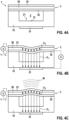
- Fig. 4A to 4C show schematic cross-sections of an ultrasound transducing device operated to transmit ultrasound waves.
- the ultrasound transducing device comprises a carrier device 1 with a body 10.
- the body 10 comprises one cavity 2 with a base 21 and an opening 22 and a floor element 13 limiting the base 21.
- the floor element comprises a first metal layer 31 and the opening 22 is covered by a flexible membrane element 3 being configured and provided to oscillate in order to transmit and/or receive ultrasound waves W.
- the membrane element 3 comprises a second metal layer 32 which may form a capacitive arrangement or capacitor with the first metal layer 31, wherein the first metal layer 31 and the second metal layer may be coupled by a first electrical field E 1 .
- the membrane element 3 comprises a third metal layer 33 and a piezoelectric foil 30 which is sandwiched between the second and the third metal layer 32, 33.
- the second metal layer 32 and the third metal layer 33 may form a capacitive arrangement or capacitor and be coupled by a second electrical field E 2 .
- the electrical field E 1 and E 2 are depicted by individual electrical field lines featuring only one arrowhead, respectively.
- a first capacitor may be formed over the cavity, and by the combination of the second and third metal layer 32, 33 a second capacitor may be formed over the piezoelectric foil 30. If an electric voltage U, V is applied to the first and second capacitor simultaneously, an oscillation of the membrane element 3, in particular, its convexity and its oscillation modes, may be controlled in order to transmit and/or receive ultrasound waves W.
- An advantage of such a setup combining capacitive control and piezoelectric control over the membrane element 3 is that the ultrasound transducing device may be operated more intricately.
- An electric field E 1 shown in Fig. 4B in the first capacitor exerts the following electric force F on the membrane element 3 when an electric voltage V is applied wherein V may vary in time as V(t).
- F ⁇ 0 ⁇ r A V t 2 D C 2
- Such a force may excite the membrane element 3 to oscillate wherein the piezoelectric foil 30 does not necessarily have to drive the oscillation - in principle an electric voltage U between the second and third metal layer 32, 33 may be zero.
- Fig. 4B shows an example with an electric voltage U applied so that an electric field E 2 is present in the second capacitor in addition to the electric field E 1 present in the first capacitor.
- the electric force F and the resulting sound pressure is calculated for an embodiment wherein the electric voltage V and additionally an electric voltage U are applied.
- a preferred mode of oscillation corresponds to a longitudinal oscillation of the membrane element 3 with a bulge forming at the center of the cavity 2 (which may have a cylindrical form).
- this mode is excited by applying electric voltage V, the membrane element 3 is elastically deflected by transverse contraction according to Poisson's ratio.
- a rather large electric voltage V is required to deflect the membrane element 3 to a degree required for transmission of ultrasound waves. If a membrane element 3 with a thickness below 5 ⁇ m is used, a smaller electric voltage V will be sufficient.
- an electric voltage U may be applied to the membrane element 3.
- the membrane element 3 may be excited to oscillate in the first mode resulting in the deflection X m shown in Fig. 5 .
- a sound pressure p E generated by the membrane element 3 may, for example, be amplified or, generally, be adjusted through the above calculated electric force F.
- Fig. 6 shows an embodiment of a control device 7 being configured and provided to apply and/or determine a first electric voltage V between the first and second metal layer 31, 32 and a second electric voltage U between the second and third metal layer 32, 33.
- the control device 7 may, for example, control the electric voltages U, V in order to achieve a sound pressure p E according to the above formula.
- the control device 7 may as well be operated to determine an electric voltage U, V resulting from a deflection of the membrane element 3.
- a significant deflection X m of the membrane element 3 from its equilibrium position may already be achieved with a static applied voltage U due to the inverse piezoelectric effect.
- a deflection in the range of a few microns may, for example, result from a 10 ⁇ m thick PVDF film as piezoelectric foil 30 over a cylindrically cavity 2 with a diameter of 250 ⁇ m.
- a cavity depth of, e.g., 20 ⁇ m With a cavity depth of, e.g., 20 ⁇ m, a high variance of electrostatic forces with a strong gradient towards the center arises due to the quadratic dependence of electric force on the distance X (F ⁇ 1/X(U(t)) 2 ).
- the strong gradient towards the center allows for driving a longitudinal oscillation of the membrane element 3 even with a small electric voltage V so that the ultrasound transducing device may be operated more efficiently.
- the control device 7 may, thus, be configured and provided to vary the first electric voltage V during a time interval in which the second electric voltage U is held static. Alternatively, the control device 7 may be configured and provided to vary the first and the second electric voltage V, U at the same time. This variation can be used to achieve an intensity modulation of the ultrasound wave W generated by the first electric voltage V via the second electric voltage U applied to the membrane element 3.
- the resonant frequency of the piezoelectric foil 30 with respect to its longitudinal oscillation depends on the second electric voltage U applied to the piezoelectric foil 30.
- different modes of operation can be used to generate the oscillation depending on the selected resonant frequency.
- Such modes may comprise frequency modulation and beam shaping.
- Fig. 7A and Fig. 7B show schematic cross-sections of an ultrasound transducing device operated to receive ultrasound waves.
- the ultrasound wave W is measured through the piezoelectric effect caused by a deflection of the membrane element 3 induced by the ultrasound wave W.
- Fig. 7A shows the arrival of an ultrasound wave W at an ultrasound transducing device.
- the ultrasound wave W is absorbed by the membrane element 3 and has deflected the membrane element 3 from its equilibrium position so that the piezoelectric foil 30 is deformed and second electric voltage U is measurable.
- the control device 7 may, thus, be further configured and provided to apply the first electric voltage V in order to drive an oscillation of the membrane element 3 and to concurrently determine the second electric voltage U to measure received ultrasound waves W.
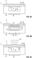
- Fig. 8A to 8C show schematic cross-sections of an ultrasound transducing device operated to transmit ultrasound waves W.
- Fig. 8A shows the device with its membrane element 3 in its equilibrium position.
- a second electric voltage U is applied to the second and the third metal layer 32, 33 so that the membrane element 3 is deflected from the equilibrium position to a deflected position due to the inverse piezoelectric effect acting on the piezoelectric foil 30.
- the membrane element 3 relaxes towards its equilibrium position.
- the membrane element 3 is snapped back from its deflected position beyond the equilibrium position forming an outward facing arch over the cavity 2 and thereby emits an ultrasound wave W.
- Fig. 9 shows a schematic cross-section in an exploded view of an ultrasound transducing device comprising two cavities 2.
- the two cavities 2 are formed in a body 10 such as a dielectric element of a carrier device 1, for example by means of mechanical deep milling, laser ablation or plasma etching.
- the carrier device 1 is formed by a printed circuit board having substrate formed from the dielectric element, more particular by a multilayered printed circuit board.
- the cavities 2 share a wall element 12 of the body 10, which is arranged between the two cavities 2.
- a membrane element 3 is arranged to cover the two cavities 2.
- One membrane element 3 may cover several cavities 2.
- the membrane element 3 has a piezoelectric foil 30 and a second and third metal layer 32, 33.
- the membrane element 3 is fixed to the carrier device 1 by an adhesive element 4.
- the adhesive element 4 comprises two openings 40 which are arranged to match the two cavities 2.
- the adhesive element 4 may be a pre-milled adhesive foil.
- a liquid adhesive may be used as an adhesive element 4 which is applied by screen printing or dispensing to either the piezoelectric foil 30 or the device carrier 2.
- the adhesive element 4 should also have sufficient electrical conductivity so that an electrical connection between the piezoelectric foil 30 and carrier device 1 may be established via the adhesive element 4.
- the carrier device 1, particularly the printed circuit board, comprises a plated via 34 arranged in via 11 of the body 10 to electrically connect the first and the second metal layer 31, 32.
- the second metal layer 32 may extend beyond a cavity so that it can be easily contacted.
- the carrier device 1 may further comprise an optional electronic assembly group 5.
- the electronic assembly group 5 may comprise an electronic device 50 such as microelectronic components, semiconductor devices, capacitors, and resistors.
- the electronic assembly group may be mounted on a back of the body 10 of the carrier device 1, particularly the printed circuit board, facing away from the cavities 2.
- the electronic assembly group 50 is mounted before arranging the membrane element 3 on the carrier device 1.
- the electronic device 50 comprises contact pads 51 that are connected electrically through a soldering connection 52 with the first metal layers 31.
- a potting compound or underfill 53 may enclose the contact pads 51, the soldering connection 52 and the first metal layers 31 for insulation.
- the carrier device 1 and the membrane element 3 are provided separately at first and then combined at a later stage.
Landscapes
- Engineering & Computer Science (AREA)
- Mechanical Engineering (AREA)
- Transducers For Ultrasonic Waves (AREA)
Priority Applications (2)
| Application Number | Priority Date | Filing Date | Title |
|---|---|---|---|
| EP23211067.6A EP4559588A1 (fr) | 2023-11-21 | 2023-11-21 | Dispositif de transduction ultrasonore |
| PCT/EP2024/083157 WO2025109098A1 (fr) | 2023-11-21 | 2024-11-21 | Dispositif de transduction ultrasonore |
Applications Claiming Priority (1)
| Application Number | Priority Date | Filing Date | Title |
|---|---|---|---|
| EP23211067.6A EP4559588A1 (fr) | 2023-11-21 | 2023-11-21 | Dispositif de transduction ultrasonore |
Publications (1)
| Publication Number | Publication Date |
|---|---|
| EP4559588A1 true EP4559588A1 (fr) | 2025-05-28 |
Family
ID=88920855
Family Applications (1)
| Application Number | Title | Priority Date | Filing Date |
|---|---|---|---|
| EP23211067.6A Pending EP4559588A1 (fr) | 2023-11-21 | 2023-11-21 | Dispositif de transduction ultrasonore |
Country Status (2)
| Country | Link |
|---|---|
| EP (1) | EP4559588A1 (fr) |
| WO (1) | WO2025109098A1 (fr) |
Citations (6)
| Publication number | Priority date | Publication date | Assignee | Title |
|---|---|---|---|---|
| US20040113524A1 (en) * | 2002-12-11 | 2004-06-17 | Baumgartner Charles E | Backing material for micromachined ultrasonic transducer devices |
| US20040190377A1 (en) * | 2003-03-06 | 2004-09-30 | Lewandowski Robert Stephen | Method and means for isolating elements of a sensor array |
| JP2007229328A (ja) * | 2006-03-03 | 2007-09-13 | Olympus Medical Systems Corp | マイクロマシンプロセスにより製造された超音波振動子、超音波振動子装置、その体腔内超音波診断装置、及びその制御方法 |
| CN106198724A (zh) * | 2016-06-30 | 2016-12-07 | 重庆大学 | 一种新型的多稳态超声检测传感器 |
| WO2021086184A1 (fr) * | 2019-10-30 | 2021-05-06 | Nederlandse Organisatie Voor Toegepast- Natuurwetenschappelijk Onderzoek Tno | Transducteur à membrane à largeur de bande améliorée |
| US20220314274A1 (en) * | 2019-08-21 | 2022-10-06 | Vermon Sa | Frequency-tunable ultrasonic device |
-
2023
- 2023-11-21 EP EP23211067.6A patent/EP4559588A1/fr active Pending
-
2024
- 2024-11-21 WO PCT/EP2024/083157 patent/WO2025109098A1/fr active Pending
Patent Citations (6)
| Publication number | Priority date | Publication date | Assignee | Title |
|---|---|---|---|---|
| US20040113524A1 (en) * | 2002-12-11 | 2004-06-17 | Baumgartner Charles E | Backing material for micromachined ultrasonic transducer devices |
| US20040190377A1 (en) * | 2003-03-06 | 2004-09-30 | Lewandowski Robert Stephen | Method and means for isolating elements of a sensor array |
| JP2007229328A (ja) * | 2006-03-03 | 2007-09-13 | Olympus Medical Systems Corp | マイクロマシンプロセスにより製造された超音波振動子、超音波振動子装置、その体腔内超音波診断装置、及びその制御方法 |
| CN106198724A (zh) * | 2016-06-30 | 2016-12-07 | 重庆大学 | 一种新型的多稳态超声检测传感器 |
| US20220314274A1 (en) * | 2019-08-21 | 2022-10-06 | Vermon Sa | Frequency-tunable ultrasonic device |
| WO2021086184A1 (fr) * | 2019-10-30 | 2021-05-06 | Nederlandse Organisatie Voor Toegepast- Natuurwetenschappelijk Onderzoek Tno | Transducteur à membrane à largeur de bande améliorée |
Also Published As
| Publication number | Publication date |
|---|---|
| WO2025109098A1 (fr) | 2025-05-30 |
Similar Documents
| Publication | Publication Date | Title |
|---|---|---|
| JP7108625B2 (ja) | 圧電トランスデューサを有するイメージング・デバイス | |
| Muralt et al. | Piezoelectric micromachined ultrasonic transducers based on PZT thin films | |
| Onitsuka et al. | Metal-ceramic composite transducer, the" moonie" | |
| US8542852B2 (en) | Electro-mechanical transducer, an electro-mechanical converter, and manufacturing methods of the same | |
| Eccardt et al. | Micromachined ultrasound transducers with improved coupling factors from a CMOS compatible process | |
| Dausch et al. | Theory and operation of 2-D array piezoelectric micromachined ultrasound transducers | |
| US9925561B2 (en) | Capacitive micromachined ultrasonic transducer with multiple deflectable membranes | |
| CN1283547C (zh) | 减少声能横向传播的微加工的超声换能器和方法 | |
| Eccardt et al. | Micromachined transducers for ultrasound applications | |
| CN116600907B (zh) | 超声换能器阵列器件 | |
| US12440868B2 (en) | Frequency-tunable ultrasonic device | |
| US20100201222A1 (en) | Ultrasound Transducer Manufactured by Using Micromachining Process, its Device, Endoscopic Ultrasound Diagnosis System Thereof, and Method for Controlling the Same | |
| CN1535243A (zh) | 微加工的超声换能器阵列 | |
| US20220169497A1 (en) | Micromechanical device for transducing acoustic waves in a propagation medium | |
| JP6860470B2 (ja) | 超音波センサ | |
| Jia et al. | Design and Characterization of a Sc 20% Al 1-20% N-Based PMUTs Array for an Underwater Communication System | |
| EP1980209A1 (fr) | Sonde a ultrasons | |
| JP5026770B2 (ja) | 超音波探触子及び超音波診断装置 | |
| WO2025109098A1 (fr) | Dispositif de transduction ultrasonore | |
| EP3733311A1 (fr) | Actionnement de structures piézoélectriques à l'aide de films minces ferroélectriques ayant plusieurs éléments | |
| US20240159583A1 (en) | Flexible, piezoelectric, miniaturized vibration sensor for machine integration | |
| US11039255B2 (en) | Wide-passband capacitive vibrating-membrane ultrasonic transducer | |
| De Cicco et al. | A new ultrasonic composite transducer implemented with thick film technology | |
| Coppa et al. | Building CMUTs for imaging applications from top to bottom | |
| Dausch et al. | 11F-3 Performance of flexure-mode pMUT 2D arrays |
Legal Events
| Date | Code | Title | Description |
|---|---|---|---|
| PUAI | Public reference made under article 153(3) epc to a published international application that has entered the european phase |
Free format text: ORIGINAL CODE: 0009012 |
|
| STAA | Information on the status of an ep patent application or granted ep patent |
Free format text: STATUS: THE APPLICATION HAS BEEN PUBLISHED |
|
| AK | Designated contracting states |
Kind code of ref document: A1 Designated state(s): AL AT BE BG CH CY CZ DE DK EE ES FI FR GB GR HR HU IE IS IT LI LT LU LV MC ME MK MT NL NO PL PT RO RS SE SI SK SM TR |
|
| STAA | Information on the status of an ep patent application or granted ep patent |
Free format text: STATUS: REQUEST FOR EXAMINATION WAS MADE |
|
| 17P | Request for examination filed |
Effective date: 20251128 |