EP4559590A1 - Appareil de nettoyage à haute pression - Google Patents
Appareil de nettoyage à haute pression Download PDFInfo
- Publication number
- EP4559590A1 EP4559590A1 EP23211447.0A EP23211447A EP4559590A1 EP 4559590 A1 EP4559590 A1 EP 4559590A1 EP 23211447 A EP23211447 A EP 23211447A EP 4559590 A1 EP4559590 A1 EP 4559590A1
- Authority
- EP
- European Patent Office
- Prior art keywords
- pressure
- operating element
- cleaning device
- pressure value
- main line
- Prior art date
- Legal status (The legal status is an assumption and is not a legal conclusion. Google has not performed a legal analysis and makes no representation as to the accuracy of the status listed.)
- Pending
Links
Images


Classifications
-
- B—PERFORMING OPERATIONS; TRANSPORTING
- B08—CLEANING
- B08B—CLEANING IN GENERAL; PREVENTION OF FOULING IN GENERAL
- B08B3/00—Cleaning by methods involving the use or presence of liquid or steam
- B08B3/02—Cleaning by the force of jets or sprays
- B08B3/026—Cleaning by making use of hand-held spray guns; Fluid preparations therefor
-
- B—PERFORMING OPERATIONS; TRANSPORTING
- B05—SPRAYING OR ATOMISING IN GENERAL; APPLYING FLUENT MATERIALS TO SURFACES, IN GENERAL
- B05B—SPRAYING APPARATUS; ATOMISING APPARATUS; NOZZLES
- B05B12/00—Arrangements for controlling delivery; Arrangements for controlling the spray area
- B05B12/002—Manually-actuated controlling means, e.g. push buttons, levers or triggers
-
- B—PERFORMING OPERATIONS; TRANSPORTING
- B05—SPRAYING OR ATOMISING IN GENERAL; APPLYING FLUENT MATERIALS TO SURFACES, IN GENERAL
- B05B—SPRAYING APPARATUS; ATOMISING APPARATUS; NOZZLES
- B05B9/00—Spraying apparatus for discharge of liquids or other fluent material, without essentially mixing with gas or vapour
- B05B9/03—Spraying apparatus for discharge of liquids or other fluent material, without essentially mixing with gas or vapour characterised by means for supplying liquid or other fluent material
- B05B9/04—Spraying apparatus for discharge of liquids or other fluent material, without essentially mixing with gas or vapour characterised by means for supplying liquid or other fluent material with pressurised or compressible container; with pump
- B05B9/0403—Spraying apparatus for discharge of liquids or other fluent material, without essentially mixing with gas or vapour characterised by means for supplying liquid or other fluent material with pressurised or compressible container; with pump with pumps for liquids or other fluent material
-
- B—PERFORMING OPERATIONS; TRANSPORTING
- B08—CLEANING
- B08B—CLEANING IN GENERAL; PREVENTION OF FOULING IN GENERAL
- B08B2203/00—Details of cleaning machines or methods involving the use or presence of liquid or steam
- B08B2203/02—Details of machines or methods for cleaning by the force of jets or sprays
- B08B2203/0205—Bypass pressure relief valves
-
- B—PERFORMING OPERATIONS; TRANSPORTING
- B08—CLEANING
- B08B—CLEANING IN GENERAL; PREVENTION OF FOULING IN GENERAL
- B08B2203/00—Details of cleaning machines or methods involving the use or presence of liquid or steam
- B08B2203/02—Details of machines or methods for cleaning by the force of jets or sprays
- B08B2203/027—Pump details
-
- B—PERFORMING OPERATIONS; TRANSPORTING
- B08—CLEANING
- B08B—CLEANING IN GENERAL; PREVENTION OF FOULING IN GENERAL
- B08B3/00—Cleaning by methods involving the use or presence of liquid or steam
- B08B3/02—Cleaning by the force of jets or sprays
- B08B3/026—Cleaning by making use of hand-held spray guns; Fluid preparations therefor
- B08B3/028—Spray guns
Definitions
- the invention relates to a high-pressure cleaning device comprising a connection for a liquid source, a high-pressure pump, a main line through which liquid can be conveyed from the connection to an ejection opening of the main line by means of the high-pressure pump, an operating element for specifying a pressure value for the pressure in the main line and a pressure adjustment device which adjusts the pressure in the main line according to the pressure value specified by the operating element.
- a high-pressure cleaning device in which the pressure in the pressure chamber of the high-pressure cleaning device can be adjusted in steps.
- an input unit is arranged on the gun of the high-pressure cleaning device.
- the input unit for the step-by-step adjustment of the pressure is designed separately from an actuating lever, which serves to open a valve in the main line of the high-pressure cleaning device. Water can only be sprayed from the gun of the high-pressure cleaning device when this main line valve is opened using the operating lever. A pressure level is selected using the input unit, and the main line valve is then opened using the operating lever.
- Adjusting the pressure level while fluid is being sprayed is only possible in an uncomfortable manner; during spraying, the operating lever is pressed with one finger, and either the other hand or the thumb must be used to adjust the pressure. One-handed operation of the high-pressure cleaning device is then difficult.
- the invention is based on the object of developing a generic high-pressure cleaning device in such a way that a comfortable adjustment of the pressure is possible.
- the main line of the high-pressure cleaning device has a suction chamber between the connection and the high-pressure pump.
- the main line has a pressure chamber between the high-pressure pump and the discharge opening.
- the pressure adjustment device has a bypass line with a bypass valve.
- the bypass line fluidically connects the pressure chamber to the suction chamber.
- a free cross-sectional area of the bypass line can be adjusted using the bypass valve.
- the pressure adjustment device adjusts the free cross-sectional area of the bypass valve depending on the pressure value specified by the control element.
- the control element is continuously adjustable along a travel path. A specific pressure value is specified by each position of the control element.
- the travel path of the control element has several directly adjacent travel ranges.
- the position of the travel ranges can depend on the direction in which the position of the control element is changed. However, it can also be provided that the position of the travel ranges is fixed and unchangeable.
- Each travel range encompasses several different positions of the control element. In each travel range, a single pressure value is specified by the control element. The pressure values of at least two travel ranges are different. In particular, the pressure values of at least three travel ranges are different.
- the travel range of the control element has a total length.
- the length of a travel range is at least 10%, advantageously at least 20%, in particular at least 30% of the total length of the travel range.
- the length of the travel range or travel range can be measured in degrees of an angle or as the actual distance traveled.
- each travel range comprises several different positions of the control element and a single pressure value is specified by the control element in each travel range, a certain amount of play in the control element is possible without specifying a change in pressure. This makes it easier for the operator to maintain a desired pressure over an extended period. But a change in pressure is also possible without any problems because the control element's travel range has several directly adjacent travel ranges and a single pressure value is specified by the control element in each travel range. To change from one pressure value to another, the operator simply has to move the control element a little further along the travel range. This can be done with the same finger. There is no need to change your grip or operate another control element to set a different pressure value.
- the pressure values in the travel ranges increase, in particular continuously, at least within a partial range of the travel along the travel, starting from a starting position of the partial range with a low pressure value to an end position of the partial range with a high pressure value.
- This enables intuitive operation of the operating lever. By pressing the operating lever more firmly, i.e. by covering a greater distance along the travel, a different, in particular higher, pressure value can be specified. By simply actuating the operating element, an increase in the specified pressure value is thus possible.
- the control element is preloaded from the end position of the high-pressure sub-range toward the initial position of the low-pressure sub-range. When the control element is released, a lower pressure value is specified due to the preload of the control element.
- the partial range extends over the entire travel of the control element. This allows the entire travel of the control element to be utilized for intuitive pressure value specification via the control element.
- the relationship between pressure values and travel ranges has a hysteresis, so that the division of the travel into the control value ranges depends on the pressure value specified by the operating element before entering a control value range.
- the division of the travel within the control value range depends on whether the operating element is moved towards the initial position or towards the end position. This prevents the pressure or pressure value from jumping back and forth after a transition from one pressure value to another. It also prevents the pressure adjustment device from setting different pressures when the operating element is positioned at the boundary between two adjacent travel ranges due to slight fluctuations in the operating element along the travel.
- the travel ranges each have an edge area.
- the control element specifies a larger pressure value or a smaller pressure value depending on which pressure value the control element specifies immediately before entering the edge area, in particular in the adjacent control value range.
- the control element specifies a larger pressure value or a smaller pressure value depending on whether the control element is moving towards the initial position or towards the end position. is moved.
- the control element in the edge area specifies the pressure value that it specified immediately before entering the edge area.
- the high-pressure cleaning device is designed so that the high-pressure pump operates at a constant power output, regardless of the position of the control element during operation of the high-pressure cleaning device.
- This enables even utilization of the high-pressure pump during operation of the high-pressure cleaning device.
- This enables gentle operation of the high-pressure cleaning device and the high-pressure pump.
- the free cross-sectional area of the bypass valve can be precisely adjusted depending on the pressure value specified by the control element.
- the inventive solution to the objective technical problem by the features of claim 7 provides that the operating element is continuously adjustable along a travel path. A specific pressure value is specified in each position of the operating element.
- the high-pressure cleaning device has a selector element for selecting at least two different, in particular at least three different characteristic curves, each with a different relationship between the position of the operating element and the pressure value. By selecting a characteristic curve using the selector element, the assignment of the position of the operating element and the pressure value can be set and/or changed. This allows the operator to select different characteristic curves for different applications. For example, a characteristic curve with a "rapid" pressure increase or one with a "fine-tuned” pressure increase can be selected.
- the operating element With a characteristic curve with a rapid pressure increase, the operating element only has to travel a short distance along the travel path of the operating element to already specify a high pressure value. With a fine-tuned characteristic curve, the pressure increase occurs only gradually along the travel path of the operating element. This provides the operator with an otherwise unchanged High-pressure cleaning equipment offers a completely different user experience. By selecting the characteristics, the operator can choose between aggressive or gentle cleaning of an object using the high-pressure cleaning equipment.
- the high-pressure cleaning device comprises a hand-operated ejection unit.
- the ejection opening is arranged on the hand-operated ejection unit.
- the selection element is advantageously arranged on the hand-operated ejection unit.
- the selection element is permanently attached to the hand-operated ejection unit. This allows the selection element to be operated conveniently.
- the operating element is arranged on the hand-held ejection unit.
- the selection element is arranged on the hand-held ejection unit in such a way that it can be operated by a user with the thumb of one hand while simultaneously holding a three-fingered finger of the same hand against the operating element. This allows the selection element to be operated easily and conveniently while the operating element is being actuated.
- different nozzles can be arranged at the ejection opening.
- the relationship between the position of the control element and the pressure value can be changed by selecting different characteristic curves using the selector, while maintaining the same nozzle arrangement at the ejection opening.
- a different characteristic curve can simply be selected using the selector. This does not require the placement of a different nozzle at the ejection opening.
- a second characteristic curve lies completely above a first characteristic curve, so that the second characteristic curve always specifies a higher pressure value than the first characteristic curve for the same position of the control element.
- the second characteristic curve can be described as more aggressive than the first characteristic curve.
- the first characteristic curve can be described as more sensitive than the second characteristic curve.
- the high-pressure cleaning device is designed so that, during operation of the high-pressure cleaning device, switching between the first characteristic curve and the second characteristic curve is possible by actuating the selector. This allows for convenient operation of the high-pressure cleaning device and the selector.
- all characteristic curves are free of intersection points with other characteristic curves.
- the pressure value assigned by a first characteristic curve is below a pressure value assigned by the second characteristic curve, for all other positions of the control element, the pressure values of the first characteristic curve are lower than the pressure values of the second characteristic curve for the same position of the control element.
- At least two, in particular at least three, characteristic curves have different gradients, at least in certain sections.
- gradient in this context is not to be understood in a strictly mathematical sense. Rather, it means that, at least on average, a different change in the specified pressure value is achieved for the same travel distance of the control element. This also causes the operator to perceive a characteristic curve with a steep gradient as aggressive and a characteristic curve with a shallow gradient as delicate.
- the control element has an initial position.
- the pressure value specified in the initial position varies depending on the characteristic curve selected using the selector. This allows a characteristic curve to have a high or low pressure value even in the initial position.
- a high pressure value in the initial position a high pressure value can be specified quickly by the control element without the control element having to be pressed hard or travel a large distance along the travel path. In this way, For a characteristic curve with a high pressure value in the initial position, fast cleaning with high pressure is possible.
- the control element has an end position.
- the control element has a boost position.
- the control element passes through the end position before the boost position along the travel, starting from the initial position.
- the pressure value specified by the control element increases abruptly when transitioning from the end position to the boost position. In particular, this can be provided for each characteristic curve. However, it can also be provided that this is only provided for one or part of the characteristic curves. This can give the user the feeling of a boost at the end of the characteristic curve.
- a maximum pressure value can be transmitted from the control element. In this way, the pressure adjustment device can set and achieve the greatest pressure in the main line when the control element is actuated to its maximum.
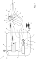
- Fig. 1 shows a high-pressure cleaning device 1.
- the high-pressure cleaning device 1 is used to spray a cleaning fluid pressurized by the high-pressure cleaning device 1.
- the high-pressure cleaning device 1 comprises a pump unit 18 and an ejection unit 14.
- the ejection unit 14 is manually operable during normal use of the high-pressure cleaning device 1.
- the pump unit 18 and the ejection unit 14 are fluidically connected to one another via a main line 5.
- the ejection unit 14 consists of a gun.
- the ejection unit comprises a gun and a lance.
- the high-pressure cleaning device 1 includes a connection 2 for a fluid source 17.
- the fluid source 17 is an external fluid source.
- the external fluid source is the faucet of a domestic water supply. It can also be provided that the fluid source is an integral part of the high-pressure cleaning device.
- the high-pressure cleaning device 1 comprises an ejection opening 6.
- the high-pressure cleaning device 1 comprises the main line 5.
- the main line 5 of the high-pressure cleaning device 1 fluidically connects the connection 2 to the ejection opening 6.
- the connection 2 is arranged on the pump unit 18.
- the ejection opening 6 is arranged on the ejection unit 14.
- the ejection opening 6 is arranged on the ejection unit 14, which is designed as a pistol.
- the ejection opening is arranged on an exchangeable lance of the ejection unit.
- the high-pressure cleaning device 1 comprises a high-pressure pump 3.
- liquid can be conveyed through the main line 5 from the connection 2 to the ejection opening 6.
- the liquid source 17 supplies liquid to the main line 5.
- the high-pressure pump 3 is arranged in the main line 5.
- the high-pressure pump 3 pressurizes the liquid.
- the cleaning liquid can be pressurized to a pressure of at least 10 bar, in particular of at least 15 bar, in particular of at least 30 bar, in particular of at least 100 bar.
- the high-pressure pump 3 can pressurize the cleaning liquid to a maximum of 600 bar, in particular of a maximum of 500 bar.
- the high-pressure pump 3 is arranged between a suction chamber 9 and a pressure chamber 10 of the main line 5.
- the main line has the suction chamber 9 between the connection 2 and the high-pressure pump 3.
- the main line 5 has the pressure chamber 10 between the high-pressure pump 3 and the ejection opening 6.
- the suction chamber 9 is formed by a section of the main line 5 between the connection 2 and the high-pressure pump 3.
- the pressure chamber 10 is formed by a section of the main line 5 between the high-pressure pump 3 and the ejection opening 6.
- the high-pressure pump 3 conveys liquid from the suction chamber 9 to the pressure chamber 10.
- the suction chamber 9 and the pressure chamber 10 are part of the main line 5. Downstream of the high-pressure pump 3, the pressure in the main line 5 is greater than upstream of the high-pressure pump 3.
- the high-pressure pump 3 is designed separately from the ejection unit 11.
- Various ejection units can be connected to the high-pressure pump 3.
- the high-pressure cleaning device 1 has a motor 61.
- the motor 61 is arranged in the pump unit 18.
- the motor 61 can be designed as a brushless DC motor.
- a brushless DC motor is also referred to as an EC motor.
- the motor can also be a universal motor.
- the motor 61 is an induction motor. In an induction motor, a rotating magnetic field of the stator sets the rotor in motion.
- the induction motor in the exemplary embodiment is operated with alternating current.
- the voltage source can be provided, for example, by the mains voltage. If battery or rechargeable battery operation is provided, the motor can also be a brushless DC motor. In this case, the rechargeable battery can be provided as a component of the high-pressure cleaning device 1.
- the high-pressure cleaning device 1 comprises a main switch 19.
- the main switch 19 serves to interrupt the power supply of the entire high-pressure cleaning device 1, in particular the motor 66.
- the main switch 19 is arranged on the pump unit 18.
- the high-pressure cleaning device 1 comprises a main line valve 62.
- the main line valve 62 is arranged in the main line 5.
- the main line valve 62 has two valve states.
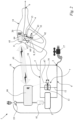
- the two valve states include a closed state ( Fig. 1 ) and an open state ( Fig. 2 ).
- the main line valve 62 allows liquid to flow through the main line 5.
- the main line valve 62 prevents liquid from flowing through the main line 5.
- liquid is sprayed out of the ejection opening 6.
- the closed state of the main line valve 62 no liquid is sprayed out of the ejection opening 6.
- the main line valve 62 is arranged in the ejection unit 14.
- the main line valve is arranged in the pump unit.
- the main line valve is arranged between the connection and the high-pressure pump.
- the high-pressure cleaning device 1 has an operating element 4.
- the operating element 4 is designed separately from the main switch 19.
- the operating element 4 is used to specify a Fig. 3 shown pressure value 31, 32, 33 for the pressure in the main line 5.
- the high-pressure cleaning device 1 comprises a pressure adjustment device 7.
- the pressure adjustment device 7 serves to adjust the pressure in the main line 5 according to the pressure value 31, 32, 33 specified by the control element 4.
- the control element 4 is arranged along a Fig. 2
- the actuating element 4 is continuously adjustable along the travel path 8 shown.
- Each position of the actuating element 4 along the travel path 8 corresponds to a specific pressure value 31, 32, 33.
- Each position of the actuating element 4 specifies a specific pressure value 31, 32, 33.
- the high-pressure cleaning device 1 is designed such that a pressure value 31, 32, 33 predetermined by a specific position of the control element 4 is transmitted to the pressure adjustment device 7.
- the pressure adjustment device 7 adjusts the pressure in the main line 5 according to this predetermined pressure value 31, 32, 33.
- the pressure adjustment device 7 comprises a bypass line 12.
- the bypass line 12 fluidically connects the pressure chamber 10 to the suction chamber 9.
- the bypass line 12 enables a further fluidic connection between the suction chamber 9 and the pressure chamber 10, separate from the fluidic connection between the suction chamber 9 and the pressure chamber 10 via the high-pressure pump 3.
- the pressure in the pressure chamber 10 is higher than in the suction chamber 9. Due to this pressure gradient, fluid can flow from the pressure chamber 10 into the suction chamber 9 through the bypass line 12.
- a bypass valve 13 is arranged in the bypass line 12.
- the bypass valve 13 is part of the pressure adjustment device 7.
- the free cross-sectional area of the bypass line 12 can be adjusted using the bypass valve 13. This allows the pressure in the pressure chamber 10 to be regulated. With a larger free cross-sectional area, the pressure equalization between the pressure chamber 10 and the suction chamber 9 occurs to a greater extent. If a high pressure is to prevail in the pressure chamber 10, the free cross-sectional area of the bypass line 12 is reduced using the bypass valve 13. The larger the free cross-sectional area of the bypass line 13, the greater the volume flow through the bypass line 13 during operation, with otherwise unchanged conditions.
- the bypass valve 13 can be adjusted in stages or continuously between a fully closed state and a fully open state. Between the fully closed state and the fully open state, the bypass valve 13 can have different degrees of closure. In the exemplary embodiment, the bypass valve 13 is continuously adjustable, at least in sections. It can also be provided that the bypass valve is continuously adjustable between the fully closed state and the fully open state without interruption.
- the size of the volume flow of the liquid in the main line, in particular in the pressure chamber 10 of the main line 5, can be adjusted.
- the more the bypass valve 13 is closed the smaller the free cross-sectional area of the bypass line 12.
- the more the bypass valve 13 is closed the greater the volume flow of the liquid in the main line 5.
- the more the bypass valve 13 is closed the greater the volume flow of the liquid in the main line 5 present at the ejection opening 6.
- the bypass valve 13 is adjustable using the control element 4. This serves to adjust the free cross-sectional area of the bypass line 12. By adjusting the bypass valve 13, the pressure in the main line 5, in particular in the pressure chamber 10, in particular at the discharge opening 6, can be regulated.
- the main line valve 62 can be switched between the open state and the closed state by means of the operating element 4.
- the operating element 4 is arranged on the injection unit 14.
- the operating element 4 can be used to switch the main line valve 62 between the open state and the closed state, and also to specify a pressure value 31, 32, 33 for the pressure adjustment device 7.
- the operating element 4 can be used to switch the main line valve 62 between the open state and the closed state, and also to adjust the bypass valve 13.
- the ejection unit 14 is movable relative to the pump unit 18.
- the main line 5 is configured as a flexible hose between the pump unit 18 and the ejection unit 16.
- the ejection opening 6 is arranged on the ejection unit 14.
- the ejection unit 14 can be directed with its ejection opening 6 toward an object to be cleaned.
- the ejection unit 14 is manually operable during the intended use of the high-pressure cleaning device 1.
- Control element 4 is arranged on the ejection unit 14. A user can guide the ejection unit 14 with one hand and simultaneously operate the control element 4 with the same hand.
- the hand-held ejection unit 14 has a handle area.
- the operating element 4 is arranged in the handle area.
- the high-pressure cleaning device 1 is designed such that a user can hold the hand-held ejection unit 14 by grasping the handle area with one hand and simultaneously actuate the operating element 4 with a finger of the same hand.
- the finger is the index finger. Actuation of the operating element 4 with the thumb is not provided in the exemplary embodiment.
- control element 4 specifies a pressure value 31, 32, 33.
- the control element 4 is continuously adjustable along the travel path 8. Each position of the control element 4 specifies a specific pressure value 31, 32, 33.
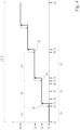
- the travel path 8 of the control element 4 has several directly adjacent travel ranges 21, 22, 23, which are Figures 3 and 4 In the example shown in the Figures 3 and 4
- the first travel range 21, the second travel range 22, and the third travel range 23 are shown as examples.
- the second travel range 22 lies between the first travel range 21 and the third travel range 23.
- the second travel range 22 is immediately adjacent to both the first travel range 21 and the third travel range 23.
- Each travel range 21, 22, 23 comprises several different positions 24, 25, 26 of the control element 4.
- the first position 24, the second position 25, and the third position 26 are marked as examples.
- a single pressure value 31, 32, 33 is specified by the control element 4.
- the pressure values 31, 32, 33 of at least two, in particular of at least three travel ranges 21, 22, 23 are different.
- Example according to the Figures 3 and 4 There are a total of five different travel ranges, each with different pressure values.
- the control element 4 specifies the same pressure value.
- the control element 4 specifies the second pressure value 32 in the first position 24. In the second position 25, the control element 4 also specifies the second pressure value 32. In the third position 26, the control element 4 also specifies the second pressure value 32. In the first travel range 21, the control element 4 specifies the first pressure value 31. Analogous to the second travel range 22, this is also the case in the first travel range 21 for at least three different positions of the control element 4. In the third travel range 23, the control element 4 specifies the third pressure value 33. Analogous to the second travel range 22, this is also the case in the third travel range 23 for at least three different positions of the control element 4.
- the control element 4 has a Fig. 1
- the control element 4 has a Fig. 2 fully actuated state shown. In the fully actuated state, the operating element 4 is deflected to its maximum extent. The operating element 4 is preloaded into the non-actuated state. A spring not shown in the figures can be used for this purpose.
- the travel 8 extends between the position assumed by the operating element 4 in the non-actuated state and the position assumed by the operating element 4 in the fully actuated state.
- the operating element 4 is a pivoting lever.
- the operating element 4 is Fig. 1
- the control element 4 can be pivoted about the pivot axis 20 shown.
- the control element 4 is pivoted through the maximum angle.
- the maximum angle is from 20° to 70°, in particular from 30° to 60°, in the exemplary embodiment from 40° to 50°.
- a travel range 21, 22, 23 extends over at least 10%, in particular over at least 15%. the extent of the travel 8.
- a travel range 21, 22, 23 covers at least an angular range of 10°, in particular of at least 5°.
- a travel range 21, 22, 23 extends over a maximum of 40%, in particular over a maximum of 30% of the extent of the travel 8.
- a travel range 21, 22, 23 covers a maximum angular range of 30°, in particular of a maximum of 20°.
- the pressure values 31, 32, 33 are of different sizes.
- the second pressure value 32 is greater than the first pressure value 31.
- the third pressure value 33 is greater than the second pressure value 32.
- the pressure values 31, 32, 33 which are respectively assigned to the different travel ranges 21, 22, 23, take up along the travel range 8 starting from an initial position 41 ( Fig. 1 ) to a final position 42 ( Fig. 2 ) of the operating element 4, in particular with regard to different travel ranges 21, 22, 23, increases continuously.
- the initial position 41 is assigned a low pressure value 31.
- the end position 42 is assigned a high pressure value 40.
- the partial range 27 extends over the entire travel range 8 of the operating element 4.
- the initial position 41 corresponds to the position of the operating element 4 in the unactuated state.
- the end position 42 corresponds to the position of the operating element 4 in the fully actuated state.
- the partial range 27 extends only over part of the travel range 8 of the operating element 4.
- the high-pressure cleaning device 1 comprises a Figures 1 and 2
- the detector 15 is designed to detect a position of the operating element 4.
- the position of the operating element 4 is also referred to as the adjustment position.
- the detector 15 can detect any position of the operating element 4 within the adjustment range 8. It can be provided that the detector 15 is a Hall sensor. In the exemplary embodiment, the detector 15 is a potentiometer.
- the operating element 4 and The detector 15 is arranged on the ejection unit 14 in such a way that the adjustment position of the control element 4 can be detected.
- the control element 4 interacts with the detector 15.
- the high-pressure cleaning device 1 is designed such that the pressure adjustment device 7 adjusts the pressure in the main line 5, in particular in the pressure chamber 10 of the main line 5, depending on the position of the operating element 4 along the adjustment path 8.
- the high-pressure cleaning device 1 is designed such that the bypass valve 13 of the pressure adjustment device 7 adjusts the size of the free cross-sectional area of the bypass line 12 depending on the adjustment position of the operating element 4.
- the detector 15 detects the position of the operating element 4 and generates a signal, based on which the bypass valve 13 is adjusted. Part of this signal in the exemplary embodiment is an initial signal 64 ( Figures 1 and 2 ).
- the initial signal 64 is generated by the detector 15 and forwarded to a transmitting unit 63.
- the initial signal 64 is an electrical signal.
- the initial signal 64 is forwarded to the transmitting unit 63 by means of a signal line, in the exemplary embodiment by means of a power cable. It can also be provided that an electrical or electromagnetic signal is used directly to forward the pressure value to the pressure setting device 7, in particular to the bypass valve 13. It can also be provided that the initial signal 64 is an electromagnetic signal.
- the transmitting unit 63 is arranged on the ejection unit 14. The pressure setting device 7 sets the pressure in the main line 5 according to the signal triggered by the operating element 4.
- the bypass valve 13 is adjustable by means of the signal triggered by the operating element 4.
- the signal can be transmitted wirelessly.
- an electromagnetic signal 65 is generated in the transmitting unit 63.
- the electromagnetic signal 65 is part of the signal emitted by the operating element 4 for adjusting the pressure in the main line 5 by means of the pressure adjusting device 7.
- the electromagnetic signal 65 is part of the Signal output from control element 4 for setting the free cross-sectional area of the bypass line 12.
- the high-pressure cleaning device 1 has a Figures 1 and 2
- the control unit 66 shown in FIG. 1 is arranged in the pump unit 18.
- the electromagnetic signal 65 is transmitted from the transmitting unit 63 to the control unit 66.
- the electromagnetic signal 65 received by the control unit 66 is used to adjust the pressure in the main line 5.
- the electromagnetic signal 65 received by the control unit 66 is used to adjust the free cross-sectional area of the bypass line 12 by means of the bypass valve 13.
- the bypass valve 13 is adjustable by means of a servomotor 16.
- the servomotor 16 is a component of the pressure adjustment device 7.
- the servomotor 16 is arranged in the pump unit 18.
- the bypass valve 13 can be adjusted such that the free cross-sectional area of the bypass line 12 can be adjusted.
- an end signal 67 is generated in the control unit 66, which is transmitted to the servomotor 16.
- the end signal 67 is transmitted electrically via a cable.
- the end signal is transmitted wirelessly.
- the end signal can be an electromagnetic signal.
- the end signal 67 is part of the signal emitted by the control element 4 for adjusting the pressure in the main line 5, in particular for adjusting the free cross-sectional area of the bypass line 12.
- the actuator 16 Based on the end signal 67, the actuator 16 adjusts the bypass valve 13.
- the bypass valve 13 can be adjusted such that a continuous adjustment of the size of the free cross-sectional area of the bypass line 12 is possible.
- the size of the free cross-sectional area can be continuously adjusted by means of the control element 4.
- the control element 4 is arranged on the ejection unit 14.
- the control element 4 is arranged in particular on the gun.
- the control element 4 is in the handle area arranged.
- the opening of the main line valve 62 by the operating element 4 can be effected mechanically. In the exemplary embodiment, however, this is also effected by a main line signal 68 sent from the detector 15 to the main line valve 62.
- this main line signal 68 is an electrical signal.
- the detector 15 generates the main line signal 68, which is transmitted to the main line valve 62.
- This main line signal 68 causes the main line valve 62 to be transferred from the closed state to the open state.
- the main line signal 68 still transmitted from the detector 15 to the main line valve 62 ensures that the main line valve 62 is in the open state, in particular in the fully open state.
- the high-pressure cleaning device 1 is designed such that, when the control element 4 is not actuated, the bypass valve 13 is adjusted so that the free cross-sectional area of the bypass line 12 is maximized.
- the high-pressure cleaning device 1 is structurally designed such that, before a reduction in the maximum free cross-sectional area of the bypass line 13 triggered by the control element 4, the main line valve 62 is switched from the closed state to the open state by means of the control element 4.
- the bypass valve 13 is opened only after the main line valve 62 has been opened.
- the high-pressure cleaning device 1 is designed such that, before the control element 4 is transferred from the actuated state of the control element 4 to the non-actuated state of the control element 4, the bypass valve 13 is adjusted such that the free cross-sectional area of the bypass line 12 is increased. Before the main line valve 62 is transferred from the open state to the closed state, the bypass valve 13 is at least partially opened.
- the operating element 4 can be adjusted along a travel path 8 from the unactuated position into positions with increasing distance from the unactuated position.
- the unactuated position corresponds to the initial position 41.
- the operating element 4 assumes the maximum distance from the unactuated position, or from the initial position 41, in the fully actuated position.
- the fully actuated position corresponds to the end position 42.
- the high-pressure cleaning device 1 is designed such that the bypass valve 13 reduces and/or at least does not increase the free cross-sectional area of the bypass line 12 as the distance of the operating element 4 from the initial position 41 increases.
- each travel range 21, 22, 23 comprises several different positions 24, 25, 26 of the control element 4, which are each assigned to a single pressure value 31, 32, 33 in the associated travel range 21, 22, 23, the cross-sectional area of the bypass line 12 is reduced in stages when the control element 4 is pressed.
- the pressure value 31, 32, 33 specified by the control element changes abruptly.
- the pressure in the main line 5, in particular in the pressure chamber 10 increases in stages.
- a smaller volume of the fluid pumped by the high-pressure pump 3 can flow back from the pressure chamber 10 into the suction chamber 9 via the bypass line 12.
- the pressure in the main line 5, in particular in the pressure chamber 10 is at its maximum for the open state of the main line valve 62.
- the high-pressure cleaning device 1 is designed such that the high-pressure pump 3 operates at a constant power regardless of the position of the control element 4 during operation of the high-pressure cleaning device 1. It is not the pumping power of the high-pressure pump 3 that is changed by the control element 4, but rather the free cross-sectional area of the bypass line 12. This allows for a particularly precise adjustment of the pressure in the main line 5, particularly in the pressure chamber 10.
- the pressure in the main line 5, particularly in the pressure chamber 10, is controlled by adjusting the bypass valve 13. This is achieved in a simple, uncomplicated, and cost-effective manner. In particular, this type of pressure adjustment allows the pressure to be adjusted independently of the type of motor 61 of the high-pressure pump 3.
- the distance of the operating element 4 to its unactuated position refers to the distance of a reference point on the operating element 4.
- the operating element 4 is a lever that can be pivoted about the pivot axis 20.
- the reference point is the point on the operating element 4 with the greatest distance from the pivot axis 20.
- the unactuated position of the operating element 4 is defined in the exemplary embodiment by the position of the reference point when the operating element 4 is unactuated.
- the operating element 4 When the operating element 4, designed as a lever, is actuated in the unactuated position of the operating element 4, the operating element 4—and thus also the reference point—is pivoted along the travel path 8.
- the travel path 8 is a circular segment.
- the distance of the operating element 7 from the unactuated position corresponds to the distance of the reference point from the unactuated position measured along the travel path 8 designed as a circular segment. It can also be provided to measure the distance in the form of an angular distance of the reference point from the unactuated position relative to a pivoting movement about the pivot axis 20.
- the operating element 4 is a single component that combines the functions of both actuating the main line valve and actuating the pressure adjustment device 7, in particular the bypass valve 13.
- the operating element 4 is a single piece.
- the operating element 4 can be operated with a single finger.
- the high-pressure cleaning device 1 is designed such that actuation of the operating element 4 by a user during use of the high-pressure cleaning device 1 is possible both for switching the main line valve 62 between the open state and the closed state and for specifying a pressure value 31, 32, 33 for the pressure adjustment device 7, in particular for adjusting the bypass valve 13, using only a single finger, namely the index finger, the middle finger, the ring finger or the little finger.
- the high-pressure cleaning device 1 is designed such that the actuation of the main line valve 62 for switching the main line valve 62 between the open state and the closed state and the actuation of the pressure adjustment device 7, in particular the actuation of the bypass valve 13 for adjusting the bypass valve 13, can be triggered by actuating the operating element 4 using a single continuous movement of a single finger.
- the main line valve 62 and then the pressure adjustment device 7, in particular the bypass valve 13 are actuated one after the other.
- the continuous movement occurs in the opposite direction. Accordingly, during the single continuous movement, the pressure adjustment device 7, in particular the bypass valve 13, and then the main line valve 62 are actuated one after the other.
- the detector 15 When the operating element 4 is moved along the travel path 8 starting from the unactuated position, the detector 15 initially detects a movement of the operating element 4 from the unactuated position. The detector 15 then sends the main line signal 68 to the main line valve 62, which is then transferred from the closed state to the open state. Only upon further movement of the operating element 4 along the travel path 8, i.e. upon further movement of the operating element 4, which is designed as a lever, from the unactuated position of the operating element 4, does the detector 15 send the initial signal 64 to the transmitting unit 63, based on which the pressure adjustment device 7 reduces the pressure in the main line 5, in particular in the pressure chamber 10. In particular, due to the initial signal 64, a reduction in the maximum free cross-sectional area of the bypass line 12 is effected by the bypass valve 13 and the actuator 16.
- the transition of the operating element 4 from the actuated state (i.e., from the non-deactuated state) to the deactuated state occurs in the reverse order.
- the pressure in the main line 5, in particular in the pressure chamber 10 is reduced by the pressure adjustment device 7.
- the free cross-sectional area of the bypass line 12 is initially increased by adjusting the bypass valve 13 using the servomotor 16.
- the relationship between the pressure values 31, 32, 33 and the travel ranges 21, 22, 23 exhibits a hysteresis.
- the division of the travel 8 of the control element 4 into the control value ranges 21, 22, 23 depends on which pressure value 31, 32, 33 the control element 4 specifies before entering the adjacent control value range 21, 22, 23.
- the division of the travel 8 into the control value ranges 21, 22, 23 depends on whether the control element 4 is moved towards the initial position 41 or towards the end position 42.
- the travel ranges 21, 22, 23 have edge areas 28, 29.
- the control element 4 In the edge areas 28, 29, the control element 4 outputs a pressure value 31, 32, 33 depending on which pressure value 31, 32, 33 the control element 4 has before entering the adjacent Depending on the travel range 21, 22, 23, in particular on whether the operating element 4 is moved towards the initial position 41 or towards the end position 42, a larger pressure value 32, 33 or a smaller pressure value 31, 32 is specified.
- Examples include Fig. 4 the edge areas 28 and 29 of the second travel range 22, or the second travel range 22', are shown.
- the travel range 8 is divided into the travel ranges 21, 22 and 23 when the operating element 4 is moved in the direction of the fully actuated position of the operating element 4, in the exemplary embodiment in the direction of the end position 42.
- the travel range 8 is divided into the travel ranges 21', 22' and 23'.
- the first travel ranges 21' and 21 overlap.
- the second travel ranges 22' and 22 overlap.
- the third travel ranges 23' and 23 overlap.
- Travel range 22' is assigned to travel range 22.
- Travel range 23' is assigned to travel range 23.
- Travel range 21' is smaller than travel range 21.
- Travel range 21 extends from the initial position 41.
- the travel range 21' extends from the initial position 41.
- the travel range 22' is shifted relative to the travel range 22 in the direction of the initial position 41.
- the travel range 22' is the same size as the travel range 22.
- the travel range 23' is shifted relative to the travel range 23 in the direction of the initial position 41.
- the travel range 23' is the same size as the travel range 23.
- the above description of the travel ranges 21, 22, 23 also applies analogously to the travel ranges 21', 22', 23'.
- the transition to the second travel range 22 occurs in a first upshift position 71 of the operating element 4.
- the operating element 4 no longer specifies the first pressure value 31, but rather the second pressure value 32.
- the second pressure value 32 is greater than the first pressure value 31. If the first upshift position 71 of the operating element 4 is present starting from the smaller, first pressure value 31, the limit of the first travel range 21 is defined by the first upshift position 71 of the operating element 4. However, if the second pressure value 32 is present, i.e.
- the operating element 4 is in the second travel range 22 and the operating element 4 is moved in the direction from the end position 42 towards the start position 41, the transition from the second travel range 22' to the first travel range 21', or into the first travel range 21, does not occur at the first upshift position 71 of the operating element 4, but at a first downshift position 74 of the operating element 4.
- the first downshift position 74 is closer to the start position 41 of the operating element 4 than the first upshift position 71 of the operating element 4. Therefore, if the operating element 4 specifies the second pressure value 32, i.e. is in the second travel range 22, and the operating element 4 is moved towards the start position 41, the first travel range 21 or 21' is not defined by the first upshift position 71, but by the first downshift position 74.
- the first travel range is then limited by the in Fig. 4 with 21' is given.
- the first pressure value 31 or the second pressure value 32 can be specified by the control element 4, depending on whether the control element 4 enters the edge region 28 starting from the second travel range 22 or starting from the first travel range 21'. After switching up from the first pressure value 31 to the second pressure value 32, this prevents the pressure value from immediately jumping back to the first pressure value 31 in the event of slight fluctuations in the control element 4. Conversely, this is the case in an analogous manner when switching down from the second pressure value 32 to the first pressure value 31.
- the edge regions 28, 29 amount to at least 2%, in the exemplary embodiment at least 5% of the extent of the associated travel range 21, 21', 22, 22', 23, 23'.
- the edge region 28 is assigned to the first travel range 21 or the second travel range 22'.
- the edge region 28 extends over at least 2%, in the exemplary embodiment over at least 5% of the first travel range 21.
- the edge region 29 is assigned to the second travel range 22 or the third travel range 23'.
- the edge region 29 extends over at least 2%, in particular over at least 5% of the extent of the second travel range 22.
- the description for the edge region 28 of the first travel range 21 applies analogously to the edge region 29 of the second travel range 22.
- the remaining travel ranges have an assigned edge region.
- Analogous to the edge region 28, the edge region 29 is delimited by a second downshift position 75 and a second upshift position 72 of the control element 4.
- the edge region 30 assigned to the third travel range 23 is delimited by a third downshift position 76 and a third upshift position 73.
- the second upshift position 72 is further away from the unactuated position of the control element 4 than the second downshift position 75 of the control element 4.
- the third upshift position 73 is further away from the unactuated position of the control element 4 than the third downshift position 76 of the control element 4.
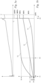
- Fig. 5a shows a diagram in which the position of the control element 4 is plotted on the abscissa axis (x-axis).
- the counterpressure that the control element 4 exerts on an operator is plotted on the ordinate axis (y-axis).
- the position s 0 plotted on the abscissa axis corresponds to the position in Fig. 1
- the position ss corresponds to the position shown in Fig. 2 shown fully actuated position of the control element 4.
- the control element 4 takes up the positions si, s 2 , s 3 or s 4.
- s 1 ⁇ s 2 Furthermore, s 1 ⁇ s 3 .
- the main line valve 62 In position s 0 , the main line valve 62 is closed. The bypass valve 13 is fully open. If the operator actuates the control element 4 in this situation, it first travels the distance from position s 0 to position s 1. At position s 1 , the main line valve 62 is opened. To do this, the operator must apply a force to overcome the counterpressure of the control element 4. The back pressure of the control element 4 increases along the path of the control element 4 from position s 0 to position s 1. At position s 1 of the control element 4, the main line valve 62 is open.
- the operating element 4 travels the distance from position s 1 to position s 2 .
- the pressure value specified by the operating element 4 is increased.
- the pressure value transmitted by the operating element 4 becomes greater.
- the pressure adjustment device 7 ensures that the bypass valve 13 is closed further.
- the volume flow in the main line 5 increases.
- the pressure in the main line 5 increases.
- the operating element 4 is preloaded into position s 0 .
- a spring presses the operating element 4 into position s 0 .
- the counterpressure on the operating element 4 increases slightly with increasing distance traveled by the operating element 4 due to the greater spring force.
- the range of travel of the control element 4 between positions s 3 and s 4 is linked to the activation of a boost function.
- the boost function provides an even greater volume flow and thus a greater pressure for the liquid in the main line 5, particularly in the pressure chamber 10 in the area of the ejection opening 6.
- the operator must first exert a greater force on the control element 4. If the operator continues to operate the control element 4 starting from position s 3 , the counterpressure on the control element 4 initially increases sharply. This increase in counterpressure is due to the design.
- the control element 4 must overcome a locking cam, which represents a resistance for the control element 4.
- control element 4 Due to the greater force required by the operator for this, the control element 4 covers the remaining distance to position s 4 very quickly and jerkily after overcoming the greatest counterpressure. Therefore, the flow rate increases very rapidly within this travel range of control element 4. The operator perceives this as a jump in the flow rate. A larger flow rate and thus also a higher pressure are suddenly available.
- the boost function is activated. After overcoming the greatest backpressure between positions s 3 and s 4 , the backpressure between positions s 4 and s 5 increases only moderately.
- control element 4 If the operator stops operating the control element 4 in position ss, the control element 4 is pushed back into position s0 by the spring. On the way of the control element 4 from position ss to position s0 , the main line valve 62 is closed in position s1 .
- the high-pressure cleaning device 1 comprises a selection element 11.
- the selection element 11 serves to select at least two different, in particular at least three different characteristic curves 51, 52, 53 ( Figures 5b and 6 ) with a different relationship between the position of the control element 4 and the pressure value 34, 35, 36.
- a characteristic curve 51, 52, 53 By means of the selector element 11, the assignment of positions 24, 25, 26 of the control element 4 and pressure values 34, 35, 36 can be adjusted.
- a characteristic curve 51, 52, 53 by means of the selector element 11, the assignment of positions 24, 25, 26 of the control element 4 and pressure values 34, 35, 36 can be changed. This is, for example, in Fig. 5b shown.
- a different pressure value 34, 35, 36 is present depending on which characteristic curve 51, 52, 53 is selected.
- the smallest pressure value 34 is assigned to the first characteristic curve 51.
- the middle pressure value 35 is assigned to the second characteristic curve 52.
- the largest pressure value 36 is assigned to the third characteristic curve 53. All pressure values 34, 35 and 36 are present at the same position 44 of the control element 4. If the first characteristic curve 51 is selected using the selection element 11, the smallest pressure value 34 is present at position 44 of the control element 4. If the second characteristic curve 52 is selected using the selection element 11, the second pressure value 35 is present at position 44 of the control element 4. If the third characteristic curve 53 is selected by means of the selection element 11, the highest pressure value 36 is present at position 44 of the control element 4.
- the high-pressure cleaning device 1 is designed such that the selection of a specific characteristic curve 51, 52, 53 is communicated to the control unit 66 by means of the selection element 11.
- the control unit 66 then links the position of the operating element 4, which is also communicated to it, with a predefined pressure value in accordance with the predefined characteristic curve 51, 52, 53.
- the linking of positions of the operating element along the travel 8 and the pressure value 34, 35, 36 predefined by the respective characteristic curve 51, 52, 53 takes place elsewhere, for example directly by the operating element 4.
- the characteristic curve 51, 52, 53 selected by the selection element 11 is transmitted to the control unit 66 by means of the transmitting unit 63.
- this takes place wirelessly by means of an electromagnetic signal 65.
- the pressure adjustment device 7 adjusts the pressure in the main line 5, particularly in the pressure chamber 10. In the exemplary embodiment, this is achieved by appropriately adjusting the free flow cross-section of the bypass line 12 by means of the bypass valve 13 and the servomotor 16. It can also be provided that the characteristic curves link the positions of the control element 4 not with different pressure values, but directly with a specific position of the bypass valve 13.
- the selection element 11 is arranged on the hand-operated ejection unit 14.
- the selection element 11 is arranged non-detachably on the hand-operated ejection unit 14.
- the selection element 11 is arranged on the hand-operated ejection unit 14 in such a way that the selection element 11 can be operated by a user with the thumb of one hand when, at the same time, a three-jointed finger of the same hand is resting on the operating element 4.
- Three-jointed fingers are the index finger, the middle finger, the ring finger, or the little finger. The thumb is not a three-jointed finger, but rather a two-jointed finger.
- the selection element 11 can be a digital component.
- the selection element 11 can have an interface to the operator for selecting the various characteristic curves 51, 52, 53.
- the interface can be designed in the form of a touchscreen. However, other interface designs, such as a mechanical rotary switch, are also conceivable.
- Various nozzles can be arranged at the discharge opening 6 of the high-pressure cleaning device 1.
- the assignment of positions 24, 25, 26 of the control element 4 and pressure values 31, 32, 33, 34, 35, 36 can be changed while maintaining the same nozzle arrangement at the discharge opening 6.
- the second characteristic curve 52 lies completely above the first characteristic curve 51.
- a higher pressure value 32 is always specified than with the first characteristic curve 51 for the same position of the control element 4.
- the third characteristic curve 53 lies completely above the second characteristic curve 52.
- the high-pressure cleaning device 1 is designed such that, during operation of the high-pressure cleaning device 1, in particular during operation of the motor 61 of the high-pressure pump 3, a change between the first characteristic curve 51 and the second characteristic curve 52, or between the second characteristic curve 52 and the third characteristic curve 53, is possible by actuating the selector element 11.
- the characteristic curves 52 and 53 shown have different gradients.
- the term "gradients" is not to be understood in a strictly mathematical sense. The increase in the pressure values depending on a specific, equal distance traveled along the travel 8 of the control element 4 differs due to the different gradients.
- the pressure value 37, 38, 39 specified in the unactuated position, in particular in the initial position 41 of the control element 4 varies depending on the characteristic curve 51, 52, 53 selected by means of the selection element 11.
- the first pressure value 37 assigned to the first characteristic curve 51 is smaller than the second pressure value 38 assigned to the second characteristic curve 52.
- the second pressure value 38 is smaller than the third pressure value 39 assigned to the third characteristic curve 53.
- the control element 4 has a boost position 43.
- the control element 4 passes along the travel path 8 starting from the initial position 41 and the end position 42 before the boost position 43.
- the pressure value specified by the control element 4 increases abruptly, as shown in Fig. 5b shown.
- the boost position 43 extends between the positions s 4 and s 5 Fig. 5a
- the bypass valve 13 is completely closed in the exemplary embodiment.
- a pressure value of 110% is indicated by a dashed line. This is symbolic and is intended to indicate that the high-pressure cleaner can be temporarily overloaded in the boost position 43 of control element 4.
Landscapes
- Cleaning By Liquid Or Steam (AREA)
Priority Applications (2)
| Application Number | Priority Date | Filing Date | Title |
|---|---|---|---|
| EP23211447.0A EP4559590A1 (fr) | 2023-11-22 | 2023-11-22 | Appareil de nettoyage à haute pression |
| US18/953,246 US20250161995A1 (en) | 2023-11-22 | 2024-11-20 | High pressure cleaning device |
Applications Claiming Priority (1)
| Application Number | Priority Date | Filing Date | Title |
|---|---|---|---|
| EP23211447.0A EP4559590A1 (fr) | 2023-11-22 | 2023-11-22 | Appareil de nettoyage à haute pression |
Publications (1)
| Publication Number | Publication Date |
|---|---|
| EP4559590A1 true EP4559590A1 (fr) | 2025-05-28 |
Family
ID=88923860
Family Applications (1)
| Application Number | Title | Priority Date | Filing Date |
|---|---|---|---|
| EP23211447.0A Pending EP4559590A1 (fr) | 2023-11-22 | 2023-11-22 | Appareil de nettoyage à haute pression |
Country Status (2)
| Country | Link |
|---|---|
| US (1) | US20250161995A1 (fr) |
| EP (1) | EP4559590A1 (fr) |
Citations (6)
| Publication number | Priority date | Publication date | Assignee | Title |
|---|---|---|---|---|
| DE3313249A1 (de) * | 1983-04-13 | 1984-10-25 | Woma-Apparatebau Wolfgang Maasberg & Co Gmbh, 4100 Duisburg | Hochdruckwasserstrahl-anlage |
| WO2016102075A1 (fr) | 2014-12-23 | 2016-06-30 | Alfred Kärcher Gmbh & Co. Kg | Appareil de nettoyage à haute pression |
| DE102017206504A1 (de) * | 2017-04-18 | 2018-10-18 | Robert Bosch Gmbh | Druckreinigungsvorrichtung mit einer Druckerzeugungseinheit |
| EP4079419A1 (fr) * | 2014-12-23 | 2022-10-26 | Alfred Kärcher SE & Co. KG | Appareil de nettoyage à haute pression |
| EP4115998A1 (fr) * | 2021-07-05 | 2023-01-11 | Andreas Stihl AG & Co. KG | Appareil de nettoyage haute pression |
| DE202014011605U1 (de) * | 2014-10-30 | 2023-04-04 | Alfred Kärcher SE & Co. KG | Hochdruckreinigungssystem |
-
2023
- 2023-11-22 EP EP23211447.0A patent/EP4559590A1/fr active Pending
-
2024
- 2024-11-20 US US18/953,246 patent/US20250161995A1/en active Pending
Patent Citations (6)
| Publication number | Priority date | Publication date | Assignee | Title |
|---|---|---|---|---|
| DE3313249A1 (de) * | 1983-04-13 | 1984-10-25 | Woma-Apparatebau Wolfgang Maasberg & Co Gmbh, 4100 Duisburg | Hochdruckwasserstrahl-anlage |
| DE202014011605U1 (de) * | 2014-10-30 | 2023-04-04 | Alfred Kärcher SE & Co. KG | Hochdruckreinigungssystem |
| WO2016102075A1 (fr) | 2014-12-23 | 2016-06-30 | Alfred Kärcher Gmbh & Co. Kg | Appareil de nettoyage à haute pression |
| EP4079419A1 (fr) * | 2014-12-23 | 2022-10-26 | Alfred Kärcher SE & Co. KG | Appareil de nettoyage à haute pression |
| DE102017206504A1 (de) * | 2017-04-18 | 2018-10-18 | Robert Bosch Gmbh | Druckreinigungsvorrichtung mit einer Druckerzeugungseinheit |
| EP4115998A1 (fr) * | 2021-07-05 | 2023-01-11 | Andreas Stihl AG & Co. KG | Appareil de nettoyage haute pression |
Also Published As
| Publication number | Publication date |
|---|---|
| US20250161995A1 (en) | 2025-05-22 |
Similar Documents
| Publication | Publication Date | Title |
|---|---|---|
| EP3344819B1 (fr) | Unité sanitaire | |
| EP3740708B1 (fr) | Dispositif d'actionnement de soupape | |
| DE102005019599B4 (de) | Steuerventilvorrichtung und Druckkreislauf | |
| EP4282546B1 (fr) | Appareil de nettoyage haute pression | |
| EP2580501B1 (fr) | Soupape d'inversion | |
| DE102013216395A1 (de) | Steuereinrichtung für hydraulische verstellpumpen und verstellpumpe mit einer steuereinrichtung | |
| EP3237124B1 (fr) | Appareil de nettoyage à haute pression | |
| EP1148251B1 (fr) | Soupape de commande de pression | |
| EP2212596A1 (fr) | Robinet à boisseau | |
| EP4559590A1 (fr) | Appareil de nettoyage à haute pression | |
| EP3688348B1 (fr) | Soupape de commutation sanitaire pouvant être commandée à distance et module sanitaire associé | |
| EP3939705A1 (fr) | Appareil de nettoyage haute pression | |
| EP4115998A1 (fr) | Appareil de nettoyage haute pression | |
| EP1502027B1 (fr) | Dispositif de regulation comprenant une soupape de regulation de valeur limite | |
| DE3320047C2 (fr) | ||
| DE69937729T2 (de) | Ventil zum aufteilen des durchflusses | |
| EP2672124A2 (fr) | Système hydraulique et vanne de limitation de pression | |
| DE102012211200A1 (de) | Greifinstrument | |
| DE3124944C2 (de) | "Hochdruckreiniger" | |
| DE102006050430A1 (de) | Handgeführtes Arbeitsgerät | |
| EP1974828A2 (fr) | Dispositif de distribution de fluide | |
| DE102023101418A1 (de) | Hochdruckreinigungsgerät | |
| EP2756197B1 (fr) | Ensemble soupape à fluide comprenant une soupape à fluide bistable | |
| DE69614554T3 (de) | Vorrichtung zur Kontrolle der Dampfströmung in dampfgebrauchenden elektrischen Haushaltsgeräten | |
| EP4208125A1 (fr) | Injecteur pour lentille intraoculaire |
Legal Events
| Date | Code | Title | Description |
|---|---|---|---|
| PUAI | Public reference made under article 153(3) epc to a published international application that has entered the european phase |
Free format text: ORIGINAL CODE: 0009012 |
|
| STAA | Information on the status of an ep patent application or granted ep patent |
Free format text: STATUS: THE APPLICATION HAS BEEN PUBLISHED |
|
| AK | Designated contracting states |
Kind code of ref document: A1 Designated state(s): AL AT BE BG CH CY CZ DE DK EE ES FI FR GB GR HR HU IE IS IT LI LT LU LV MC ME MK MT NL NO PL PT RO RS SE SI SK SM TR |
|
| STAA | Information on the status of an ep patent application or granted ep patent |
Free format text: STATUS: REQUEST FOR EXAMINATION WAS MADE |
|
| 17P | Request for examination filed |
Effective date: 20251126 |