EP4559620A1 - Tour multibroches à commande numérique avec plusieurs broches orientables - Google Patents
Tour multibroches à commande numérique avec plusieurs broches orientables Download PDFInfo
- Publication number
- EP4559620A1 EP4559620A1 EP24213695.0A EP24213695A EP4559620A1 EP 4559620 A1 EP4559620 A1 EP 4559620A1 EP 24213695 A EP24213695 A EP 24213695A EP 4559620 A1 EP4559620 A1 EP 4559620A1
- Authority
- EP
- European Patent Office
- Prior art keywords
- carriage
- translation axis
- lathe
- base
- parallel
- Prior art date
- Legal status (The legal status is an assumption and is not a legal conclusion. Google has not performed a legal analysis and makes no representation as to the accuracy of the status listed.)
- Pending
Links
Images


Classifications
-
- B—PERFORMING OPERATIONS; TRANSPORTING
- B23—MACHINE TOOLS; METAL-WORKING NOT OTHERWISE PROVIDED FOR
- B23Q—DETAILS, COMPONENTS, OR ACCESSORIES FOR MACHINE TOOLS, e.g. ARRANGEMENTS FOR COPYING OR CONTROLLING; MACHINE TOOLS IN GENERAL CHARACTERISED BY THE CONSTRUCTION OF PARTICULAR DETAILS OR COMPONENTS; COMBINATIONS OR ASSOCIATIONS OF METAL-WORKING MACHINES, NOT DIRECTED TO A PARTICULAR RESULT
- B23Q39/00—Metal-working machines incorporating a plurality of sub-assemblies, each capable of performing a metal-working operation
- B23Q39/04—Metal-working machines incorporating a plurality of sub-assemblies, each capable of performing a metal-working operation the sub-assemblies being arranged to operate simultaneously at different stations, e.g. with an annular work-table moved in steps
-
- B—PERFORMING OPERATIONS; TRANSPORTING
- B23—MACHINE TOOLS; METAL-WORKING NOT OTHERWISE PROVIDED FOR
- B23Q—DETAILS, COMPONENTS, OR ACCESSORIES FOR MACHINE TOOLS, e.g. ARRANGEMENTS FOR COPYING OR CONTROLLING; MACHINE TOOLS IN GENERAL CHARACTERISED BY THE CONSTRUCTION OF PARTICULAR DETAILS OR COMPONENTS; COMBINATIONS OR ASSOCIATIONS OF METAL-WORKING MACHINES, NOT DIRECTED TO A PARTICULAR RESULT
- B23Q39/00—Metal-working machines incorporating a plurality of sub-assemblies, each capable of performing a metal-working operation
- B23Q2039/002—Machines with twin spindles
-
- B—PERFORMING OPERATIONS; TRANSPORTING
- B23—MACHINE TOOLS; METAL-WORKING NOT OTHERWISE PROVIDED FOR
- B23Q—DETAILS, COMPONENTS, OR ACCESSORIES FOR MACHINE TOOLS, e.g. ARRANGEMENTS FOR COPYING OR CONTROLLING; MACHINE TOOLS IN GENERAL CHARACTERISED BY THE CONSTRUCTION OF PARTICULAR DETAILS OR COMPONENTS; COMBINATIONS OR ASSOCIATIONS OF METAL-WORKING MACHINES, NOT DIRECTED TO A PARTICULAR RESULT
- B23Q39/00—Metal-working machines incorporating a plurality of sub-assemblies, each capable of performing a metal-working operation
- B23Q2039/006—Machines with multi-spindles
-
- B—PERFORMING OPERATIONS; TRANSPORTING
- B23—MACHINE TOOLS; METAL-WORKING NOT OTHERWISE PROVIDED FOR
- B23Q—DETAILS, COMPONENTS, OR ACCESSORIES FOR MACHINE TOOLS, e.g. ARRANGEMENTS FOR COPYING OR CONTROLLING; MACHINE TOOLS IN GENERAL CHARACTERISED BY THE CONSTRUCTION OF PARTICULAR DETAILS OR COMPONENTS; COMBINATIONS OR ASSOCIATIONS OF METAL-WORKING MACHINES, NOT DIRECTED TO A PARTICULAR RESULT
- B23Q39/00—Metal-working machines incorporating a plurality of sub-assemblies, each capable of performing a metal-working operation
- B23Q2039/008—Machines of the lathe type
Definitions
- the present invention relates to the field of numerically controlled machine tools. More in particular, the invention relates to the field of numerical control lathes. Embodiments described herein relate to multiple lathes, with a plurality of pairs of headstocks and tailstocks for the simultaneous machining of a plurality of identical pieces.
- the lathe is specifically designed for machining pieces made of wood, light alloy, synthetic resin and the like.
- EP3858542 and EP4043146 disclose a numerically controlled multi-spindle lathe.
- EP2161098 discloses a multi-spindle milling machine.
- EP2161098 discloses a machine tool with a head carrying two spindles, which simultaneously machine pieces supported on two piece-holder tables adapted to rotate around parallel axes.
- the object of the present invention is to provide a numerically controlled multi-spindle lathe which allows greater flexibility in machining and which allows to execute a greater number of different machining operations on the pieces.
- a numerically controlled multi-spindle lathe according to the invention is defined in claim 1.
- Embodiments and further advantageous features of the lathe according to the invention are defined in the dependent claims.
- a numerically controlled multi-spindle lathe comprising a load-bearing structure having a base, extending along a first translation axis.
- the lathe further comprises a plurality of headstock and tailstock pairs which are coaxial with each other and each defining a respective rotation axis of the workpieces.
- each headstock is motorized.
- the distance between the headstocks and the tailstocks is adjustable.
- the rotation axes defined by each headstock/tailstock pair preferably lie on a common lying plane, which can be a vertical plane, for example. The rotation axes are appropriately parallel to the first translation axis.
- the lathe further comprises a first carriage guided along a first guide system, which can comprise guides integral with the base and extending in the direction of the first translation axis, which can be engaged by shoes integral with the first carriage.
- the first carriage is provided with a numerically controlled movement along the first translation axis.
- the lathe can comprise a second carriage, supported by the first carriage and movable with a numerically controlled movement with respect to the first carriage.
- the relative movement of the second carriage with respect to the first carriage occurs appropriately in the direction of a second translation axis, orthogonal to the first translation axis and also orthogonal to the lying plane of the rotation axes of the workpieces.
- the movement between the first carriage and the second carriage is enabled by a second guide system comprising guides and shoes.
- the second carriage extends over an upper face of the base.
- the first carriage can be positioned, at least in part, between the upper face of the base and the second carriage.
- the lathe comprises a plurality of spindles with parallel axes, which can be aligned with each other in particular according to a direction orthogonal to the first translation axis and to the second translation axis.
- the spindles are configured to engage and rotate tools configured to simultaneously machine pieces each mounted between a respective headstock/tailstock pair.
- the spindles can be carried by a rotatable support provided with a rotational movement around a rotation axis parallel to the alignment direction of the spindles and orthogonal to the first translation axis and the second translation axis.
- the spindles and the rotatable support form a rigid unit, in the sense that the rotation of the rotatable support around the rotation axis causes all the spindles to rotate simultaneously around such an axis, and that the spindles are connected to each other to form a single unit, such that the spindles cannot rotate with respect to each other around the rotation axis of the rotatable support.
- the rotation axis around which the rotatable support can rotate is appropriately a numerically controlled rotary axis.
- the rotatable support is rotatably supported on a slide constrained to the second carriage and provided with a translation movement, with respect to the second carriage.
- the relative movement between the second carriage and the slide occurs along a third translation axis, preferably orthogonal to the first translation axis and the second translation axis and parallel to the rotation axis of the rotatable support.
- the slide and the second carriage can be connected to each other by means of a third guide system, comprising guides and shoes, along which the relative movement between the slide and the second carriage occurs.
- the guides of the third guide system can be integral with the second carriage and the shoes can be integral with the slide, or vice versa.
- first translation axis and the second translation axis are horizontal
- the third translation axis is vertical
- the rotation axes of the headstocks and tailstocks are horizontal and can be superimposed on each other in a vertical direction, preferably coplanar on a vertical plane.
- vertical means a direction parallel to the direction of the force of gravity
- horizontal means a direction orthogonal to the vertical direction.
- the “vertical” and “horizontal” orientations refer to the position of the lathe when it is in operation.
- a multi-spindle lathe comprising a base along which a first carriage moves along a first numerically controlled translation axis.
- the first carriage carries a second carriage, which moves along a second numerically controlled translation axis, orthogonal to the first translation axis.
- the second carriage in turn carries a slide, on which a rotatable support is rotatably mounted.
- the latter carries a plurality of spindles.
- the rotatable support rotates around a numerically controlled rotary axis, parallel to a third numerically controlled translation axis, along which the slide moves with respect to the second carriage.
- the tools carried by the spindles supported by the rotatable support machine a plurality of pieces in parallel, brought into rotation by respective pairs of headstocks and tailstocks.
- the rotation axes of the pairs of headstocks/tailstocks are preferably coplanar and lie on a plane orthogonal to the second translation axis.
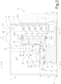
- FIG. 1 A first embodiment of a numerically controlled multi-spindle lathe according to the invention is illustrated in Figs. 1 to 4 .
- the lathe is indicated with 1 and comprises a load-bearing structure 3.
- the load-bearing structure 3 comprises a first upright 5 and a second upright 7.
- the uprights 5,7 are vertical and rigidly connected to a lower base 9. At their top the uprights 5 and 7 are connected to one another by a horizontal cross member 11.
- the base 9 can comprise a main body 9.1 and two arms 9.21, 9.22 which are parallel to each other and extend transversely to a longitudinal development of the main body 9.1.
- the main body 9.1 and the arms 9.21, 9.22 have coplanar lower surfaces and form a surface for resting on the floor of the base 9.
- the upper surfaces or faces of the arms 9.21, 9.22 can be at a lower height than the upper surface or face of the main body 9.1 of the base 9, as described in more detail hereafter.
- the lower ends of the uprights 5 and 7 are fixed to corresponding distal ends of the arms 9.21, 9.22.
- the base 9 has an upper surface or face 9.3, consisting of the upper face of the main body 9.1 of the base 9.
- the arms 9.21, 9.22 have respective upper faces 9.41 and 9.42 which can be located at a height h2 from the floor P, lower than the height h1, at which the upper face 9.3 of the main body 9.1 of the base 9 is located.
- the height h1 is also the highest height reached by the base 9.
- the lower ends of the uprights 5 and 7 are located at the height h2.
- Headstocks 13 are carried on the upright 5. Each headstock is associated with a tailstock 15. Each headstock 13 and respective tailstock 15 are coaxial with each other. The rotation axes of the headstock and tailstock pairs are indicated with A, which define support and rotation members of workpieces P.
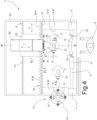
- the rotation axes A of the headstocks 13 and the tailstocks 15 lie on a common vertical plane of line Pc-Pc ( Fig.2 ).
- Each headstock 13 is rotated around the respective axis A by means of an electronically controlled motor, not shown.
- the motors of the headstocks 13 are preferably controlled so that all the headstocks 13 perform synchronous rotations, in the same direction or in opposite directions (clockwise and counter-clockwise).
- a plurality of tools U carried by a tool-holder spindles 31 (described in more detail hereafter and indicated simply as “spindles") can synchronously and simultaneously machine all the pieces P supported and rotated by the pairs of headstocks and tailstocks 13, 15.
- the tools U, and thus the spindles 31 carrying them rotate around mutually parallel axes.
- the spindles 31 are provided with a rotational movement around a vertical axis C, described hereafter, such that their rotation axes can be placed parallel to the rotation axes A of the headstocks 13 and tailstocks 15, or can be tilted at various angles in a horizontal plane.
- the rotation around the vertical rotary axis C can be restricted to an angle equal to or less than 270°, for example about 180-200°.
- the rotation axes A of the pairs of headstocks 13 and tailstocks 15 are parallel to a first numerically controlled translation axis X, along which the tools U move.
- the rotation axes A of the pairs of headstocks 13 and tailstocks 15 are also orthogonal to a second numerically controlled translation axis Y, along which the tools U move.
- the axes X and Y are described in more detail hereafter.
- the shape and arrangement of the spindles 31 with the respective tools U, and of the headstocks 13 and tailstocks 15 is such that the machining of the pieces P can occur with the rotation axes of the tools U and thus of the spindles 31 parallel to the rotation axes A of the headstocks 13 and of the tailstocks 15 and thus to the rotation axes of the workpieces P.
- the arrangement allows the pieces and the tools to cooperate with one another while the axes A are parallel to the rotation axes of the tools U and of the spindles 31 carrying them.
- the rotation around the axis C also allows the inclination of the rotation axes of the tools to be modified with respect to the rotation axes A of the workpieces P, thereby increasing the flexibility of the lathe 1 and allowing greater freedom in programming the work cycles and in the number of machining operations which can be carried out on the pieces P.
- the tailstocks 15 are supported by a load-bearing structure which allows the movement thereof in a direction parallel to the translation axis X to adjust the distance between the headstocks 13 and the tailstocks 15.
- the load-bearing structure comprises a movable upright 17 developing vertically.
- the movable upright 17 can be guided along an upper registration guide, or along a lower registration guide, or along two registration guides, respectively an upper guide and a lower guide.
- the movable upright 17 is guided along an upper registration guide, formed on or consisting of the crosspiece 11, and by a lower registration guide 19, which can preferably be integral with the base 9 and more precisely with the arms 9.21, 9.22.
- the lower registration guide 19 can be positioned at a height equal to or lower than the height at which the guide system 20 is located.
- the guides 11 and 19 are appropriately positioned so that their projection in plan is located between the arms 9.21 and 9.22 of the base 9.
- the movable upright 17 is integral with a slide 17.1 engaged with the guide constituted by the crosspiece 11, extending in the direction of the longitudinal development of the main body 9.1 of the base 9, i.e., parallel to the translation axis X. It is thereby possible to adapt the distance between all the headstocks 13 and the respective tailstocks 15 to the length of the workpieces P.
- the possibility of arranging the headstocks 13 on a movable upright and the tailstocks 15 on a fixed upright is not excluded, although the illustrated arrangement is preferable because the movable members (tailstocks 17) are free of power supply cables. It is also possible to create configurations in which both the headstocks 13 and the tailstocks 15 are carried by uprights which are both movable with respect to the load-bearing structure 3.
- the possibility of creating a simpler guide system for the movable upright 17 than that shown in the drawing, for example with a single guide, is not excluded.
- the movable upright 17 can be guided only by an upper guide or only by a lower guide.
- the guide is configured so as to give sufficient stability to the upright, for example it can comprise two rails or two guide profiles spaced from each other orthogonally to the direction of movement (parallel to X) of the movable upright 17.
- a first guide system 20 connects a first carriage or slide 23 to the base 9 and more precisely to the main body 9.1 of the base 9.
- the guide system 20 comprises a first pair of guides 21 and a set of shoes 24 slidably engaged with the guides 21.
- the guides 21 are integral with the main body 9.1 of the base 9 and the shoes 24 are integral with the carriage 23.
- the guides 21 can be fixed to the upper face 9.3 of the base 9, more specifically to the main body 9.1 of the base 9.
- the guides 21 extend parallel to the axis X and thus parallel to the longitudinal development of the main body 9.1 of the base 9.
- the guides 21 are spaced apart from each other in the direction of the second translation axis Y.
- the guides 21 are made from two distinct and separate tracks or profiles, fixed to a common element, in the case of the guides 21 such a common element being constituted by the main body 9.1 of the base 9.
- the guides can be made, for example, by means of a single component which has two opposite guide surfaces parallel to each other.
- the first carriage 23 is provided with a numerically controlled movement in the direction of the first translation axis X.
- the movement can be imparted by a linear electric motor, or by a rotary electric motor which drives a threaded rod meshing with a nut screw integral with the first carriage 23, for example.
- the first carriage 23 has a flattened configuration and extends generally in a horizontal direction, parallel to the upper face 9.3 of the main body 9.1 of the base 9.
- the first carriage 23 carries a second carriage 25, which is movable along the second translation axis Y.
- the second translation axis Y is horizontal and orthogonal to the first translation axis X.
- the second carriage 25 is placed above the first carriage 23 and therefore the first carriage 23 is interposed between the main body 9.1 of the base 9 and the second carriage 25.
- the second carriage 25 is preferably brought into a central position, i.e., symmetrical with respect to the first carriage 23.
- the first carriage 23 can have a vertical plane of symmetry MM and the second carriage 25 is placed in a centred position with respect to the plane of symmetry MM, so that such a plane is also the plane of symmetry of the second carriage 25.
- the plane of symmetry M-M is orthogonal to the first translation axis X and parallel to the second translation axis Y.
- the first carriage 23 and the second carriage 25 are connected to each other by a second guide system 26.
- the second guide system 26 comprises second guides 27 and respective shoes 29 slidably engaged with the second guides 27.
- the second guides 27 can be integral with the second carriage 25 and the respective shoes 29 can be integral with the first carriage 23.
- a reverse arrangement is not excluded, although in this case less advantageous.
- the spindles 31 are carried on the second carriage 25, on which the tools U can be engaged.
- the number of spindles 31 and the number of tools U is equal to the number of pairs of headstocks 13 and tailstocks 15 (in the example four tools U and respective spindles), but this is not essential.
- the number of spindles can be half the number of pairs of headstocks 13 and tailstocks 15. In such a case, a single tool works two pieces simultaneously in parallel.
- the spindles 31 can be rotated simultaneously by means of motors (not shown) in the same or different number with respect to the number of spindles 31. In the second case, appropriate multiple transmissions from a single motor to multiple spindles will be provided.
- the spindles 31 are supported on the second carriage 25 in the manner described hereafter. Thanks to the movements on the translation axes X and Y of the carriages 23, 25, the tools U can perform numerically controlled movements along the numerically controlled translation axis X to machine every point of the workpieces P held between the headstocks 13 and the tailstocks 15.
- the numerically controlled movement along the translation axis Y allows the tools U to be approached and distanced with respect to the side surface to be turned of the pieces P held between headstocks 13 and tailstocks 15.
- the second carriage 25 is shaped as an upright, i.e., it extends vertically above the first carriage 23.
- the second carriage 25 is positioned at a height h3 higher than the height h1, at which the upper face 9.3 of the main body 9.1 of the base 9 is located.
- the second carriage 25 extends upwards starting from the height h3.
- the second carriage 25 has a face 25.1 facing the rotation axes A of the workpieces P. More in particular, the face 25.1 faces a vertical plane on which the rotation axes A of the pairs of headstocks 13 and tailstocks 15 lie. More in particular, the face 25.1 of the second carriage 25 can generally extend parallel to the vertical lying plane of the rotation axes A of the workpieces P, i.e., the rotation axes of the headstocks 13 and tailstocks 15.
- the tool-holder spindles 31 are carried, in the manner described hereafter, on the face 25.1 of the second carriage 25 and are therefore located in a space between the face 25.1 of the second carriage 25 and the rotation axes A of the workpieces.
- the spindles 31 are provided with a lifting and lowering movement along a third numerically controlled translation axis Z, orthogonal to the translation axes X and Y.
- the tools 31 are provided with a rotational movement around a numerically controlled rotary axis C, orthogonal to the translation axes X and Y.
- the spindles 31 are provided, with respect to the second carriage 25 carrying them, with both a translation movement in the vertical direction, along the third translation axis Z, and a rotational movement around a numerically controlled rotary axis C.
- the spindles 31 are carried by a rotatable support 41 extending in a direction parallel to the third translation axis Z, and therefore orthogonally to the translation axes X, Y.
- the spindles 31 are rigidly connected to the rotatable support 41, in the sense that the movement of the rotatable support 41 around the numerically controlled rotary axis C is simultaneously transmitted to all the spindles 31 and each spindle is brought to a fixed position on the rotatable support 41.
- the rotatable support 41 is in turn carried by a slide 43 extending in a vertical direction, parallel to the third translation axis Z.
- the slide 43 is constrained to the second carriage 25 and moves therewith along the first translation axis X and along the second translation axis Y.
- the slide 43 and the second carriage 25 are connected to each other by a third guide system 45 comprising guides and shoes.
- the third guide system 45 can comprise guides 47 integral with the slide 43, with shoes 46 engaged to which guides, the shoes being integral with the second carriage 25 and applied to the face 25.1 of the second carriage 25 facing the rotation axes A of the workpieces P.
- the slide 43, the tools 31 and the rotatable support 41 are arranged between the face 25.1 of the carriage 25 and the lying plane of the rotation axes A of the pieces P.
- the slide 43 is mounted symmetrically with respect to the second carriage 25 and the rotatable support 41 is supported symmetrically with respect to the slide 43.
- the slide 43 and the related third guide system 45 which connects the slide 43 to the second carriage 25 are symmetrical with respect to a vertical median plane of symmetry M-M of the second carriage 25.
- the rotation axis C lies on the plane of symmetry M-M of the slide 43.
- the entire system formed by the first carriage 23, the second carriage 25, the slide 43 and the support 41 is symmetrical with respect to the vertical median plane M-M.
- the support 41 of the spindles 31 is mounted with a symmetrical arrangement with respect to the first carriage 23 and the second carriage 25, i.e., symmetrically with respect to the vertical median plane of symmetry M-M of the first carriage 23 and the second carriage 25.
- This mechanical symmetry corresponds to a thermo-symmetry, i.e., a thermal symmetry.
- a thermo-symmetry i.e., a thermal symmetry.
- M-M median plane of symmetry
- Any thermal expansion of the guides, carriages, slide and rotatable support occurs symmetrically with respect to the median plane M-M and therefore does not affect the position of the spindles with respect to a reference system of the numerical control unit of the spindle movements.
- the lathe 1 works with high precision without the need for thermostat control, unlike machine tools in which the tools are carried in a non-symmetrical manner with respect to the respective carriages and slides and in which, therefore, a thermal expansion of the mechanical members causes a movement of the tools with respect to a reference point.
- the slide 43 and the support 41 are positioned so that they are always in an area defined between the main body 9.1 and the arms 9.21, 9.22 of the base 9.
- This area is practically free from the base and therefore allows the slide 43 and the support 41 to lower to machine pieces P which are brought by the headstocks 13 and tailstocks 15 to an ergonomic height with respect to the floor P, i.e., to a height which can be easily reached by an operator O without particular difficulty, as shown in Fig. 1 .
- the free space between the main body 9.1 and the arms 9.21, 9.22 of the base 9 can also be used for the wiring for powering the spindles 31, which wiring thereby does not interfere with the movement of the carriages 23, 25 and the slide 43.
- the first guide system 20 is placed at a height h1 which is higher than the minimum height h4 which can be reached by the slide 43 (see Fig. 2 ), such a height h4 being the height which can be reached by the lower end of the slide 43 in the movement along the translation axis Z.
- the lathe 1 can be provided with a chip removal conveyor.
- the conveyor schematically indicated with 51 in Fig.2 and omitted for the sake of simplicity in the other figures, can be housed in the space between the main body 9.1 and the arms 9.21, 9.22 of the base 9.
- the conveyor 51 can be a belt conveyor.
- the conveyor can be a suction conveyor.
- the use of a combined conveyor, i.e., provided with movable mechanical members and pneumatic systems, is not excluded.
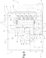
- a protective wall 61 is provided, preferably a flexible wall, e.g., a bellows wall, shown in particular in the back view of Fig.3 and in the plan view of Fig.4 .
- the wall 61 can be divided into two portions 61A and 61B, directly or indirectly constrained to the first carriage 23, so that the two wall portions 61A, 61B define a vertically developing slot for the passage of the second carriage 25 and in particular of the tools U carried by the spindles 31, and the approaching and distancing of the tools U with respect to the workpieces P carried by the pairs of headstocks 13 and tailstocks 15.
- the two wall portions 61A, 61B can for example be in the form of bellows.
- flexible walls can be used which wind and unwind on rollers with a vertical axis, or still walls formed by a plurality of sectors sliding with respect to one another so as to telescopically lengthen and shorten.
- the flexible wall 61 separates the working area of the tools U with respect to the area in which the first carriage 23 moves. Thereby, the fall of machining chips on the guides 21 and partly on the guides 27 is avoided or reduced. The chips remain confined in the front area of the flexible wall 61 and are collected by the conveyor 51.
- the flexible wall 61 can divide a booth 91, in which the lathe 1 is contained, into two volumes 91.1, 91.2.
- the first rear volume 91.1 which contains the main body 9.1 of the base 9, the guide system 20 (or part thereof), the first carriage 23, part of the second carriage 25 and part of the guide system 26.
- the second front volume 91.2 contains the work area, in which the headstocks 13 and the tailstocks 15 are located, as well as the slide 43 and the spindles 31.
- a suction system for example an extractor hood 93, in fluid connection with the second volume 91.2 to maintain the latter in a slight vacuum with respect to the outside of the booth and with respect to the first volume (91.1). Thereby, it is not necessary to keep the back volume 91.1 under vacuum. This allows to drastically reduce the energy consumption of the suction system.
- 91.3 indicates a movable openable wall, which allows the operator O access to the volume 91.2, where the workpieces P must be loaded and worked pieces unloaded.
- the numerically controlled multi-spindle lathe 1 can comprise a tool magazine 71, schematically shown only in Fig.4 and omitted in Figs. 1 to 3 for the sake of simplicity.
- the tool-holder magazine 71 can comprise one or more sets of tools U1, U2, U3, U4, which can be alternatively fitted on the spindles 31.
- multiple sets of identical tools are provided, each set comprising a plurality of superimposed tools, in a number equal to the number of spindles 31 and placed at a distance equal to the distance of the axes A in the direction of the translation axis Z.
- the tool-holder magazine 71 comprises four sets of tools U1, U2, U3, U4, each of which comprises four tools, one for each of the four spindles 31. Only one tool from each series is visible in Fig.4 .
- the tool-holder magazine 71 is a magazine rotatable around a vertical axis, as shown in Fig.4 .
- the possibility of rotation around the rotary axis C allows a high flexibility in the configuration and arrangement of the tool-holder magazine 71.
- the possibility of orienting the spindles 31 around the C axis allows easily reaching the tools U1-U4 carried by the tool-holder magazine 71.
- the symmetrical configuration of the slide 43 and the support 41 also allows the magazine 71 to be arranged indifferently on one side or the other of the lathe 1, for example depending on the space available.
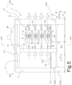
- FIG. 5 to 8 A second embodiment of a numerically controlled multi-spindle lathe 1 is illustrated in Figures 5 to 8 .
- the lathe 1 of Figures 5 to 8 has a structure largely identical to that of the lathe 1 of Figures 1 to 4 . Equal parts in the two embodiments are indicated with the same reference numbers and will not be described again.
- the first carriage 23 and the second carriage 25 are superimposed on each other and positioned above the main body 9.1 of the base 9.
- the guide system 20 is interposed between the lower part of the first carriage 23 and the upper face 9.3 of the base 9. This configuration is particularly advantageous.
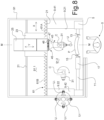
- the structure of the carriages and the base can be different, as for example illustrated in the embodiment shown in Fig.9 .
- This figure shows a section of a numerically controlled multi-spindle lathe 1 according to the present disclosure, in a section according to a vertical plane, orthogonal to the first translation axis X.
- Equal numbers indicate parts equal to or corresponding to those already described with reference to Figures 1 to 8 . These parts will not be described again, except to the extent necessary to understand the differences between the embodiment of Fig. 9 and the embodiments of Figures 1 to 8 .
- the spindles 31 and the tools U are made as in Figures 5 to 8 , but in other embodiments, the spindles 31 and the tools U of the lathe according to Fig.9 can be configured as in Figures 1 to 4 .
- the multi-spindle lathe 1 of Fig. 9 differs from the multi-spindle lathes 1 of Figures 1 to 8 mainly because the guide system 20 is not arranged on the upper face 9.3 of the main body 9.1 of the base 9, but on a side face 9.4, opposite the area in which the headstocks 13 and tailstocks 15 are arranged.
- the first carriage 23 has a lower portion projecting below the height h1 where the upper face 9.3 of the main body 9.1 of the base 1 is located.
- the shoes 24 of the guide system 20 are carried on such a lower portion, the shoes slidingly engaged on the guides 21.
- the latter are integral with the side surface or face 9.4, and are spaced apart from each other in the vertical direction parallel to the axis Z.
- the second carriage 25 is placed at the height h3, above the first carriage 23, and more precisely above the shoes 29 of the second guide system 26.
Landscapes
- Engineering & Computer Science (AREA)
- Mechanical Engineering (AREA)
- Turning (AREA)
Applications Claiming Priority (1)
| Application Number | Priority Date | Filing Date | Title |
|---|---|---|---|
| IT102023000025032A IT202300025032A1 (it) | 2023-11-24 | 2023-11-24 | Un tornio multi-mandrino a controllo numerico con mandrini multipli orientabili |
Publications (1)
| Publication Number | Publication Date |
|---|---|
| EP4559620A1 true EP4559620A1 (fr) | 2025-05-28 |
Family
ID=89845031
Family Applications (1)
| Application Number | Title | Priority Date | Filing Date |
|---|---|---|---|
| EP24213695.0A Pending EP4559620A1 (fr) | 2023-11-24 | 2024-11-18 | Tour multibroches à commande numérique avec plusieurs broches orientables |
Country Status (2)
| Country | Link |
|---|---|
| EP (1) | EP4559620A1 (fr) |
| IT (1) | IT202300025032A1 (fr) |
Citations (4)
| Publication number | Priority date | Publication date | Assignee | Title |
|---|---|---|---|---|
| EP2161098A1 (fr) | 2008-09-09 | 2010-03-10 | Wyssbrod Technologie AG | Fraiseuse |
| EP3778118A1 (fr) * | 2017-05-18 | 2021-02-17 | Fill Gesellschaft m.b.H. | Machine-outil pourvue de deux broches de travail |
| EP3858542A1 (fr) | 2020-01-30 | 2021-08-04 | Paolino Bacci S.R.L. | Tour multi-broches à contrôle numérique |
| EP4043146A1 (fr) | 2021-02-15 | 2022-08-17 | Paolino Bacci S.R.L. | Tour multibroche à commande numérique dotée d'axes de tour posés sur un plan horizontal |
-
2023
- 2023-11-24 IT IT102023000025032A patent/IT202300025032A1/it unknown
-
2024
- 2024-11-18 EP EP24213695.0A patent/EP4559620A1/fr active Pending
Patent Citations (4)
| Publication number | Priority date | Publication date | Assignee | Title |
|---|---|---|---|---|
| EP2161098A1 (fr) | 2008-09-09 | 2010-03-10 | Wyssbrod Technologie AG | Fraiseuse |
| EP3778118A1 (fr) * | 2017-05-18 | 2021-02-17 | Fill Gesellschaft m.b.H. | Machine-outil pourvue de deux broches de travail |
| EP3858542A1 (fr) | 2020-01-30 | 2021-08-04 | Paolino Bacci S.R.L. | Tour multi-broches à contrôle numérique |
| EP4043146A1 (fr) | 2021-02-15 | 2022-08-17 | Paolino Bacci S.R.L. | Tour multibroche à commande numérique dotée d'axes de tour posés sur un plan horizontal |
Also Published As
| Publication number | Publication date |
|---|---|
| IT202300025032A1 (it) | 2025-05-24 |
Similar Documents
| Publication | Publication Date | Title |
|---|---|---|
| US6428453B1 (en) | Machine tool | |
| US6099217A (en) | Device for spatially moving a body with three to six degrees of freedom in a controlled manner | |
| US10486243B2 (en) | Machining centers for metal profiles | |
| US9498833B2 (en) | Machine tool for the production of profiles | |
| EP3858542B1 (fr) | Tour multi-broches à contrôle numérique | |
| CN111002047A (zh) | 一种数控动梁式五轴龙门加工中心机床 | |
| HUP0303205A2 (hu) | Kinematikai szerkezet végső elem támasztására és programozható mozgatására | |
| CN110625443B (zh) | 一种五轴联动数控机床 | |
| CN110636920B (zh) | 具有两个工作主轴的工具机 | |
| EP4043146A1 (fr) | Tour multibroche à commande numérique dotée d'axes de tour posés sur un plan horizontal | |
| CN115229503A (zh) | 一台用于车铣复合加工多轴铣削加工的智能数控机床设备 | |
| EP2117790B1 (fr) | Centre d'usinage | |
| CN117283345A (zh) | 一种卧式加工机床 | |
| EP3851244B1 (fr) | Tour à commande numérique doté d'une structure de portique | |
| EP4559620A1 (fr) | Tour multibroches à commande numérique avec plusieurs broches orientables | |
| CN1328006C (zh) | 双龙门卧式混联原理车铣复合数控机床 | |
| JP7036843B2 (ja) | 工作機械 | |
| US20230039453A1 (en) | A numerically controlled turning center with double turning axis | |
| EP4461460A1 (fr) | Tour multibroche a controle numerique | |
| CN218503864U (zh) | 一种独立六轴数控加工设备 | |
| CN215357255U (zh) | 一种多轴龙门装置 | |
| CN210996699U (zh) | 一种六轴加工中心 | |
| CN211868089U (zh) | 一种五轴雕刻机 | |
| JPS6165710A (ja) | 多軸ヘツド式加工機械の主軸間隔設定装置 | |
| CN110666223A (zh) | 一种六轴加工中心 |
Legal Events
| Date | Code | Title | Description |
|---|---|---|---|
| PUAI | Public reference made under article 153(3) epc to a published international application that has entered the european phase |
Free format text: ORIGINAL CODE: 0009012 |
|
| STAA | Information on the status of an ep patent application or granted ep patent |
Free format text: STATUS: THE APPLICATION HAS BEEN PUBLISHED |
|
| AK | Designated contracting states |
Kind code of ref document: A1 Designated state(s): AL AT BE BG CH CY CZ DE DK EE ES FI FR GB GR HR HU IE IS IT LI LT LU LV MC ME MK MT NL NO PL PT RO RS SE SI SK SM TR |
|
| STAA | Information on the status of an ep patent application or granted ep patent |
Free format text: STATUS: REQUEST FOR EXAMINATION WAS MADE |
|
| 17P | Request for examination filed |
Effective date: 20250923 |
|
| GRAP | Despatch of communication of intention to grant a patent |
Free format text: ORIGINAL CODE: EPIDOSNIGR1 |
|
| STAA | Information on the status of an ep patent application or granted ep patent |
Free format text: STATUS: GRANT OF PATENT IS INTENDED |
|
| RIC1 | Information provided on ipc code assigned before grant |
Ipc: B23Q 39/04 20060101AFI20260113BHEP Ipc: B23Q 39/00 20060101ALN20260113BHEP |
|
| INTG | Intention to grant announced |
Effective date: 20260122 |