EP4559828A1 - Procédé d'application d'une étiquette sur des conteneurs - Google Patents
Procédé d'application d'une étiquette sur des conteneurs Download PDFInfo
- Publication number
- EP4559828A1 EP4559828A1 EP24212285.1A EP24212285A EP4559828A1 EP 4559828 A1 EP4559828 A1 EP 4559828A1 EP 24212285 A EP24212285 A EP 24212285A EP 4559828 A1 EP4559828 A1 EP 4559828A1
- Authority
- EP
- European Patent Office
- Prior art keywords
- label
- containers
- measured value
- filling
- inspection
- Prior art date
- Legal status (The legal status is an assumption and is not a legal conclusion. Google has not performed a legal analysis and makes no representation as to the accuracy of the status listed.)
- Pending
Links
Images

Classifications
-
- B—PERFORMING OPERATIONS; TRANSPORTING
- B65—CONVEYING; PACKING; STORING; HANDLING THIN OR FILAMENTARY MATERIAL
- B65C—LABELLING OR TAGGING MACHINES, APPARATUS, OR PROCESSES
- B65C9/00—Details of labelling machines or apparatus
- B65C9/40—Controls; Safety devices
-
- B—PERFORMING OPERATIONS; TRANSPORTING
- B67—OPENING, CLOSING OR CLEANING BOTTLES, JARS OR SIMILAR CONTAINERS; LIQUID HANDLING
- B67C—CLEANING, FILLING WITH LIQUIDS OR SEMILIQUIDS, OR EMPTYING, OF BOTTLES, JARS, CANS, CASKS, BARRELS, OR SIMILAR CONTAINERS, NOT OTHERWISE PROVIDED FOR; FUNNELS
- B67C3/00—Bottling liquids or semiliquids; Filling jars or cans with liquids or semiliquids using bottling or like apparatus; Filling casks or barrels with liquids or semiliquids
- B67C3/007—Applications of control, warning or safety devices in filling machinery
-
- B—PERFORMING OPERATIONS; TRANSPORTING
- B67—OPENING, CLOSING OR CLEANING BOTTLES, JARS OR SIMILAR CONTAINERS; LIQUID HANDLING
- B67C—CLEANING, FILLING WITH LIQUIDS OR SEMILIQUIDS, OR EMPTYING, OF BOTTLES, JARS, CANS, CASKS, BARRELS, OR SIMILAR CONTAINERS, NOT OTHERWISE PROVIDED FOR; FUNNELS
- B67C3/00—Bottling liquids or semiliquids; Filling jars or cans with liquids or semiliquids using bottling or like apparatus; Filling casks or barrels with liquids or semiliquids
- B67C3/02—Bottling liquids or semiliquids; Filling jars or cans with liquids or semiliquids using bottling or like apparatus
-
- B—PERFORMING OPERATIONS; TRANSPORTING
- B65—CONVEYING; PACKING; STORING; HANDLING THIN OR FILAMENTARY MATERIAL
- B65C—LABELLING OR TAGGING MACHINES, APPARATUS, OR PROCESSES
- B65C9/00—Details of labelling machines or apparatus
- B65C9/40—Controls; Safety devices
- B65C2009/402—Controls; Safety devices for detecting properties or defects of labels
- B65C2009/407—Controls; Safety devices for detecting properties or defects of labels after labelling
Definitions
- the invention relates to a method for treating containers, in particular PET bottles. Furthermore, the invention relates to a system for treating containers, in particular PET bottles.
- a container handling facility with various workstations, it is common practice to check various characteristics of the container. For example, a label affixed to the container is also checked using inspection equipment.
- a labeling machine with a labeling unit designed to apply labels to bottles.
- a label position control device is arranged in the outlet area of the labeled bottles as an inspection device, with which the desired arrangement of the labels on the bottles is monitored. If the label position changes outside a predefined tolerance limit, the label position control device transmits corresponding signals to control a correction device, which acts on the labeling units so that a correct label position can be achieved. Bottles with an incorrectly aligned label are sorted out in an ejection device.
- the invention is therefore based on the object of providing a method for treating containers, in particular PET (polyethylene terephthalate) bottles, that eliminates the above-mentioned problems and disadvantages of the prior art. Furthermore, it is the object of the present invention to provide a corresponding system for treating containers, in particular PET bottles.
- the solution according to the invention consists in particular in specifying a method for treating containers, in particular PET bottles.
- the method comprises a step for applying a label, in particular a wrap-around label, to the container. This step is carried out in or by means of a labeling machine.
- the method further comprises a step for the first inspection of the applied label. The first inspection takes place by means of a first inspection device. During the first inspection of the label, at least one first measured value relating to the label position is recorded. Independently of this, further measured values can also be recorded during the first inspection.
- the method further comprises a step for filling the containers.
- the containers are labeled, i.e., already provided with a label.
- the step of filling the containers takes place in a filling machine.
- the first inspection takes place before the containers are filled.
- the method comprises a step for a second inspection of the label after filling the containers in the filling machine.
- the second inspection step is carried out using a second inspection device.
- the second inspection device is a different inspection device than the first.
- a second measured value relating to the label position is recorded. Independently of this, additional measured values can be recorded during the second inspection.
- Treating the containers includes at least labeling or applying labels to containers, first inspecting the applied labels, filling the labeled containers and second inspecting the labels.
- Containers are generally formed as a single piece or from several parts firmly connected to one another.
- each container has a hollow space inside.
- the container is designed to separate the resulting hollow space from the surroundings.
- the container can, for example, be a container for storing, in particular, liquid, preferably carbonated, contents.
- the containers are particularly preferably bottles, in particular PET bottles.
- the labeling machine is preferably a rotary type.
- the labels are preferably wrap-around labels. Wrap-around labels are designed to completely enclose the respective container in a container region that is rotationally symmetrical, for example, with respect to a vertical or container axis.
- the label ends or narrow sides of the labels are connected in an overlapping manner.
- the filling machine can be a rotating type.
- the containers are filled with a filling material, particularly one containing carbon, and then preferably sealed.
- the applicant has determined that the internal pressure acting on the containers during or after filling, the so-called filling pressure, results in a detectable change in the label position relative to the label position before filling.
- Factors influencing the change in the label position include, for example, the wall thickness and/or material distribution during container manufacturing, particularly stretch blow molding, and the stabilization pressure during labeling, as well as the internal pressure of the containers that develops after the filling and closing process.
- the invention is therefore based on the finding that subsequent label detachment can be predicted early on by detecting changes in the label position.
- the applicant has determined that when using carbonated filling materials, the maximum container expansion is only reached after approximately 72 hours. However, immediately after filling and closing the containers, the container expansion is already so high that changes in the label position become apparent.
- any change in the label position can be tracked and appropriate measures can be initiated.
- the method further comprises the following step: comparing the first measured value and the second measured value. During the comparison, a deviation, for example a Delta of the second measured value recorded during the second inspection from the first measured value of the same container recorded during the first inspection.
- the comparison can be performed directly, particularly by a two-digit link between the two measured values.
- each measured value can of course be compared individually with a target value, thus determining the deviation of the first measured value from the target value and the deviation of the second measured value from the target value.
- the target values can be the same or different.
- the method comprises a checking step. This check determines whether the deviation determined during the comparison lies within a particularly predefined or predefinable range.
- the check it can be determined whether the deviation determined during the comparison lies within a non-critical target range in which detachment of the label from the container is not to be expected, or lies outside this target range and thus detachment of the label must be expected.
- the method comprises a step for sorting out containers for which it has been determined during inspection that the deviation lies outside the target range.
- Sorting out generally means that the containers are separated from the container flow and are therefore no longer processed with the other containers.
- the first measured value and the second measured value represent an overlap, in particular a width of the Overlap of the label, especially the wrap-around label, on the container.
- the overlap is created by connecting the label ends or narrow sides in an overlapping manner.
- the width of the overlap describes the width of the overlap along the circumference of the container. If the internal pressure in the container changes, the overlap changes, especially the width of the overlap, as the container expands accordingly due to the internal pressure. Thus, the width of the overlap can be used to inversely determine the internal pressure of the container. In general, a container with a higher internal pressure has a smaller overlap width. The width of the overlap and the internal pressure are therefore negatively correlated.
- the first measured value and the second measured value to represent an extension of the label with respect to the container surface or a position or a size of the label, in particular with respect to the container surface.
- further measured values can be recorded independently by the first and second inspection devices.
- the first inspection device can also record further measured values of the label position, such as a correct, straight position of the label.
- the second inspection device can also record the fill level of the filling material or the container shape of the container. This allows multiple inspection functions to be fulfilled using the first and second inspection devices.
- the method comprises a step for controlling and/or regulating a device of a plant for treating containers, in particular the labelling machine, in particular a setting of the device or labelling machine, based on the recorded measured values, i.e. the first measured value and the second measured value, in particular based on the deviation determined during the comparison.
- the method thus includes a control or regulation process to prevent deviations outside the target range for subsequent containers.
- the measured values are used not only for quality assurance, but also for quality-improving control of the labeling machine or other equipment.
- the labeling machine is influenced in such a way that the labeling process is adjusted so that the deviation for subsequent containers remains within the target range.
- the other equipment could be, for example, a blow molding machine, particularly a stretch blow molding machine, where, for example, the wall thickness distribution is adjusted. Alternatively, it could be a filling machine where the nitrogen dosage is adjusted.
- a stabilizing pressure introduced into the containers when the label is applied is controlled and/or regulated.
- Stabilization pressure is an internal pressure applied to the containers to stabilize them during labeling.
- the stabilization pressure is controlled and/or regulated based on the recorded measured values, i.e., the first and second measured values, and in particular based on the deviation determined during the comparison.
- the stabilization pressure is essentially controlled or regulated in relation to the filling pressure present in the containers. Since the wall thickness and/or the material distribution during stretch blow molding of the containers, for example, also have an impact on the expansion of the containers caused by the filling pressure, a control process based on the actual bottle expansion generated by the filling pressure is more precise than using the filling pressure itself.
- the stabilization pressure when controlling and/or regulating the stabilization pressure, is preferably increased stepwise, in particular adjusted in the direction of the filling pressure, until the deviation is within the target range.
- This is therefore preferably a control process in which the stabilization pressure is increased stepwise.
- control and/or regulate other settings of the labeling machine For example, it would be possible to control and/or regulate the starting point of the labeling processes, such as the time of label dispensing during labeling, to an earlier or later point in time.
- the system is specifically designed to perform the process described above. Thus, all of the aspects and advantages described above can also be applied to the treatment system.
- the system comprises a labeling machine for applying labels, in particular wrap-around labels, to containers.
- the labeling machine is thus designed to apply labels to containers.
- the system comprises a first inspection device for inspecting a label applied by the labeling machine, in particular a wrap-around label, on empty containers.
- the first inspection device is designed to record a first measured value relating to the label position of the label.
- the system comprises a filling machine for filling the labeled containers with a filling material, in particular containing carbon dioxide. The filling machine is thus designed to fill the containers with the filling material.
- the system is characterized by a second inspection device.
- the second inspection device serves to inspect the label, in particular a wrap-around label, on filled and preferably sealed containers.
- the second inspection device is designed to record a second measured value relating to the label position of the label.
- the labeling machine has, for example, a labeling carousel. At least one labeling unit is arranged on the labeling carousel, for example, although multiple labeling units can also be arranged.
- the labeling machine is therefore preferably designed as a rotating labeling machine. The containers are held in the labeling carousel, and a stabilizing pressure is applied to the containers during labeling.
- the filling machine has at least one filling unit for filling, in particular for pressure filling, the carbonated, i.e., carbonated, in particular liquid, filling material.
- the filling machine can preferably have a closing unit designed to close the container, in particular the bottle, with a lid.
- the first inspection device or the second inspection device are designed as optical detection units, in particular cameras.
- the optical detection units are designed to optically detect the measured value relating to the label.
- the optical detection unit is preferably designed as an image recording device and is suitable for recording an image of the label, in particular of the overlapping area of the label.
- the camera it can also be a CCD sensor, for example.
- the optical detection units are designed to record a peripheral section of the container moving past.
- the measured value represents an overlap, in particular the width of the overlap, of the label, in particular a wrap-around label, on the container.
- the first inspection device in particular an optical detection unit
- the first inspection device is arranged directly on the labeling machine, for example on the labeling carousel of the labeling machine.
- the optical detection unit is easily able to detect the overlap of the label as the containers are guided past the optical detection unit by means of the labeling carousel.
- the optical detection unit is arranged with its optical axis or with the image capture axis orthogonal to the overlap.
- the second inspection device is arranged downstream of the filling machine.
- the second inspection device is arranged on a transport device, in particular a conveyor belt, on which the containers are transported coming out of the filling machine.
- the containers are arranged on the transport device in such a way that the overlap can be detected by the second inspection device.
- the containers are aligned to one another in such a way that the overlaps of the labels are arranged in the same positions.
- a 360° panoramic image of the overlapping areas can be taken so that the orientation of the container is independent of the optical detection device.
- the system comprises a control and/or regulating device.
- the control and/or regulating device is connected and/or connectable to at least the first inspection device and the second inspection device, in particular in a signal-transmitting manner.
- the control and/or regulating device is designed to determine a deviation of the second measured value from the first measured value for the same container.
- the control and/or control device is preferably designed to check whether the determined deviation lies within a particularly predefined target range.
- control and/or regulating device can be designed, in particular, to compare an image captured by the second inspection device with an image of the same container captured by the first inspection device. Alternatively, it would also be possible to compare each of the captured images with a reference image.
- the system has a discharge device which is designed to discharge containers for which the deviation lies outside the target range.
- the ejection device is preferably connected to, or connectable to, a control and/or regulating device, for example, the one already described.
- control and/or regulating device is designed to control and/or regulate devices of the system, in particular the labeling machine, in particular a setting of the labeling machine, based on the recorded measured values, i.e. the first measured value and the second measured value, in particular based on the determined deviation.
- the other equipment in the system may, for example, be a blow molding machine, particularly a stretch blow molding machine, where, for example, the wall thickness distribution is adjusted. Alternatively, it may be a filling machine where the nitrogen dosage is adjusted.
- control and/or regulating device is designed to control and/or regulate a stabilization pressure of the labeling machine introduced during the application of the label to the container.
- the control and/or regulation of the stabilization pressure is carried out based on the recorded measured values, and in particular based on the deviation determined during the comparison.
- the system comprises a blow molding machine for producing the containers, wherein the blow molding machine, the labeling machine, and the filling machine form a single unit and thus a combination machine.
- the system is designed as a combination machine comprising the blow molding machine, the labeling machine, and the filling machine.
- the containers are manufactured from preforms in the blow molding machine.
- Blow molding is preferably stretch blow molding.
- stretch blow molding the preform is heated, held in a cavity, and enclosed within it.
- a mandrel is then pressed into the preform from above, and compressed air is forced into the preform, inflating it and pressing it against the contour of the blow molding tool or cavity.
- the wall thickness and/or material distribution can vary during stretch blow molding, particularly depending on the quality of the preform.
- the labeling quality depends on a wide variety of factors.
- the wall thickness and material distribution during stretch blow molding, the stabilization pressure during labeling, and the carbonated filling material added during filling have already been mentioned. This determines the container diameter to which the labels are applied. must be applied is variable and changes within the block machine, so that applied labels can later detach from the container.
- FIG. 1 A simplified flow diagram of the container treatment process is shown.
- a first step 110 labels are applied to containers. This involves labeling the containers. Step 110 is carried out in or by means of a labeling machine.
- a first inspection of the label applied in step 110 takes place.
- the step 120 is carried out by means of a first inspection device, wherein during the first inspection a
- the first measured value can be, for example, the value in Fig. 3 represented overlap, in particular a width of the overlap, of the label on the container.
- Step 130 the containers labeled in step 110 and inspected in step 120 are filled.
- Step 130 is performed using a filling machine.
- the containers are also sealed in step 130.
- the containers are then pressurized, the so-called filling pressure.
- a second inspection of the label applied in step 110 takes place, specifically after the filling of the containers in step 130.
- Step 140 is carried out using a second inspection device.
- a measured value relating to the label position namely a second measured value, is also recorded.
- the second measured value can also be the Fig. 3 represented overlap, in particular a width of the overlap, of the label on the container.
- step 150 the first measured value acquired in step 120 and the second measured value acquired in step 140 are compared. In comparison step 150, a deviation of the second measured value from the first measured value for one and the same container is determined. Step 150 is carried out, in particular, by means of a control and/or regulating device.
- the control and/or regulating device is also configured to execute the subsequent step 160.
- step 160 a check is performed to determine whether the deviation determined during the comparison in step 150 lies within a target range. If the deviation lies within the target range, the containers are transported further in the container stream in step 190. If the deviation lies outside the predefined target range, the checked container is sorted out in step 170. The container is thus removed from the container stream.
- step 180 the labeling machine used in step 110 is also controlled and/or regulated.
- a setting of the labeling machine is controlled and/or regulated based on the measured values acquired in step 120 and step 140.
- the control and/or regulation in step 180 is based on the deviation determined in step 150.
- the setting of the labeling machine is preferably a stabilization pressure of the labeling machine, which is applied to the containers when the label is applied in step 110.
- the filling pressure applied in step 130 is higher than the stabilization pressure of the labeling machine. This causes the container to expand after filling, which can trigger a change in the label fit.
- Fig. 2 shows a system 200 by means of which the Fig. 1
- the method for treating containers outlined above is possible.
- the system 200 may, in particular, be a combination machine in which the machines shown are designed as a single structural unit.
- the system 200 then has a blow molding machine 270, by means of which the Fig. 3
- the containers 10 shown are produced from preforms.
- the containers 10 are fed to a labeling machine 210 of the system 200.
- the labeling machine 210 has a labeling carousel 211 and a labeling unit 212.
- the Fig. 3 The labels 11 shown, in particular wrap-around labels, are applied to the containers 10.
- the labels 11 are applied in particular by means of the labeling unit 212.
- a first inspection device 220 is arranged on the labeling carousel 211.
- the first inspection device 220 is arranged in the container flow behind the labeling unit 212 and is designed to detect a first measured value relating to the label position of the label 11.
- the first measured value is preferably one in Fig. 3
- the label ends or narrow sides of the labels 11 are connected in an overlapping manner. If the internal pressure in the container 10 changes, the overlap 13, in particular the width of the overlap 13, can change, since the container 10 expands accordingly due to the internal pressure.
- the containers 10 are transported to a filling machine 230 of the system 200.
- the containers 10 are filled with a filling material 12, in particular containing carbon dioxide (recognizable in Fig. 3 ).
- the containers 10 are transported to a second inspection device 240.
- the second inspection device 240 is also designed to inspect the label 11.
- the second inspection device 240 is designed to record a second measured value relating to the label position of the label 11. This second measured value is also the Fig. 3 overlap shown 13.
- the first inspection device 220 and the second inspection device 240 are preferably designed as optical detection units, in particular as cameras, so that the measured values relating to the label 11 are optically detected.
- the second inspection device 240 inspects the containers 10 or the labels 11 after filling and preferably closing the containers 10.
- the internal pressure acting on the containers 10 after filling i.e., the filling pressure, causes a detectable change in the label position relative to the label position before filling the containers 10. A subsequent detachment of the label 11 can be predicted based on these changes in the label position.
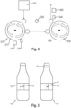
- the container 10 On the left-hand side, the container 10 is shown as it is detected, for example, by the first inspection device 220.
- the label 11, designed as a wrap-around label, has a relatively wide overlap 13.
- the container 10 On the right-hand side, the container 10 is shown as it is detected, for example, by the second inspection device 240. Firstly, it can be seen that the container 10 is now filled with the filling material 12. It can also be seen that the overlap 13 of the label 11 has changed, in particular has decreased. There is therefore a deviation in the overlap 13 on the left and right sides.
- the reason for the deviation is a pressure change within the container 10. After filling, the container 10 is subjected to higher pressure, particularly internal pressure, which leads to an expansion of the surface of the container 10. The overlap 13 decreases accordingly. Containers 10 exhibiting a high deviation tend to have the label 11 detach during or after storage. Accordingly, these containers should preferably be removed from the container flow.
- the system 200 shown has a discharge device 260.
- the system 200 further comprises a control and/or regulating device 250.
- the control and/or regulating device 250 is designed, in particular, to determine the deviation of the second measured value from the first measured value and to check whether the determined deviation lies within a target range.
- the discharge device 260 can then also be controlled via the target range, with containers 10 being discharged if the deviation lies outside the target range.
- a correction of the process sequence can be carried out by means of the control and/or regulating device.
- the control and/or regulating device is designed to control and/or regulate a setting of the labeling machine 210.
- the setting can be a stabilization pressure of the labeling machine 210. If for example, if the stabilization pressure on container 10 increases, the container 10 expands during labeling, so that the overlap 13 is correspondingly smaller. Thus, the deviation from the width of the overlap 13, which is detected by the second inspection device 240 after filling, i.e., when the container 10 is pressurized, is also smaller. Accordingly, the system 200 can be controlled so that more containers 10 are within the target range.
Landscapes
- Labeling Devices (AREA)
Applications Claiming Priority (1)
| Application Number | Priority Date | Filing Date | Title |
|---|---|---|---|
| DE102023132709.7A DE102023132709A1 (de) | 2023-11-23 | 2023-11-23 | Verfahren zum Behandeln von Behältern und Anlage zum Behandeln von Behältern |
Publications (1)
| Publication Number | Publication Date |
|---|---|
| EP4559828A1 true EP4559828A1 (fr) | 2025-05-28 |
Family
ID=93520820
Family Applications (1)
| Application Number | Title | Priority Date | Filing Date |
|---|---|---|---|
| EP24212285.1A Pending EP4559828A1 (fr) | 2023-11-23 | 2024-11-12 | Procédé d'application d'une étiquette sur des conteneurs |
Country Status (2)
| Country | Link |
|---|---|
| EP (1) | EP4559828A1 (fr) |
| DE (1) | DE102023132709A1 (fr) |
Citations (6)
| Publication number | Priority date | Publication date | Assignee | Title |
|---|---|---|---|---|
| DE102004005994A1 (de) | 2004-02-06 | 2005-09-08 | Khs Maschinen- Und Anlagenbau Ag | Etikettiermaschine mit Ausrichtvorrichtung für Module |
| EP1627816B1 (fr) | 2004-08-21 | 2008-04-16 | Khs Ag | Procédé d'étiquetage de récipients et étiqueteuse pour la mise en oeuvre du procédé |
| WO2015128245A1 (fr) * | 2014-02-25 | 2015-09-03 | Khs Gmbh | Dispositif d'inspection |
| DE102014112484A1 (de) * | 2014-08-29 | 2016-03-03 | Krones Aktiengesellschaft | Vorrichtung und Verfahren zum Ausstatten von Behältnissen und Stationsstilllegung |
| EP3153419A1 (fr) * | 2015-10-05 | 2017-04-12 | Sidel Participations | Procédé et appareil de manipulation de récipients |
| EP2927139B1 (fr) * | 2014-03-31 | 2017-10-11 | Sidel S.p.a. Con Socio Unico | Machine et procédé d'étiquetage d'articles |
Family Cites Families (2)
| Publication number | Priority date | Publication date | Assignee | Title |
|---|---|---|---|---|
| DE202009012064U1 (de) * | 2009-09-07 | 2011-02-03 | Heuft Systemtechnik Gmbh | Vorrichtung zum Fördern von Objekten, Etikettiervorrichtung, Inspektionsvorrichtung und Rotationsfüller mit einer derartigen Fördervorrichtung |
| DE102009040977B4 (de) * | 2009-09-11 | 2022-12-15 | Krones Aktiengesellschaft | Behältnisbehandlungsanlage und ein Behältnisbehandlungsverfahren zum Behandeln von mit einem Produkt befüllbaren Behältnissen |
-
2023
- 2023-11-23 DE DE102023132709.7A patent/DE102023132709A1/de active Pending
-
2024
- 2024-11-12 EP EP24212285.1A patent/EP4559828A1/fr active Pending
Patent Citations (6)
| Publication number | Priority date | Publication date | Assignee | Title |
|---|---|---|---|---|
| DE102004005994A1 (de) | 2004-02-06 | 2005-09-08 | Khs Maschinen- Und Anlagenbau Ag | Etikettiermaschine mit Ausrichtvorrichtung für Module |
| EP1627816B1 (fr) | 2004-08-21 | 2008-04-16 | Khs Ag | Procédé d'étiquetage de récipients et étiqueteuse pour la mise en oeuvre du procédé |
| WO2015128245A1 (fr) * | 2014-02-25 | 2015-09-03 | Khs Gmbh | Dispositif d'inspection |
| EP2927139B1 (fr) * | 2014-03-31 | 2017-10-11 | Sidel S.p.a. Con Socio Unico | Machine et procédé d'étiquetage d'articles |
| DE102014112484A1 (de) * | 2014-08-29 | 2016-03-03 | Krones Aktiengesellschaft | Vorrichtung und Verfahren zum Ausstatten von Behältnissen und Stationsstilllegung |
| EP3153419A1 (fr) * | 2015-10-05 | 2017-04-12 | Sidel Participations | Procédé et appareil de manipulation de récipients |
Also Published As
| Publication number | Publication date |
|---|---|
| DE102023132709A1 (de) | 2025-05-28 |
Similar Documents
| Publication | Publication Date | Title |
|---|---|---|
| EP2759829A1 (fr) | Installation de fabrication pour la fabrication de récipients à partir d'ébauches de récipients et procédé de fabrication | |
| EP3564006B1 (fr) | Dispositif de transport et de vérification de préformes | |
| EP2876053B1 (fr) | Dispositif de déviation d'un tube de film plastique et un procédé de commande d'un dispositif de déviation | |
| EP1627816A1 (fr) | Procédé d'étiquetage de récipients et étiqueteuse pour la mise en oeuvre du procédé | |
| EP4201637B1 (fr) | Dispositif et procédé de fabrication de récipients en plastique dotés de sections transversales non circulaires | |
| EP3623791A1 (fr) | Dispositif de contrôle d'un raccordement d'une bande d'inviolabilité d'une protection d'originalité d'un couvercle de fermeture avec un corps de base de couvercle | |
| EP4335622A1 (fr) | Procédé et dispositif de traitement de récipients avec identification de récipients déviés | |
| EP3808530A1 (fr) | Procédé et agencement de remplissage des pièces en matière plastique | |
| DE202017107845U1 (de) | Behälterorientierung über eine Schnecke | |
| DE102014119206B4 (de) | Verfahren und Messvorrichtung für die Überwachung der Dehnfähigkeit bei der Herstellung von Stretchfolie in einem Gießfolienverfahren und Folienmaschine | |
| EP3046864B1 (fr) | Procédé et dispositif pour le remplissage de récipients en matériau synthétique de forme instable par un matériau de remplissage liquide | |
| DE102019005487B3 (de) | Verfahren zur Wandstärkenmessung eines Hohlglasartikels | |
| EP4559828A1 (fr) | Procédé d'application d'une étiquette sur des conteneurs | |
| EP4007725A1 (fr) | Dispositif et procédé pour aligner des récipients | |
| EP3802401A1 (fr) | Dispositif et procédé de traitement de récipients remplis d'un produit de remplissage liquide moussant | |
| EP4276450A1 (fr) | Dispositif et procédé d'inspection de récipients avec détection de position | |
| DE202018104327U1 (de) | System zum Erfassen von Defekten in einem zu füllenden Behälter und dazugehörige kombinierte Anlage zur Behandlung von Behältern | |
| EP4265391A1 (fr) | Dispositif et procédé de fabrication de récipients en plastique dotés de sections transversales non circulaires | |
| EP3678868B1 (fr) | Dispositif d'impression directe pour l'application d'une image imprimée périphérique | |
| WO2018054790A1 (fr) | Procédé et dispositif de fabrication de récipients | |
| DE102019117825A1 (de) | Verfahren zur Kontrolle und Steuerung des Drehmoments beim automatisierten Aufdrehen von Aufsätzen auf Flaschen | |
| DE102023126405A1 (de) | Verfahren und Vorrichtung zum Herstellen von Behältern | |
| DE102019201424A1 (de) | Verfahren zum Etikettieren von Verpackungen | |
| EP4585399A1 (fr) | Dispositif et procédé de fabrication de récipients en plastique avec inspection de préformes en plastique | |
| DE102021133791A1 (de) | Vorrichtung und Verfahren zum Herstellen von Kunststoffbehältnissen mit nicht kreisförmigen Querschnitten |
Legal Events
| Date | Code | Title | Description |
|---|---|---|---|
| PUAI | Public reference made under article 153(3) epc to a published international application that has entered the european phase |
Free format text: ORIGINAL CODE: 0009012 |
|
| STAA | Information on the status of an ep patent application or granted ep patent |
Free format text: STATUS: THE APPLICATION HAS BEEN PUBLISHED |
|
| AK | Designated contracting states |
Kind code of ref document: A1 Designated state(s): AL AT BE BG CH CY CZ DE DK EE ES FI FR GB GR HR HU IE IS IT LI LT LU LV MC ME MK MT NL NO PL PT RO RS SE SI SK SM TR |
|
| STAA | Information on the status of an ep patent application or granted ep patent |
Free format text: STATUS: REQUEST FOR EXAMINATION WAS MADE |
|
| 17P | Request for examination filed |
Effective date: 20250620 |
|
| P01 | Opt-out of the competence of the unified patent court (upc) registered |
Free format text: CASE NUMBER: UPC_APP_0014560_4559828/2025 Effective date: 20251125 |