EP4559848A2 - Transport d'articles de formats differents - Google Patents
Transport d'articles de formats differents Download PDFInfo
- Publication number
- EP4559848A2 EP4559848A2 EP25170037.3A EP25170037A EP4559848A2 EP 4559848 A2 EP4559848 A2 EP 4559848A2 EP 25170037 A EP25170037 A EP 25170037A EP 4559848 A2 EP4559848 A2 EP 4559848A2
- Authority
- EP
- European Patent Office
- Prior art keywords
- movement devices
- guide track
- group
- movement
- objects
- Prior art date
- Legal status (The legal status is an assumption and is not a legal conclusion. Google has not performed a legal analysis and makes no representation as to the accuracy of the status listed.)
- Pending
Links
Images


Classifications
-
- B—PERFORMING OPERATIONS; TRANSPORTING
- B65—CONVEYING; PACKING; STORING; HANDLING THIN OR FILAMENTARY MATERIAL
- B65G—TRANSPORT OR STORAGE DEVICES, e.g. CONVEYORS FOR LOADING OR TIPPING, SHOP CONVEYOR SYSTEMS OR PNEUMATIC TUBE CONVEYORS
- B65G47/00—Article or material-handling devices associated with conveyors; Methods employing such devices
- B65G47/74—Feeding, transfer, or discharging devices of particular kinds or types
- B65G47/90—Devices for picking-up and depositing articles or materials
- B65G47/907—Devices for picking-up and depositing articles or materials with at least two picking-up heads
-
- B—PERFORMING OPERATIONS; TRANSPORTING
- B65—CONVEYING; PACKING; STORING; HANDLING THIN OR FILAMENTARY MATERIAL
- B65G—TRANSPORT OR STORAGE DEVICES, e.g. CONVEYORS FOR LOADING OR TIPPING, SHOP CONVEYOR SYSTEMS OR PNEUMATIC TUBE CONVEYORS
- B65G54/00—Non-mechanical conveyors not otherwise provided for
- B65G54/02—Non-mechanical conveyors not otherwise provided for electrostatic, electric, or magnetic
-
- B—PERFORMING OPERATIONS; TRANSPORTING
- B65—CONVEYING; PACKING; STORING; HANDLING THIN OR FILAMENTARY MATERIAL
- B65G—TRANSPORT OR STORAGE DEVICES, e.g. CONVEYORS FOR LOADING OR TIPPING, SHOP CONVEYOR SYSTEMS OR PNEUMATIC TUBE CONVEYORS
- B65G47/00—Article or material-handling devices associated with conveyors; Methods employing such devices
- B65G47/74—Feeding, transfer, or discharging devices of particular kinds or types
- B65G47/90—Devices for picking-up and depositing articles or materials
-
- B—PERFORMING OPERATIONS; TRANSPORTING
- B65—CONVEYING; PACKING; STORING; HANDLING THIN OR FILAMENTARY MATERIAL
- B65B—MACHINES, APPARATUS OR DEVICES FOR, OR METHODS OF, PACKAGING ARTICLES OR MATERIALS; UNPACKING
- B65B43/00—Forming, feeding, opening or setting-up containers or receptacles in association with packaging
- B65B43/42—Feeding or positioning bags, boxes, or cartons in the distended, opened, or set-up state; Feeding preformed rigid containers, e.g. tins, capsules, glass tubes, glasses, to the packaging position; Locating containers or receptacles at the filling position; Supporting containers or receptacles during the filling operation
- B65B43/46—Feeding or positioning bags, boxes, or cartons in the distended, opened, or set-up state; Feeding preformed rigid containers, e.g. tins, capsules, glass tubes, glasses, to the packaging position; Locating containers or receptacles at the filling position; Supporting containers or receptacles during the filling operation using grippers
-
- B—PERFORMING OPERATIONS; TRANSPORTING
- B65—CONVEYING; PACKING; STORING; HANDLING THIN OR FILAMENTARY MATERIAL
- B65B—MACHINES, APPARATUS OR DEVICES FOR, OR METHODS OF, PACKAGING ARTICLES OR MATERIALS; UNPACKING
- B65B59/00—Arrangements to enable machines to handle articles of different sizes, to produce packages of different sizes, to vary the contents of packages, to handle different types of packaging material, or to give access for cleaning or maintenance purposes
-
- B—PERFORMING OPERATIONS; TRANSPORTING
- B65—CONVEYING; PACKING; STORING; HANDLING THIN OR FILAMENTARY MATERIAL
- B65C—LABELLING OR TAGGING MACHINES, APPARATUS, OR PROCESSES
- B65C9/00—Details of labelling machines or apparatus
- B65C9/02—Devices for moving articles, e.g. containers, past labelling station
-
- B—PERFORMING OPERATIONS; TRANSPORTING
- B65—CONVEYING; PACKING; STORING; HANDLING THIN OR FILAMENTARY MATERIAL
- B65G—TRANSPORT OR STORAGE DEVICES, e.g. CONVEYORS FOR LOADING OR TIPPING, SHOP CONVEYOR SYSTEMS OR PNEUMATIC TUBE CONVEYORS
- B65G47/00—Article or material-handling devices associated with conveyors; Methods employing such devices
- B65G47/74—Feeding, transfer, or discharging devices of particular kinds or types
- B65G47/90—Devices for picking-up and depositing articles or materials
- B65G47/901—Devices for picking-up and depositing articles or materials provided with drive systems with rectilinear movements only
-
- B—PERFORMING OPERATIONS; TRANSPORTING
- B67—OPENING, CLOSING OR CLEANING BOTTLES, JARS OR SIMILAR CONTAINERS; LIQUID HANDLING
- B67C—CLEANING, FILLING WITH LIQUIDS OR SEMILIQUIDS, OR EMPTYING, OF BOTTLES, JARS, CANS, CASKS, BARRELS, OR SIMILAR CONTAINERS, NOT OTHERWISE PROVIDED FOR; FUNNELS
- B67C3/00—Bottling liquids or semiliquids; Filling jars or cans with liquids or semiliquids using bottling or like apparatus; Filling casks or barrels with liquids or semiliquids
- B67C3/02—Bottling liquids or semiliquids; Filling jars or cans with liquids or semiliquids using bottling or like apparatus
- B67C3/22—Details
- B67C3/24—Devices for supporting or handling bottles
-
- B—PERFORMING OPERATIONS; TRANSPORTING
- B65—CONVEYING; PACKING; STORING; HANDLING THIN OR FILAMENTARY MATERIAL
- B65G—TRANSPORT OR STORAGE DEVICES, e.g. CONVEYORS FOR LOADING OR TIPPING, SHOP CONVEYOR SYSTEMS OR PNEUMATIC TUBE CONVEYORS
- B65G2201/00—Indexing codes relating to handling devices, e.g. conveyors, characterised by the type of product or load being conveyed or handled
- B65G2201/02—Articles
- B65G2201/0235—Containers
- B65G2201/0241—Barrels, drums
-
- B—PERFORMING OPERATIONS; TRANSPORTING
- B65—CONVEYING; PACKING; STORING; HANDLING THIN OR FILAMENTARY MATERIAL
- B65G—TRANSPORT OR STORAGE DEVICES, e.g. CONVEYORS FOR LOADING OR TIPPING, SHOP CONVEYOR SYSTEMS OR PNEUMATIC TUBE CONVEYORS
- B65G2201/00—Indexing codes relating to handling devices, e.g. conveyors, characterised by the type of product or load being conveyed or handled
- B65G2201/02—Articles
- B65G2201/0235—Containers
- B65G2201/0244—Bottles
-
- B—PERFORMING OPERATIONS; TRANSPORTING
- B65—CONVEYING; PACKING; STORING; HANDLING THIN OR FILAMENTARY MATERIAL
- B65G—TRANSPORT OR STORAGE DEVICES, e.g. CONVEYORS FOR LOADING OR TIPPING, SHOP CONVEYOR SYSTEMS OR PNEUMATIC TUBE CONVEYORS
- B65G2201/00—Indexing codes relating to handling devices, e.g. conveyors, characterised by the type of product or load being conveyed or handled
- B65G2201/02—Articles
- B65G2201/0235—Containers
- B65G2201/025—Boxes
-
- B—PERFORMING OPERATIONS; TRANSPORTING
- B65—CONVEYING; PACKING; STORING; HANDLING THIN OR FILAMENTARY MATERIAL
- B65G—TRANSPORT OR STORAGE DEVICES, e.g. CONVEYORS FOR LOADING OR TIPPING, SHOP CONVEYOR SYSTEMS OR PNEUMATIC TUBE CONVEYORS
- B65G2201/00—Indexing codes relating to handling devices, e.g. conveyors, characterised by the type of product or load being conveyed or handled
- B65G2201/02—Articles
- B65G2201/0235—Containers
- B65G2201/0252—Cans
Definitions
- the invention relates to devices and methods for transporting objects, preferably containers.
- Container processing systems typically consist of a series of different, sequentially arranged processing stations. At these stations, the containers undergo various treatments. This can include, for example, filling, sealing, or labeling. There are a variety of options for transporting the containers between the stations. There are intermittent machines, such as those used for the production of beverage cartons. Here, the containers are usually transported by a chain. Machines for filling beverage containers typically use transfer starwheels to transport the containers through the system.
- linear motor technology e.g., in the form of long-stator linear motor systems or short-stator linear motor systems.
- a stationary long stator with electromagnets can be used to effect movement of the moving devices equipped with permanent magnets.
- the moving devices can each have a short stator formed by electromagnets, which can enter into magnetic interaction with stationary permanent magnets to move the moving device.
- the moving devices also called “shuttles" or “mover,” can each move one or more containers.
- a major advantage of linear motor technology is that the moving devices can be controlled individually or separately and independently of one another.
- the WO 2019/159116 A1 discloses a machine for treating or conveying containers, comprising a guide extending along a feed direction for feeding the containers, and a plurality of carriages for carrying the containers, which slide one behind the other on the same guide are mounted.
- the guide and each carriage together define corresponding linear motors.
- Each support carriage comprises, in particular, two gripping means, each mounted on different and successive carriages along the same guide.
- the carriages are movable toward or away from each other to regulate the mutual spacing along the feed direction for the feeding of the containers and to define a gripping area of the gripping means between them, depending on the type of container to be removed or released.
- the EP 3 109 189 A1 discloses a transfer device for transporting a sequence of packaging units along a transfer path.
- the transfer device comprises a first circulating carrier having at least one operative branch parallel to the transfer path, at least one first conveyor element advanced along the first circulating carrier, a second circulating carrier adjacent to the first circulating carrier and having at least one operative branch parallel to the transfer path, and at least one second conveyor element independently controlled from the first conveyor element and advanced along the second circulating carrier.
- the first conveyor element and the second conveyor element are configured to each hold a packaging unit therebetween and advance such a packaging unit along the transfer path.
- the invention is based on the object of further developing the previously described techniques in such a way that objects, preferably containers, of different formats can be transported in a simple manner without converting the device, preferably with the smallest possible pitch.
- One aspect of the present disclosure relates to a device for transporting objects, preferably containers, along a transport path, comprising at least one (e.g., closed or circumferential) guide track.
- the device further comprises first movement devices and second movement devices for transporting the objects.
- the first movement devices and the second movement devices are guided alternately one behind the other along the at least one guide track and can be driven individually, preferably by means of a long-stator linear drive or a short-stator linear drive.
- the device further comprises a control unit configured to operate the device in a first operating mode and in a second operating mode. In the first operating mode and in the second operating mode, the objects are each transported by pairs, each formed from one of the first moving devices and one of the second moving devices.
- the pairs are formed such that the first moving device is positioned in front of the second moving device of the respective pair in a direction of the transport path.
- the pairs are formed such that the second moving device is positioned in front of the first moving device of the respective pair in the direction of the transport path.
- the device advantageously enables a wide variety of objects, preferably containers, to be transported without mechanical format conversion on the movement devices. Furthermore, a comparatively small pitch (distance between consecutively transported objects) can be achieved, which is important for high machine performance.
- the cooperation of the movement devices for transporting the objects can be changed.
- the device can be operated in the first operating mode.
- the device can be operated in the second operating mode.
- the format change can therefore be carried out simply using control technology by changing the operating mode.
- the first movement devices and the second movement devices can be designed to transport the objects in a hanging, carrying or sliding manner over a base surface.
- the first movement devices and the second movement devices are guided along the same guideway.
- control unit is configured to operate the device for transporting objects of a first format in the first operating mode and for transporting objects of a second format, which differs from the first format, preferably in a shape and/or a size, in the second operating mode.
- first movement devices and the second movement devices differ from one another, preferably with respect to an arrangement and/or configuration of a support for the objects.
- first movement devices and the second movement devices can thus be adapted to very different formats and/or enable a very small separation during transport, even though the objects may be comparatively large.
- first movement devices and the second movement devices can be structurally identical but aligned differently with respect to the at least one guide track, wherein preferably the second movement devices are rotated by substantially 180° about a respective pitch axis of the second movement devices relative to the first movement devices.
- the first movement devices and the second movement devices each have a first, preferably V-shaped, ring-segment-shaped or planar, support section directed in the direction of the transport path, and a second, preferably V-shaped, ring-segment-shaped or planar, support section directed opposite to the direction of the transport path, for supporting the objects during transport.
- the objects are each supported between the second support section of the first movement devices and the first support section of the second movement devices.
- the objects are each supported between the first support section of the first movement devices and the second support section of the second movement devices.
- the second support portion of the first movement device and the first support portion of the second movement device of the respective pair may face each other.
- the first support portion of the first movement device and the second support portion of the second movement device of the respective pair may face each other.
- first support sections of the first movement devices and the second support sections of the first movement devices are structurally different.
- first support sections of the second movement devices are structurally designed like the second support sections of the first movement devices, and/or The second support sections of the second movement devices are designed in the same way as the first support sections of the first movement devices.
- This advantageously allows, for example, objects with very different formats, e.g., conical and cylindrical containers, to be transported equally by the device.
- the conical containers can be transported in the first operating mode.
- the cylindrical containers can, in turn, be transported in the second operating mode.
- first support sections of the first movement devices, the second support sections of the first movement devices, the first support sections of the second movement devices, and/or the second support sections of the second movement devices are of identical construction.
- structural design of the support sections in this embodiment can already be such that different formats of objects can be supported for transport using the same support sections.
- first support sections of the first movement devices are set back with respect to the direction of the transport path and/or the second support sections of the second movement devices are set back in a direction opposite to the direction of the transport path.
- second support sections of the first movement devices can protrude in a direction opposite to the direction of the transport path and/or the first support sections of the second movement devices can protrude with respect to the direction of the transport path. This advantageously allows a small pitch to be achieved when transporting large objects.
- the first movement devices and the second movement devices each have a support arm which supports the first support section and the second support section of the respective movement device, preferably at the same end of the support arm.
- the support arms of the first movement devices and the support arms of the second movement devices can be offset in opposite directions to one another.
- the offset of the support arms can thus be directed outwards in the second operating mode, e.g. for large objects.
- the offset of the support arms can be directed inwards in the first operating mode. In this way, even with large containers, a division can be achieved which is significantly smaller than that which can be achieved with a rigid assignment of movement devices.
- a further aspect of the present disclosure relates to a device for transporting objects, preferably containers, along a transport path, comprising at least one (e.g., closed or circumferential) guide track.
- the device has a plurality of movement devices for transporting the objects, wherein the plurality of movement devices are guided along the at least one guide track and can be driven individually, preferably by means of a long-stator linear drive or a short-stator linear drive.
- the device has a control unit configured to control the plurality of movement devices such that a group of at least three of the plurality of movement devices jointly transports an object positioned between them, preferably clamped, along the transport path to a transfer area of the device for transferring the object.
- the device can achieve a very high degree of flexibility in the transportable formats without having to retool the movement devices. Due to the large number of contact points with the object provided by the at least three movement devices, almost any contour can be transported. A format change can, in turn, be easily achieved purely through control technology by changing the arrangement of the movement devices relative to one another. Time-consuming and costly mechanical retooling of the movement devices during format changes can be dispensed with.
- control unit is configured such that the groups are each formed from exactly three of the plurality of movement devices, wherein the object is preferably supported or carried in a three-point bearing by the exactly three movement devices of the respective group, preferably on a peripheral surface or lateral surface of the object.
- the at least one guide track comprises a first guide track and a second guide track, which extend substantially parallel and are arranged one above the other.
- the control unit is configured to form a first group of the groups such that one of the three movement devices of the first group is guided along the first guide track and the other two of the three movement devices of the first group are guided along the second guide track.
- the control unit is further configured to form a second group of the groups, preferably directly following the first group, such that that two of the three moving devices of the second group are guided along the first guide track, and the other of the three moving devices of the second group is guided along the second guide track.
- this allows a minimum possible separation to be reduced particularly effectively, since consecutive objects can be transported very close to one another.
- the first group and the second group can overlap each other in a plan view of the device or the groups from above during transport.
- control unit is configured such that the groups are each formed from exactly four of the plurality of movement devices, wherein the object is preferably supported or carried in a four-point mounting by the exactly four movement devices of the respective group, preferably on a peripheral surface or lateral surface of the object.
- the four-point mounting can enable particularly great flexibility with regard to possible contours of transportable objects.
- the at least one guide track can comprise a first guide track and a second guide track, which extend substantially parallel and are arranged one above the other.
- the control unit can preferably be configured to form the groups such that, in each group, two of the four movement devices are guided along the first guide track and the other two of the four movement devices are guided along the second guide track.
- a further aspect of the present disclosure relates to a treatment system for treating containers, comprising a device as disclosed herein.
- the device can enable the achievable pitch (distance) of the treatment stations of the treatment system to be minimized, since this pitch can be adapted to or correspond to a minimum achievable pitch when transporting the objects through the device.
- the device can enable the movement devices to move very close together to achieve a small pitch, for example, in order to keep the distance between two consecutive filling valves as small as possible.
- the treatment plant can be designed for producing, cleaning, coating, testing, filling, closing, labeling, printing and/or packaging containers for liquid media, preferably beverages or liquid foodstuffs.
- the containers can be designed as bottles, cans, canisters, cartons, flasks, etc.
- the treatment system can preferably have a plurality of treatment stations (e.g., filling stations, closing stations, and/or labeling stations) for the containers transported by the device, wherein the plurality of treatment stations are arranged along the at least one guide track.
- a plurality of, e.g., five, filling valves are positioned one behind the other on the guide track, the device can always move several or five containers simultaneously under these filling valves and fill them there. After the filling process is complete, the device moves the several or five filled containers further, and several or five new, empty containers are moved by the device under the filling valves. Since the device enables a very small pitch or pitch distance, the changeover can require comparatively little time, thus increasing performance.
- control unit can refer to electronics (e.g., implemented as a driver circuit or with microprocessor(s) and data memory) that, depending on its design, can perform control and/or regulation tasks and/or processing tasks.
- control can also appropriately include or mean “regulation” or “control with feedback” and/or “processing.”
- a further aspect of the present disclosure relates to a method for transporting objects, preferably containers, with different formats by means of a device, preferably as disclosed herein, which has at least one (e.g., closed or circulating) guideway as well as first movement devices and second movement devices for transporting the objects, wherein the first movement devices and the second movement devices are guided alternately one behind the other along the at least one guideway and are individually drivable, preferably by means of a long-stator linear drive or a short-stator linear drive.
- a device preferably as disclosed herein, which has at least one (e.g., closed or circulating) guideway as well as first movement devices and second movement devices for transporting the objects, wherein the first movement devices and the second movement devices are guided alternately one behind the other along the at least one guideway and are individually drivable, preferably by means of a long-stator linear drive or a short-stator linear drive.
- the method comprises transporting an object with a first format by means of a pair of one of the first movement devices and one of the second movement devices (e.g., in the first operating mode and/or controlled by a control unit of the device), wherein the first movement device is positioned in one direction of the transport path in front of the second movement device of the pair.
- the method comprises transporting an object with a second format that differs from the first Format, preferably in a size and/or in a shape, by means of a pair of one of the first movement devices and one of the second movement devices (e.g. in the second operating mode and/or controlled by a control unit of the device), wherein the second movement device is positioned in front of the first movement device of the pair in the direction of the transport path.
- the method can achieve the same advantages as have already been described with regard to the corresponding device.
- a further aspect of the present disclosure relates to a method for transporting objects, preferably containers, with different formats by means of a device, preferably as described herein, which has at least one (e.g. closed or circulating) guide track and a plurality of movement devices for transporting the objects along a transport path, wherein the plurality of movement devices are guided along the at least one guide track and can be driven individually, preferably by means of a long stator linear drive or a short stator linear drive.
- the method comprises transporting objects of different formats, each by means of a group of at least three movement devices (e.g., exactly three or exactly four movement devices), which jointly position, preferably clamp, an object between them along the transport path up to a transfer area of the device for transferring the object.
- an arrangement of the at least three movement devices relative to one another is adjusted depending on a respective format of the object to be transported, preferably to achieve a (e.g., flexible) three-point support or a (e.g., flexible) four-point support.
- a (e.g., flexible) three-point support or a (e.g., flexible) four-point support is adjusted depending on a respective format of the object to be transported, preferably to achieve a (e.g., flexible) three-point support or a (e.g., flexible) four-point support.
- the method can achieve the same advantages as have already been described with regard to the corresponding device.
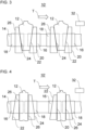
- the Figures 1 and 2 show a section of a device 10 for transporting objects 12 along a transport path or in a transport direction T.
- the objects 12 are preferably designed as containers. However, other objects 12 can also be transported. Particularly preferably, the device 10 is incorporated into a container treatment system. In the container treatment system, the objects 12 designed as containers can be transported by the device 10, for example, to and/or away from treatment stations.
- the device 10 can transport the objects 12, preferably designed as containers, to the several treatment stations and/or hold them during treatment by the treatment stations and/or transport them away after treatment.
- the device 10 has at least one guide track 14 and several movement devices 16, 18 for transporting the objects 12 along the transport path T.
- the at least one guideway 14 is preferably closed or circumferential.
- the at least one guideway 14 can be circular, annular, oval, or elliptical.
- the movement devices 16, 18 are guided and preferably supported on the at least one guide track 14.
- the movement devices 16, 18 can each have at least one guide element (not shown) that guides the respective movement device 16, 18 along the at least one guide track 14.
- the guide elements can be designed, for example, as rollers that roll along the at least one guide track 14 or as sliding blocks that slide along the at least one guide track 14.
- the movement devices 16, 18 can be moved or driven individually or independently of one another along the at least one guide track 14.
- the device 10 can comprise a linear motor system (not shown), e.g., a long-stator linear motor system or a short-stator linear motor system, for individually driving the movement devices 16, 18.
- a long-stator linear motor system several long-stator segments, each having several electromagnets, can be arranged along the at least one guideway 14.
- the long-stator segments can enter into magnetic interaction with permanent magnets of the movement devices 16, 18 in order to individually drive or move the movement devices 16, 18 along the at least one guideway 14.
- several permanent magnets can be arranged along the at least one guideway 14, and the movement devices 16, 18 can each have at least one electromagnet, which can enter into magnetic interaction with the permanent magnets to drive the movement devices 16, 18.
- completely different individual drive concepts for the movement devices 16, 18 are also conceivable, e.g., at least one electric motor per movement device 16, 18 that drives rollers of the movement devices 16, 18.
- the movement devices 16, 18 comprise first movement devices 16 and second movement devices 18.
- the first movement devices 16 and the second movement devices 18 are guided alternately one behind the other along the at least one guide track 14, preferably on the same guide track 14.
- a first movement device 16 and a second movement device 18 form a pair for transporting (at least) one object 12. Successive objects 12 can be transported by successive pairs.
- the object 12 can be positioned between the first movement device 16 and the second movement device 18 of the respective pair during transport along the transport path T.
- One of the movement devices 16, 18 of a pair can support the object 12, for example, from the front with respect to the transport path T, and the other of the movement devices 16, 18 of the pair can support the object 12, for example, from the rear with respect to the transport path T.
- the movement devices 16, 18 of a pair can, for example, clamp or hold the object 12 between them.
- the movement devices 16, 18 can transport the object 12 in a suspended or supported manner, e.g., in neck handling for containers or by clamping a body of the object 12.
- the first movement devices 16 differ from the second movement devices 18.
- the difference preferably lies in how and/or where the respective movement device 16, 18 can support the object 12.
- the first movement devices 16 can differ from the second movement devices 18 with respect to an arrangement and/or configuration of a support for the objects 12.
- the first movement devices 16 and the second movement devices 18 differ with regard to the arrangement of the support for the objects 12, as explained in detail below.
- the first movement devices 16 may each have a first support section 20 and a second support section 22 for supporting the objects 12.
- the first support section 20 may be directed or facing in the direction of the transport path T.
- the second support section 22 may be directed or facing opposite to the direction of the transport path T.
- the support sections 20, 22 may be directed opposite to each other.
- the second movement devices 18 can each have a first support section 24 and a second support section 26 for supporting the objects 12.
- the first support section 24 can be directed or facing in the direction of the transport path T.
- the second support section 26 can be directed or facing opposite to the direction of the transport path T.
- the support sections 24, 26 can be directed opposite to each other.
- the first support section 20 of the first movement device 16 can cooperate with the second support section 26 of the second movement device 18 for transporting an object 12, as shown in Figure 2
- the second support section 22 of the first movement device 16 can cooperate with the first support section 24 of the second movement device 18 for transporting an object 12, as shown in Figure 1 is shown.
- the support sections 20, 22, 24, and 26 can be structurally identical. However, it is also possible, for example, for the support sections 20, 22 to have different structural designs, and for the support sections 24, 26 to also have different structural designs. Preferably, the support sections 20 and 26 are structurally identical, and the support sections 22 and 24 are also structurally identical.
- the support sections 20, 22, 24 and/or 26 can, for example, be V-shaped, as in Figure 1 It is also possible for the support sections 20, 22, 24 and/or 26 to be designed differently, for example, in the shape of a ring segment or planar.
- the first support portions 20 of the first moving devices 16 may be set back with respect to the direction of the transport path T, and the second support portions 26 of the second moving devices 18 may be set back to a direction opposite to the direction of the transport path T, as shown in Figure 1
- the second support portions 22 of the first moving devices 16 may be projecting in a direction opposite to the direction of the transport path T
- the first support portions 24 of the second moving devices 18 may be projecting with respect to the direction of the transport path T, as also shown in Figure 1 is shown.
- the movement devices 16, 18 can each have a support arm 28, 30.
- the support arms 28, 30 can be offset in opposite directions from a respective base.
- the support arm 28 can support the first support section 20 and the second support section 22 of the respective first movement device 16, preferably at an outer end of the support arm 28.
- the support arm 30 can support the first support section 24 and the second support section 26 of the respective second movement device 18, preferably at an outer end of the support arm 30.
- the support arm 28 can be cranked opposite to the direction of the transport path T, starting from a base of the support arm 28 towards an end of the support arm 30 carrying the support sections 20, 22.
- the support arm 30 can be cranked towards the direction of the transport path T, starting from a base of the support arm 30 towards an end of the support arm 30 carrying the support sections 24, 26.
- the movement devices 16 and/or 18 each have two support arms (not shown in the figures), one of which supports the respective first support section 20 or 24 and the other of which supports the respective second support section 22 or 26.
- the support arm that supports the first support section 20 can be cranked from a base, preferably opposite to the direction of the transport path T.
- the support arm that supports the second support section 22 can be cranked from a base, preferably opposite to the direction of the transport path T.
- the support arm that supports the first support section 24 can be cranked from a base, preferably towards the direction of the transport path T.
- the support arm that supports the second support section 26 can be cranked from a base, preferably towards the direction of the transport path T.
- a movement of the movement devices 16, 18 can be controlled by a control unit 32.
- the control unit 32 can control an electrical power supply to the electromagnets of the linear drive (e.g., a long-stator linear drive or a short-stator linear drive) driving the movement devices 16, 18 as desired to effect the individual movement of the movement devices 16, 18.
- the linear drive e.g., a long-stator linear drive or a short-stator linear drive
- the control unit 32 is configured to selectively operate the device 10 in a first operating mode and in a second operating mode.
- Figure 1 shows the operation in the first operating mode.
- the Figure 2 shows the operation in the second operating mode.
- the control unit 32 can control the device 10 for transporting objects 12 of a first format in the first Operating mode, see Figure 1 , and to transport objects 12 of a second format in the second operating mode, see Figure 2
- the first format may differ from the second format, e.g., with respect to a shape and/or size of the objects.
- the objects 12 transported in the first operating mode may be smaller or have a smaller diameter than the objects 12 transported in the second operating mode.
- the objects 12 are each transported by a pair of one of the first moving devices 16 and one of the second moving devices 18.
- the pairs differ between the first operating mode and the second operating mode.
- the pairs are formed such that the first movement device 16 is positioned in front of the second movement device 18 of the respective pair in the direction of the transport path T.
- the front, first movement device 16 of the respective pair can support the respective object 12 from the front with respect to the direction of the transport path T
- the rear, second movement device 18 of the respective pair can support the respective object 12 from the rear with respect to the direction of the transport path T.
- the objects 12 can each be supported between the second support section 22 of the first movement devices 16 and the first support section 24 of the second movement devices 18.
- the pairs are formed such that the second movement device 18 is positioned in front of the first movement device 16 of the respective pair in the direction of the transport path T.
- the front, second movement device 18 of the respective pair can support the respective object 12 from the front with respect to the direction of the transport path T
- the rear, first movement device 16 of the respective pair can support the respective object 12 from the rear with respect to the direction of the transport path T.
- the objects 12 can each be supported between the second support section 26 of the second movement devices 18 and the first support section 20 of the first movement devices 16.
- the different offsets of the support arms 28, 30 described as an example can allow for a smaller extension of the respective pairs, including the respective transported object 12, than would be possible without offsets, particularly in the second operating mode. This allows for the smallest possible separation when transporting large objects.
- FIGS. 3 and 4 show a further device 10' for transporting objects 12 in a first operating mode (see Figure 3 ) and in a second operating mode (see Figure 4 ).
- the device 10' is similar to the device 10 of Figures 1 and 2 executed, so that in the following particular reference is made to modifications of the device 10' compared to the device 10.
- the first movement devices 16 differ from the second movement devices 18 of the device 10' with respect to the configuration or construction of a support for the objects 12.
- Support sections 20 and 22 are structurally different, and support sections 24 and 26 may also be structurally different.
- support sections 20 and 26 are structurally identical, and support sections 22 and 24 are also structurally identical.
- the support sections 20 and 26 can be designed as planar or ring-segment-shaped, vertical support surfaces.
- the support sections 22 and 24 can be designed, for example, as planar or cone-segment-shaped support surfaces. This advantageously allows, for example, tapered or at least partially conical objects 12 to be transported in the first operating mode, and cylindrical or cuboid-shaped objects 12 to be transported in the second operating mode.
- the Figure 5 shows a section of a device 110 for transporting objects 12.
- the objects 12 are preferably designed as containers. However, other objects 12 can also be transported.
- the device 110 is included in a container treatment plant, as already described, for example, with reference to Figure 1 was described.
- the device 110 has at least one guide track 114, 115 and several movement devices 116 for transporting the objects 12 along the transport path T.
- the at least one guide track 114, 115 is preferably closed or circumferential.
- the at least one guide track 114, 115 can be circular, annular, oval, or elliptical.
- it comprises a first guide track 114 and a second guide track 115, which extend essentially parallel and are arranged, for example, one above the other.
- the movement devices 116 are guided and preferably supported on the at least one guide track 114, 115, as already described, for example, with reference to Figure 1 was described.
- the movement devices 116 can be moved or driven individually or independently of one another along the at least one guideway 114, 115.
- the device 110 can have at least one linear motor system (not shown), e.g., a long-stator linear motor system or a short-stator linear motor system, for individually driving the movement devices 116.
- a linear motor system not shown
- Control of the drive of the movement devices 116 can be carried out by a control unit 132.
- first linear motor system e.g., a long-stator linear motor system or a short-stator linear motor system
- first guideway 114 for individually driving those movement devices 116 that are guided along the first guideway 114.
- a second linear motor system e.g., a long-stator linear motor system or a short-stator linear motor system, to be assigned to the second guideway 115 for individually driving those movement devices 116 that are guided along the second guideway 115.
- the movement devices 116 can each have a support section 120 for supporting the object 12.
- the support sections 120 of the three movement devices 116 of the respective groups can support the object at different locations.
- the support sections 120 can, for example, be V-shaped, ring-segment-shaped, or planar.
- the support sections 120 can preferably be carried by a support arm of the respective movement device 116.
- the control unit 132 can be configured to control the plurality of movement devices 116 such that a group G1, G2, G3 of three of the plurality of movement devices 116 together transports an object 12 positioned between them, preferably clamped, along the transport path T up to a transfer area of the device 110 for transferring the object 12, e.g. to another conveyor or to a treatment station.
- the object 12 is preferably held or supported in a three-point support by the three movement devices 116 (or by their support sections 120) of the respective group G1, G2, G3.
- the support sections 120 of the three movement devices 116 of the group G1, G2, G3 can preferably support the object 12 at different height positions.
- a shoulder, a middle section, and a bottom section of the object 12 embodied as a container can be supported with the three support sections 120.
- the movement devices 116 of a group can, for example, clamp or hold the object 12 between them.
- the movement devices 116 can transport the object 12 in a suspended or supported manner, e.g., in neck handling for containers or by clamping a body of the object 12.
- the excerpt from Figure 5 shows three groups G1, G2, G3, each with three movement devices 116.
- the groups G1, G2, G3 can be formed, for example, as follows.
- one of the three movement devices 116 can be guided on the first guide track 114 and the other two movement devices 116 can be guided on the second guide track 115.
- the second group G2 which can directly follow the first group G1 with respect to the direction of the transport path T, two of the three movement devices 116 can be guided on the first guide track 114 and the other movement device 116 can be guided on the second guide track 115.
- the third group G3, which can directly follow the second group G2 with respect to the direction of the transport path T, can in turn be formed like the first group G1, etc.
- Groups such as the first group G1 and the second group G2 can be formed alternately along the direction of the transport path T.
- the Figure 6 shows a further device 110', which is modified compared to the device 110 in particular as follows.
- the control unit 132 can be configured to control the plurality of movement devices 116 such that a group G1, G2 of four of the plurality of movement devices 116 together transports an object 12 positioned between them, preferably clamped, along the transport path T up to a transfer area of the device 110 for transferring the object 12, e.g. to another conveyor or to a treatment station.
- the object 12 is preferably held or supported in a four-point mounting by the four movement devices 116 (or by their support sections 120) of the respective group G1, G2.
- the support sections 116 of the four movement devices 116 of the group G1, G2 can preferably support the object 12 at least partially at different height positions.
- the device 110 and 110' of the Figures 5 and 6 can support the transport of different formats of the objects 12 by adjusting an arrangement of the three or four movement devices 116 of the respective group G1, G2, G3 relative to one another by the control unit 132 depending on the respective format of the object 12 to be transported.
Landscapes
- Engineering & Computer Science (AREA)
- Mechanical Engineering (AREA)
- Non-Mechanical Conveyors (AREA)
- Attitude Control For Articles On Conveyors (AREA)
- Auxiliary Devices For And Details Of Packaging Control (AREA)
Applications Claiming Priority (2)
| Application Number | Priority Date | Filing Date | Title |
|---|---|---|---|
| DE102021129702.8A DE102021129702A1 (de) | 2021-11-15 | 2021-11-15 | Transport von Gegenständen mit unterschiedlichen Formaten |
| EP22207110.2A EP4180371B1 (fr) | 2021-11-15 | 2022-11-14 | Transport d'articles de formats differents |
Related Parent Applications (2)
| Application Number | Title | Priority Date | Filing Date |
|---|---|---|---|
| EP22207110.2A Division-Into EP4180371B1 (fr) | 2021-11-15 | 2022-11-14 | Transport d'articles de formats differents |
| EP22207110.2A Division EP4180371B1 (fr) | 2021-11-15 | 2022-11-14 | Transport d'articles de formats differents |
Publications (2)
| Publication Number | Publication Date |
|---|---|
| EP4559848A2 true EP4559848A2 (fr) | 2025-05-28 |
| EP4559848A3 EP4559848A3 (fr) | 2025-07-30 |
Family
ID=84331867
Family Applications (2)
| Application Number | Title | Priority Date | Filing Date |
|---|---|---|---|
| EP22207110.2A Active EP4180371B1 (fr) | 2021-11-15 | 2022-11-14 | Transport d'articles de formats differents |
| EP25170037.3A Pending EP4559848A3 (fr) | 2021-11-15 | 2022-11-14 | Transport d'articles de formats differents |
Family Applications Before (1)
| Application Number | Title | Priority Date | Filing Date |
|---|---|---|---|
| EP22207110.2A Active EP4180371B1 (fr) | 2021-11-15 | 2022-11-14 | Transport d'articles de formats differents |
Country Status (4)
| Country | Link |
|---|---|
| US (1) | US12110193B2 (fr) |
| EP (2) | EP4180371B1 (fr) |
| CN (1) | CN116119328A (fr) |
| DE (1) | DE102021129702A1 (fr) |
Families Citing this family (4)
| Publication number | Priority date | Publication date | Assignee | Title |
|---|---|---|---|---|
| JP2011502484A (ja) | 2007-11-01 | 2011-01-27 | メイヨ・ファウンデーション・フォー・メディカル・エデュケーション・アンド・リサーチ | Hla−dr結合性ペプチドおよびそれらの使用 |
| DE102023100148A1 (de) | 2023-01-04 | 2024-07-04 | Multivac Sepp Haggenmüller Se & Co. Kg | Greifereinrichtung sowie Verfahren zum Ergreifen und Transportieren von Objekten |
| DE102023123402A1 (de) * | 2023-08-30 | 2025-03-06 | Krones Aktiengesellschaft | Sternradförderer zum Fördern von Behältern in einer Getränkeabfüllanlage |
| EP4610203A1 (fr) * | 2024-02-28 | 2025-09-03 | Rotzinger PharmaPack GmbH | Dispositif et procédé de transport |
Citations (2)
| Publication number | Priority date | Publication date | Assignee | Title |
|---|---|---|---|---|
| EP3109189A1 (fr) | 2015-06-25 | 2016-12-28 | Sidel Participations | Dispositif de transfert pour transporter des unités d'emballage |
| WO2019159116A1 (fr) | 2018-02-19 | 2019-08-22 | Makro Labelling S.R.L. | Machine de traitement ou de transport de conteneurs |
Family Cites Families (24)
| Publication number | Priority date | Publication date | Assignee | Title |
|---|---|---|---|---|
| DE2819622A1 (de) | 1978-05-05 | 1979-11-08 | Festo Maschf Stoll G | Greifzange fuer manipulatoren, roboter o.dgl. |
| US6371717B1 (en) * | 2000-05-11 | 2002-04-16 | Abb Automation Inc. | Device for mechanically gripping and loading cylindrical objects |
| DE102008040204A1 (de) * | 2008-07-07 | 2010-01-14 | Robert Bosch Gmbh | Vorrichtung und Verfahren zum Transportieren von Produkten mit Linearantrieb |
| EP2653036B1 (fr) | 2012-04-18 | 2019-04-03 | Albert Handtmann Maschinenfabrik GmbH & Co. KG | Procédé et dispositif de suspension de saucisses |
| EP2743192B1 (fr) * | 2012-12-12 | 2016-09-14 | Tetra Laval Holdings & Finance S.A. | Unité de séquençage et de guidage d'éléments |
| DE102013218397B4 (de) * | 2013-09-13 | 2024-07-04 | Krones Ag | Vorrichtung und Verfahren zum Gruppieren von Behältern |
| TW201620805A (zh) * | 2014-10-21 | 2016-06-16 | 康寧公司 | 玻璃片處理設備及方法 |
| EP3034441B1 (fr) * | 2014-12-17 | 2017-04-19 | UHLMANN PAC-SYSTEME GmbH & Co. KG | Dispositif de transport de produits |
| DE102017102914A1 (de) | 2017-02-14 | 2018-08-16 | Sig Technology Ag | Verpackungsmaschine sowie Verfahren zum Betreiben einer Verpackungsmaschine |
| JP7214314B2 (ja) * | 2017-12-06 | 2023-01-30 | 株式会社京都製作所 | リニア搬送装置 |
| JP7105571B2 (ja) * | 2018-01-31 | 2022-07-25 | Pacraft株式会社 | 袋体処理機 |
| CN108190512B (zh) * | 2018-02-09 | 2024-11-08 | 北矿机电科技有限责任公司 | 一种电沉积金属阴极板的链条运输系统 |
| DE102018203626B3 (de) | 2018-03-09 | 2019-08-14 | Kuka Systems Gmbh | Mehrfachgreifervorrichtung für einen Roboter |
| ES2725300B2 (es) * | 2018-03-21 | 2021-12-16 | Valles Tomas Mulet | Maquina y procedimiento para posicionar objetos. |
| CN208867495U (zh) * | 2018-09-11 | 2019-05-17 | 东莞智昊光电科技有限公司 | 夹持机械手 |
| DE102019104088A1 (de) | 2019-02-19 | 2020-08-20 | Volker Till | Abfüllanlage und Verfahren zur bedarfsangepassten Befüllung von Flaschen |
| EP3744649B1 (fr) * | 2019-05-27 | 2021-07-07 | Mespack, S.L. | Dispositif de transport pour transporter des récipients souples le long d'une ligne d'emballage |
| IT201900010536A1 (it) * | 2019-07-01 | 2021-01-01 | Ima Spa | Macchina e procedimento per trasportare automaticamente uno o piu’ componenti per realizzare una confezione da e verso una o piu’ stazioni di lavorazione. |
| IT201900022404A1 (it) * | 2019-11-28 | 2021-05-28 | Ct Pack Srl | Sistema di trasferimento articoli per macchina confezionatrice, macchina confezionatrice, procedimento e prodotto informatico corrispondenti. |
| JP7390907B2 (ja) * | 2020-01-29 | 2023-12-04 | 株式会社京都製作所 | 搬送装置 |
| US11697556B2 (en) * | 2020-02-07 | 2023-07-11 | Packsize Llc | Dynamic conveyor system for custom sized packaging |
| JP7369079B2 (ja) * | 2020-04-01 | 2023-10-25 | 株式会社京都製作所 | リニア搬送装置 |
| IT202000008479A1 (it) * | 2020-04-21 | 2021-10-21 | Kosme Srl Unipersonale | Dispositivo di trasporto per il trasporto di contenitori |
| CN112475954A (zh) * | 2020-11-20 | 2021-03-12 | 盐城市鑫海机械有限公司 | 曲轴用定位夹具 |
-
2021
- 2021-11-15 DE DE102021129702.8A patent/DE102021129702A1/de active Pending
-
2022
- 2022-11-11 US US17/985,522 patent/US12110193B2/en active Active
- 2022-11-14 EP EP22207110.2A patent/EP4180371B1/fr active Active
- 2022-11-14 EP EP25170037.3A patent/EP4559848A3/fr active Pending
- 2022-11-15 CN CN202211429197.1A patent/CN116119328A/zh active Pending
Patent Citations (2)
| Publication number | Priority date | Publication date | Assignee | Title |
|---|---|---|---|---|
| EP3109189A1 (fr) | 2015-06-25 | 2016-12-28 | Sidel Participations | Dispositif de transfert pour transporter des unités d'emballage |
| WO2019159116A1 (fr) | 2018-02-19 | 2019-08-22 | Makro Labelling S.R.L. | Machine de traitement ou de transport de conteneurs |
Also Published As
| Publication number | Publication date |
|---|---|
| EP4180371A1 (fr) | 2023-05-17 |
| EP4180371B1 (fr) | 2025-05-21 |
| EP4180371C0 (fr) | 2025-05-21 |
| US12110193B2 (en) | 2024-10-08 |
| US20230150776A1 (en) | 2023-05-18 |
| CN116119328A (zh) | 2023-05-16 |
| DE102021129702A1 (de) | 2023-05-17 |
| EP4559848A3 (fr) | 2025-07-30 |
Similar Documents
| Publication | Publication Date | Title |
|---|---|---|
| EP4180371B1 (fr) | Transport d'articles de formats differents | |
| EP3980357B1 (fr) | Procédé et dispositif de distribution et/ou de groupement de récipients | |
| DE102015103833B3 (de) | Verbessertes Transportsystem, insbesondere für eine Füll- und Verschließanlage für pharmazeutische oder kosmetische Objekte | |
| EP2689933B1 (fr) | Dispositif et procédé destinés à l'équipement de récipients et machine de base | |
| DE102014218313B4 (de) | Transportvorrichtung für in einer Bearbeitungsmaschine zu bearbeitende und/oder dort bearbeitete Objekte | |
| EP3573910A1 (fr) | Installation de traitement de contenants et procédé de transport d'éléments fonctionnels dans une installation de traitement de contenants destinée à traiter des contenants | |
| DE102020120295A1 (de) | Vorrichtung zum Ausstatten von Behältern | |
| EP4289771A1 (fr) | Dispositif pour transporter des récipients et son utilisation | |
| DE102015224975A1 (de) | Behandlungsmaschine für Behälter | |
| EP2874939A2 (fr) | Installation de production modulaire et procédé de fabrication et/ou de remplissage de récipients | |
| DE102022119231A1 (de) | Vorrichtung und Verfahren zum Transportieren von Behältern | |
| DE102019204540A1 (de) | Puffervorrichtung und Verfahren zum Puffern von Behältern | |
| EP3932838A1 (fr) | Procédé et système de transport permettant de manipuler des marchandises de détail sur une voie de transport | |
| EP3331769A1 (fr) | Dispositif de blocage pour une unité de maintien et de centrage | |
| DE102014218308A1 (de) | Transportvorrichtung für in einer Bearbeitungsmaschine zu bearbeitende und/oder dort bearbeitete Objekte | |
| DE102014218310A1 (de) | Transportvorrichtung für in einer Bearbeitungsmaschine zu bearbeitende und/oder dort bearbeitete Objekte | |
| DE102022108754A1 (de) | Behälterbehandlungsanlage | |
| DE102020117827B3 (de) | Förderanlage mit linearen Achsvorrichtungen | |
| DE102013217202A1 (de) | Vorrichtung mit andockbaren Druckmodulen | |
| DE102021100025A1 (de) | Vorrichtung und Verfahren zum Puffern von Objekten, vorzugsweise Behältern | |
| WO2022144182A1 (fr) | Dispositif et procédé d'étiquetage d'objets | |
| DE102020132134A1 (de) | Direktdruckmaschine | |
| EP1655227A1 (fr) | Dispositif pour déballer de conteneurs hors de la caisse de transport | |
| DE102014218314A1 (de) | Verfahren zum Betreiben einer Transportvorrichtung für mehrere in einer Bearbeitungsmaschine zu bearbeitende und/oder dort bearbeitete Objekte | |
| EP4001189A1 (fr) | Dispositif de traitement de récipients |
Legal Events
| Date | Code | Title | Description |
|---|---|---|---|
| PUAI | Public reference made under article 153(3) epc to a published international application that has entered the european phase |
Free format text: ORIGINAL CODE: 0009012 |
|
| STAA | Information on the status of an ep patent application or granted ep patent |
Free format text: STATUS: THE APPLICATION HAS BEEN PUBLISHED |
|
| AC | Divisional application: reference to earlier application |
Ref document number: 4180371 Country of ref document: EP Kind code of ref document: P |
|
| AK | Designated contracting states |
Kind code of ref document: A2 Designated state(s): AL AT BE BG CH CY CZ DE DK EE ES FI FR GB GR HR HU IE IS IT LI LT LU LV MC ME MK MT NL NO PL PT RO RS SE SI SK SM TR |
|
| PUAL | Search report despatched |
Free format text: ORIGINAL CODE: 0009013 |
|
| AK | Designated contracting states |
Kind code of ref document: A3 Designated state(s): AL AT BE BG CH CY CZ DE DK EE ES FI FR GB GR HR HU IE IS IT LI LT LU LV MC ME MK MT NL NO PL PT RO RS SE SI SK SM TR |
|
| RIC1 | Information provided on ipc code assigned before grant |
Ipc: B65G 54/02 20060101AFI20250623BHEP |
|
| STAA | Information on the status of an ep patent application or granted ep patent |
Free format text: STATUS: REQUEST FOR EXAMINATION WAS MADE |
|
| 17P | Request for examination filed |
Effective date: 20260130 |