EP4559853A1 - Verfahren und vorrichtung zur erkennung der automatischen schliessfunktion einer oder mehrerer schachttüren - Google Patents
Verfahren und vorrichtung zur erkennung der automatischen schliessfunktion einer oder mehrerer schachttüren Download PDFInfo
- Publication number
- EP4559853A1 EP4559853A1 EP24213638.0A EP24213638A EP4559853A1 EP 4559853 A1 EP4559853 A1 EP 4559853A1 EP 24213638 A EP24213638 A EP 24213638A EP 4559853 A1 EP4559853 A1 EP 4559853A1
- Authority
- EP
- European Patent Office
- Prior art keywords
- door
- landing
- landing door
- detected
- car door
- Prior art date
- Legal status (The legal status is an assumption and is not a legal conclusion. Google has not performed a legal analysis and makes no representation as to the accuracy of the status listed.)
- Pending
Links
Images



Classifications
-
- B—PERFORMING OPERATIONS; TRANSPORTING
- B66—HOISTING; LIFTING; HAULING
- B66B—ELEVATORS; ESCALATORS OR MOVING WALKWAYS
- B66B5/00—Applications of checking, fault-correcting, or safety devices in elevators
- B66B5/0006—Monitoring devices or performance analysers
- B66B5/0018—Devices monitoring the operating condition of the elevator system
- B66B5/0025—Devices monitoring the operating condition of the elevator system for maintenance or repair
-
- B—PERFORMING OPERATIONS; TRANSPORTING
- B66—HOISTING; LIFTING; HAULING
- B66B—ELEVATORS; ESCALATORS OR MOVING WALKWAYS
- B66B5/00—Applications of checking, fault-correcting, or safety devices in elevators
- B66B5/0006—Monitoring devices or performance analysers
- B66B5/0018—Devices monitoring the operating condition of the elevator system
- B66B5/0031—Devices monitoring the operating condition of the elevator system for safety reasons
-
- B—PERFORMING OPERATIONS; TRANSPORTING
- B66—HOISTING; LIFTING; HAULING
- B66B—ELEVATORS; ESCALATORS OR MOVING WALKWAYS
- B66B5/00—Applications of checking, fault-correcting, or safety devices in elevators
- B66B5/0006—Monitoring devices or performance analysers
- B66B5/0018—Devices monitoring the operating condition of the elevator system
-
- B—PERFORMING OPERATIONS; TRANSPORTING
- B66—HOISTING; LIFTING; HAULING
- B66B—ELEVATORS; ESCALATORS OR MOVING WALKWAYS
- B66B13/00—Doors, gates, or other apparatus controlling access to, or exit from, cages or lift well landings
- B66B13/02—Door or gate operation
- B66B13/14—Control systems or devices
- B66B13/143—Control systems or devices electrical
-
- B—PERFORMING OPERATIONS; TRANSPORTING
- B66—HOISTING; LIFTING; HAULING
- B66B—ELEVATORS; ESCALATORS OR MOVING WALKWAYS
- B66B13/00—Doors, gates, or other apparatus controlling access to, or exit from, cages or lift well landings
- B66B13/02—Door or gate operation
- B66B13/14—Control systems or devices
- B66B13/143—Control systems or devices electrical
- B66B13/146—Control systems or devices electrical method or algorithm for controlling doors
-
- B—PERFORMING OPERATIONS; TRANSPORTING
- B66—HOISTING; LIFTING; HAULING
- B66B—ELEVATORS; ESCALATORS OR MOVING WALKWAYS
- B66B13/00—Doors, gates, or other apparatus controlling access to, or exit from, cages or lift well landings
- B66B13/30—Constructional features of doors or gates
-
- B—PERFORMING OPERATIONS; TRANSPORTING
- B66—HOISTING; LIFTING; HAULING
- B66B—ELEVATORS; ESCALATORS OR MOVING WALKWAYS
- B66B5/00—Applications of checking, fault-correcting, or safety devices in elevators
- B66B5/0006—Monitoring devices or performance analysers
- B66B5/0037—Performance analysers
Definitions
- the present application relates to elevator technology and, in particular, to a method and device for detecting an automatic closing function of one or more landing doors, and a non-transitory computer-readable storage medium storing a computer program for implementing the method.
- the landing door When a landing door is not properly closed and a car is not in a proper position for that floor, the landing door will be locked or closed automatically with the help of a self-locking function or an automatic closing function to reduce the risk of accidents.
- the check of the automatic closing function of the landing door is still manually completed. For example, maintenance personnel regularly or irregularly test the automatic closing function of the landing door on each floor one by one to determine whether its function is normal. The check work will take a large amount of labor and time, especially for elevator systems operating in high-rise and ultra-high-rise buildings.
- a method for detecting an automatic closing function of one or more landing doors In the method, a state variable of a drive mechanism of the elevator system is first obtained when a car door of a car of an elevator system and a landing door to be detected move in a uniform linear motion during a closing process.
- the state variable is suitable for determining a driving force applied by the drive mechanism to the car door and the landing door to be detected.
- automatic closing capability of the landing door to be detected is determined based on the driving force applied during the uniform linear motion and resistance to which the car door is subjected when traveling.
- Particular embodiments further may include at least one, or a plurality of, the following optional features, alone or in combination with each other:
- the method further comprises: determining whether the elevator system is suitable for entering or being in a detection mode, and if so, performing steps A and B.
- the method further comprises: sending a detection result regarding the automatic closing capability of the landing door to be detected to a cloud platform or a mobile terminal.
- steps A and B are performed for a plurality of landing doors in a specified order.
- step A comprises: A1. when the car stops at one of a plurality of floors corresponding to the landing door to be detected, opening the car door of the car and the landing door to be detected; A2. causing the car door and the landing door to be detected to move in the uniform linear motion during the closing process by controlling the driving force applied by the drive mechanism to the car door and the landing door to be detected.
- step A comprises receiving, from the elevator system, the state variable of the drive mechanism when the car door and the landing door to be detected move in the uniform linear motion.
- step A comprises: A3. Receiving, from the elevator system, state variables of the drive mechanism under various motion states of the car door and the landing door to be detected ; A4. extracting the state variable when the car door and the landing door to be detected move in the uniform linear motion from the state variables under the various motion states.
- step B is performed at any of the following locations: a cloud platform, an elevator controller, a door controller and a mobile terminal.
- a speed of the uniform linear motion is controlled in a range of 20 mm/sec to 80 mm/sec.
- the drive mechanism is a motor
- step A2 the uniform linear motion of the car door and the landing door to be detected is realized by causing the motor to work in a constant-speed output mode.
- the state variable when the car door and the landing door to be detected move in the uniform linear motion and the state variable under various motion states are an induced current or an output torque of the motor.
- the resistance is determined in the following manner: decoupling the car door and the landing door to be detected from mechanical coupling; placing the car door in a state of the uniform linear motion by controlling the driving force applied by the drive mechanism to the car door; and determining the resistance based on the driving force applied to the car door in the state of the uniform linear motion.
- the automatic closing capability is measured in terms of a net force applied to the landing door to be detected.
- the automatic closing capability of the landing door to be detected is determined in the following manner: B1. determining, from the state variable, the driving force applied by the drive mechanism when the landing door to be detected moves in the uniform linear motion; B2. determining the net force based on the driving force applied by the drive mechanism when the landing door to be detected moves in the uniform linear motion and the resistance to which the car door is subjected when traveling; and B3. determining that the landing door to be detected can be closed normally if the net force is greater than or equal to a preset value, otherwise determining that the landing door to be detected cannot be closed normally.
- an average value of the driving force applied by the drive mechanism at a plurality of moments when the car door and the landing door to be detected move in the uniform linear motion is used as the driving force for determining the net force.
- a device for detecting an automatic closing function of one or more landing doors comprises at least one memory, at least one processor coupled with the memory and a computer program stored on the memory and running on the processor.
- the running of the computer program results in the following operations: A. obtaining a state variable of a drive mechanism of the elevator system when a car door of a car of an elevator system and a landing door to be detected move in a uniform linear motion during a closing process, the state variable being suitable for determining a driving force applied by the drive mechanism to the car door and the landing door to be detected; B. determining automatic closing capability of the landing door to be detected based on the driving force applied during the uniform linear motion and resistance to which the car door is subjected when traveling.
- Particular embodiments further may include at least one, or a plurality of, the above mentioned optional features, alone or in combination with each other.
- a computer-readable storage medium on which a computer program suitable for running on a processor of a terminal device is stored, the running of the computer program resulting in the steps of the method as described above being performed.
- closing process refers to a process in which a car door or landing door begins to move until it is normally closed or reaches a closed state. During the closing process, the car door or landing door gradually decreases a gap between the doors. During the closing process, the car door or landing door gradually decreases the gap between the doors until it is normally closed.
- the normal closing described herein refers to the car door or landing door being completely closed without gaps or openings. It should be noted that the gap described herein may refer to the gap between door leaves (when the door contains multiple door leaves), or may refer to the gap between door leaf and door frame (when the door only contains one door leaf).
- automatic closing function of a landing door refers to a function that causes the landing door to close, prohibits the opening of the landing door, or locks the landing door when an elevator system is in a specific state (e.g., when the car is not on this floor and the landing door is completely closed). It should be noted that the implementation of the automatic closing function of the landing door is dependent on a cooperative operation of multiple levels and multiple components.
- a control device e.g., a door controller or elevator controller
- a door sensor or door lock switch is responsible for transmitting the state signal of the landing door (e.g., a door closing in place signal) to the control device
- an executing mechanism is a key component that usually executes actions to close, lock, or unlock the landing door based on instructions from the control device.
- any abnormal operation of any level or component may result in abnormal automatic closing function of a landing door.
- spring aging or loss of counterweight will make the driving force no longer exist, foreign objects inside the door guide rail will impede the door movement, and friction will increase when the door wheels are adhering to oil, all of which will cause the door not to close normally.
- the specific structure and working principle of the executing mechanism may vary depending on the elevator manufacturer and product model, and the executing mechanism usually includes components such as a spring device and/or a counter weight for ensuring normal operation of the self-locking function or the automatic closing function.
- the executing mechanism when the landing door is in a closed state, the spring will apply a certain force to the landing door to drive it into a completely closed state and keep it tightly closed.
- Counter weight is another component in the executing mechanism, which uses gravity to drive the landing door into a completely closed state and keep it locked.
- a separate counter weight or spring may usually be configured for each landing door.
- the drive mechanism of the elevator system drives the movement of the car door and landing door.
- a drive mechanism such as a motor or a hydraulic system may usually be utilized to provide the force or driving force for driving the movement of the car door and landing door.
- the force applied to the landing door by the executing mechanism described above e.g. spring device, counter weight, etc.
- the resistance e.g. the friction between the car door and the landing door and the door frame
- F 1 is the force applied to the landing door by the executing mechanism
- F 2 is the driving force applied by the drive mechanism to the car door and the landing door
- f landing is the resistance (e.g. the friction between the landing door and the door frame) to which the landing door is subjected in the process of traveling
- f car is the resistance (e.g. the friction between the car door and the door frame) to which the car door is subjected in the process of traveling
- m is the sum of the masses of the car door and the landing door
- a is the acceleration of the car door and the landing door as a whole.
- the inventors of the present application have found through research that there is a significant correlation between the magnitude of the net force F net (which is equal to F 1 -f landing ) applied to the landing door and the automatic closing capability of the landing door (the automatic closing capability determines whether the landing door can be auto-closed or whether the automatic closing function is normal or not).
- the net force applied to the landing door is utilized as a measure of this automatic closing capability.
- the judgment may be based on a single threshold value, i.e., the net force F net is compared to a preset value TH, and when the former is greater than or equal to the latter, it is judged that the landing door can be closed normally, and vice versa, it is judged that the landing door cannot be closed normally.
- the above preset value TH may be determined based on a field experiment or a simulation experiment. It is to be noted that the research of the inventors of the present application has shown that a single threshold value is already sufficient to make a good differentiation between the normal or not normal of the automatic closing function, and has a low false alarm rate and a low omission rate for the function abnormality event. This is favorable for the simplification of the judgment logic.
- the automatic closing function detection method described above is not only applicable to a single landing door, but may also be applied to multiple landing doors.
- the detection of the automatic closing function of the landing door of each landing door may be executed sequentially in accordance with the order in the list of landing doors to be maintained, in accordance with the detection method described above, until all landing doors in the list have completed the detection operation.
- the order in which the detection is executed may be various specified orders, such as a floor order including a landing door from the 1 st floor to the nth floor or a landing door from the nth floor to the 1st floor, or an order obtained by randomly selecting from the landing doors of the 1st to the nth floors.
- the above-described detection method is also applicable to the case where a floor contains a plurality of landing doors, in which case a corresponding device identification may be assigned to each of the landing doors to distinguish the landing doors from each other.
- the car door and the landing door may be caused to move in a uniform linear motion during a closing process by controlling the driving force of the drive mechanism.
- the driving force F 2 applied by the drive mechanism to the car door and the landing door may be determined according to the state variables of the drive mechanism.
- the driving force F 2 applied by the motor to the car door and the landing door may be obtained from the induced current as a state variable.
- the output torque of the motor may also be used as a state variable.
- the resistance f car in equation (2) above may be experimentally determined or calibrated.
- it is possible to decouple the car door and the landing door from mechanical coupling i.e., so that the landing door does not move under the drive of the car door
- the driving force F 2 of the drive mechanism acts only on the car door.
- the resistance f car to which the car door is subjected may be determined (e.g., the driving force applied by the drive mechanism in a uniform linear motion may be determined as the resistance f car ) .
- the inventors of the present application have found, after research, that for the same car door, it remains substantially constant or changes very little at various speeds of movement and at various positions of the car door, which makes it possible to determine the resistance without taking into account the influence of factors such as the speed of movement and the position, thus determining the resistance of the car door in an efficient and concise manner.
- the resistance f car may be calibrated regularly or irregularly in the manner described above to reflect changes in the performance of the car door (e.g. changes in friction due to car door wear, etc.).
- Various ways may be used to realize a uniform linear motion of the car door and the landing door by controlling the driving force applied by the drive mechanism to the car door and the landing door.
- the motor usually has a constant-speed output mode, in which the induced current of the motor is adjusted based on a control algorithm such as PID to cause the car door and the landing door to move in a uniform linear motion.
- a control algorithm such as PID to cause the car door and the landing door to move in a uniform linear motion.
- controlling the speed of movement of the car door and the landing door at a low level is advantageous for improving the accuracy of the determination of the automatic closing capability of the landing door.
- a speed of the uniform linear motion of the landing door and the car door may be controlled in the range of 20 mm/sec to 80 mm/sec.
- the door controller and the elevator controller determine whether the landing door can be closed normally based on the driving force of the drive mechanism and the resistance to which the car door is subjected, and subsequently send the determination result to a cloud platform (e.g., via an IoT gateway to a cluster of servers providing cloud computing services) or a mobile terminal (e.g., via a wireless signal transceiver to a mobile terminal such as a cell phone, a tablet, a portable computer, and a wearable device).
- a cloud platform e.g., via an IoT gateway to a cluster of servers providing cloud computing services
- a mobile terminal e.g., via a wireless signal transceiver to a mobile terminal such as a cell phone, a tablet, a portable computer, and a wearable device.
- the determination of the automatic closing capability of the landing door is performed at the cloud platform or the mobile terminal.
- the door controller or elevator controller may actively send state variables of the drive mechanism of the elevator system (e.g., induced current or output torque of the motor, etc.) to the cloud platform or the mobile terminal on a regular or irregular basis, or may provide the state variables to the cloud platform or the mobile terminal in response to a request for accessing data from the cloud platform or the mobile terminal.
- state variables of the drive mechanism of the elevator system e.g., induced current or output torque of the motor, etc.
- the state variables are obtained by controlling the drive mechanism when the car door and the landing door move in a uniform linear motion. It should be noted, however, that this is not the only way.
- the state variables of the drive mechanism when the landing door and the car door are in various operating states are stored by the door controller or the elevator controller; subsequently, the state variables corresponding to the time when the car door and the landing door move in a uniform linear motion may be extracted from the stored state variables for use in the judgment of the automatic closing capability of the landing door. Since it is no longer necessary to put the elevator system into a specific operating mode for obtaining the state variables in the state of uniform linear motion, the workload of upgrading and reconstructing the existing elevator system can be minimized to the greatest extent possible.
- FIG. 1 is a flowchart of a method for detecting an automatic closing function of a landing door in accordance with some embodiments of the present application.
- the method described below may be implemented by various devices, which include, for example, but are not limited to, a control device (e.g., a door controller or an elevator controller) within an elevator system and a dedicated device for detecting the automatic closing function of the landing door, etc., which are hereinafter collectively referred to as a detection device.
- a control device e.g., a door controller or an elevator controller
- a dedicated device for detecting the automatic closing function of the landing door, etc. which are hereinafter collectively referred to as a detection device.
- the method shown in FIG. 1 begins at step 101.
- the detection device determines whether the elevator system is suitable for entering the detection mode at the current time. If it is suitable for entering the detection mode, it proceeds to step 102, otherwise, it continues to wait. Exemplarily, maintenance of the elevator system is typically performed during non-operational period, so the detection device may allow the elevator system to enter the detection mode when the current time is outside of the operational period and there are no calls for elevators.
- the detection device obtains a queue Q of landing doors to be performed for checking the automatic closing function of the landing door
- the queue comprises one or more landing doors FD i , each landing door being associated with one of a plurality of floors (e.g., provide at an associated floor).
- the order of floors e.g. from the 1st floor to the nth floor or from the nth floor to the 1st floor
- the serial number i is used to indicate the order in which the check operation of the automatic closing function of the landing door is performed.
- VAR i e.g., an induced current of the motor
- step 104 the detection device determines whether the state variables VAR 1 ⁇ VAR n of the drive mechanism when all the landing doors in the queue Q move in a uniform linear motion have been obtained, and proceeds to step 105 if all the landing doors in the queue Q are traversed, and otherwise, proceeds to step 106.
- step 105 the detection device sends the state variables VAR 1 ⁇ VAR n obtained in step 104 when each landing door moves in a uniform linear motion to the cloud platform or the mobile terminal.
- the movement speeds V 1 ⁇ V n of the car door and the landing door at the time of obtaining the state variables may be sent together with the state variables.
- step 106 the flow shown in FIG. 1 returns to step 103 so as to perform the state variable obtaining operation on the other landing doors in the queue Q.
- the detection device may judge whether each landing door in the queue can be closed normally based on the state variables VAR 1 ⁇ VAR n obtained in step 104, and send the judgment results to the cloud platform or the mobile terminal.
- the detection device may utilize the judgment logic based on a single threshold value described above to obtain the judgment results.
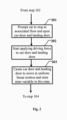
- FIG. 2 is a flowchart of a method for detecting an automatic closing function of a landing door in accordance with some other embodiments of the present application. The implementation of step 103 in FIG. 1 is described further below with the aid of FIG. 2 .
- the detection device also prompts the landing door and the car door to be in the open state.
- step 202 the detection device prompts the drive mechanism (e.g., a motor) to start applying a driving force to the car door CD and the ith landing door FD i , thereby initiating the closing process of the car door and the ith landing door.
- the drive mechanism e.g., a motor
- step 203 under control (e.g., by the door controller) or coordination (e.g., by the door controller based on an instruction from the elevator controller) of the detection device, the car door and the landing door are caused to move in a uniform linear motion by adjusting the driving force applied by the drive mechanism to the car door CD and the landing door FD i , and a state variable VAR i (e.g., induced current of the motor, etc.) of the drive mechanism at the time when the car door CD and the landing door FD i are in the state of uniform linear motion is stored.
- VAR i e.g., induced current of the motor, etc.
- the state variable VAR i may contain either a single sample value or several sample values for the moments t 1 ⁇ t m .
- the driving force F i 2 (t 1 ) ⁇ F i 2 (t m ) applied by the drive mechanism at the plurality of moments when the car door CD and the landing door FD i move in uniform linear motion will be obtained from the state variable, and the average value of these driving forces may be used for the judgment of the automatic closing capability of the landing door FD i (here, the superscript i corresponds to the serial number of the landing door in the queue Q).
- step 203 After completion of step 203, the process shown in FIG. 2 will go, for example, to step 104 in FIG. 1 .
- FIG. 3 is a flowchart of a method for detecting an automatic closing function of a landing door in accordance with some other embodiments of the present application. The method for determining the automatic closing capability of a landing door based on a state variable is described further in the following with the aid of FIG. 3 .
- the driving force F i 2 applied by the motor to the car door and the landing door may be obtained from the induced current as the state variable VAR i based on the correspondence (e.g., proportionality) between the induced current and the output torque of the motor, where the superscript i corresponds to the serial number of the landing door in the queue Q.
- the average value of the driving force F i 2 (t 1 ) ⁇ F i 2 (t m ) applied at the plurality of moments may be used as the driving force F i 2 applied by the motor to the car door and the landing door.
- the detection device determines a net force F i net applied to the landing door FD i based on the driving force F i 2 determined in step 301 and the resistance f car to which the car door CD is subjected to during its travel as calibrated by experimentation, where the superscript i corresponds to the serial number of the landing door in the queue Q.
- the specific determination may for example utilize the equation (2) above.
- step 303 the detection device determines whether the net force F i net is greater than or equal to the preset value TH, and if so, assigns the landing door FD i with the flag TRUE for being able to be closed normally, and otherwise assigns the landing door FD i with the flag FALSE for not being able to be closed normally.
- the corresponding preset value TH i may be set for each landing door to reflect differences in the automatic closing capability requirements of the landing doors.
- step 304 the detection device determines whether a judgment operation has been performed for all the landing doors in the queue Q. If all the landing doors in the queue Q are traversed, it proceeds to step 305, otherwise, it proceeds to step 306.
- step 305 the detection device sends the judgment result regarding the automatic closing capability of the landing doors FD 1 ⁇ FDR n to the cloud platform or the mobile terminal.
- step 306 the flow shown in FIG. 3 returns to step 301 so as to perform the state variable obtaining operation on the other landing doors in the queue Q.
- FIG. 4 is a flowchart of a method for detecting an automatic closing function of a landing door in accordance with some other embodiments of the present application.
- the method described below may be realized at a cloud platform or a mobile terminal.
- the method shown in FIG. 4 begins at step 401.
- the cloud platform or the mobile terminal obtains a state variable associated with each of the landing doors in the queue Q of landing doors.
- the state variables are state variables of the drive mechanism when the car door and the landing door are in a state of uniform linear motion (e.g., state variables VAR 1 to VAR n obtained with the help of the implementation shown in FIG. 2 ).
- the cloud platform or the mobile terminal may extract the state variables (also denoted as VAR 1 ⁇ VAR n for convenience) corresponding to the time when the car door and the landing door move in a uniform linear motion from the set of state variables of the drive mechanism provided by the elevator system in various motion states of the car door and the landing door.
- the manner in which the driving force F i 2 applied by the motor to the car door and the landing door is determined by the state variable VAR i has been described above and will not be repeated here.
- the cloud platform or the mobile terminal determines a net force F i net applied to the landing door based on the driving force F i 2 determined in step 402 and the resistance f car to which the car door CD is subjected to during its travel as calibrated by experimentation.
- the specific manner in which the net force F i net is determined has been described above, and will not be repeated herein.
- the calibrated resistance f car may be sent by the elevator system to the cloud platform or the mobile terminal regularly or irregularly, or it may be called by the cloud platform or the mobile terminal by accessing the elevator system.
- the cloud platform or the mobile terminal compares the net force F i net with the preset value TH, and if it is greater than or equal to the preset value TH, assigns the landing door FD i with the flag TRUE for being able to be closed normally, and otherwise assigns the landing door FD i with the flag FALSE for not being able to be closed normally.
- step 404 the process shown in FIG. 4 proceeds to step 405.
- the cloud platform or the mobile terminal determines whether a judgment operation has been performed for all the landing doors in the queue Q. If all the landing doors in the queue Q are traversed, it proceeds to step 406, otherwise, it proceeds to step 407.
- step 406 the cloud platform or the mobile terminal will generate a detection report on the automatic closing capability of each of the landing doors in the queue Q.
- the flow shown in FIG. 4 returns to step 402 so as to perform the state variable obtaining operation on the other landing doors in the queue Q.
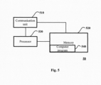
- FIG. 5 is a schematic block diagram of a device for detecting an automatic closing function of a landing door in accordance with some other embodiments of the present application.
- the device shown in FIG. 5 may be one of a cloud platform, an elevator controller, a door controller, and a mobile terminal.
- a device 50 comprises a communication unit 510, one or more memories 520 (e.g., a non-volatile memory such as a flash memory, a ROM, a hard drive, a disk, an optical disc), one or more processors 530, and a computer program 540.
- memories 520 e.g., a non-volatile memory such as a flash memory, a ROM, a hard drive, a disk, an optical disc
- processors 530 e.g., a computer program 540.
- the communication unit 510 serves as a communication interface configured to establish a communication connection between the device 50 and an external device (e.g., a drive mechanism for a car door, etc.) or a network (e.g., Internet and wireless LAN, etc.).
- an external device e.g., a drive mechanism for a car door, etc.
- a network e.g., Internet and wireless LAN, etc.
- the memory 520 stores the computer program 540 that may be executed by the processor 530.
- the memory 520 may also store data generated by the processor 530 in execution of the computer program 540 and data received from an external device via the communication unit 510 (e.g., a queue Q of landing doors to be performed for checking the automatic closing function, a state variable of the drive mechanism, a calibrated value of the resistance to which the car door is subjected, and the detection result of the automatic closing function, etc.).
- the processor 530 is configured to run the computer program 540 stored on the memory 520 and to perform access operations to the memory 520 (e.g., obtaining the queue Q of landing doors, the state variables of the drive mechanism, the calibrated value of the resistance to which the car door is subjected, and storing, for example, the detection result of the automatic closing function, etc., in the memory 520, etc.).
- the computer program 540 may include computer instructions for implementing the methods described with the aid of FIGS. 1 to 4 , enabling the corresponding methods to be implemented when the computer program 540 is run on the processor 530.
Landscapes
- Engineering & Computer Science (AREA)
- Automation & Control Theory (AREA)
- Elevator Door Apparatuses (AREA)
Applications Claiming Priority (1)
| Application Number | Priority Date | Filing Date | Title |
|---|---|---|---|
| CN202311568881.2A CN120024770A (zh) | 2023-11-22 | 2023-11-22 | 用于检测一个或多个层门的自动关闭功能的方法和装置 |
Publications (1)
| Publication Number | Publication Date |
|---|---|
| EP4559853A1 true EP4559853A1 (de) | 2025-05-28 |
Family
ID=93566645
Family Applications (1)
| Application Number | Title | Priority Date | Filing Date |
|---|---|---|---|
| EP24213638.0A Pending EP4559853A1 (de) | 2023-11-22 | 2024-11-18 | Verfahren und vorrichtung zur erkennung der automatischen schliessfunktion einer oder mehrerer schachttüren |
Country Status (3)
| Country | Link |
|---|---|
| US (1) | US20250162836A1 (de) |
| EP (1) | EP4559853A1 (de) |
| CN (1) | CN120024770A (de) |
Citations (3)
| Publication number | Priority date | Publication date | Assignee | Title |
|---|---|---|---|---|
| US20070016332A1 (en) * | 2004-01-23 | 2007-01-18 | Kone Corporation | Elevator arrangement |
| US20160009528A1 (en) * | 2013-03-12 | 2016-01-14 | Mitsubishi Electric Corporation | Elevator door control device |
| US9586790B2 (en) * | 2013-05-17 | 2017-03-07 | Kone Corporation | Monitoring operating condition of automatic elevator door |
-
2023
- 2023-11-22 CN CN202311568881.2A patent/CN120024770A/zh active Pending
-
2024
- 2024-11-18 EP EP24213638.0A patent/EP4559853A1/de active Pending
- 2024-11-20 US US18/953,611 patent/US20250162836A1/en active Pending
Patent Citations (3)
| Publication number | Priority date | Publication date | Assignee | Title |
|---|---|---|---|---|
| US20070016332A1 (en) * | 2004-01-23 | 2007-01-18 | Kone Corporation | Elevator arrangement |
| US20160009528A1 (en) * | 2013-03-12 | 2016-01-14 | Mitsubishi Electric Corporation | Elevator door control device |
| US9586790B2 (en) * | 2013-05-17 | 2017-03-07 | Kone Corporation | Monitoring operating condition of automatic elevator door |
Also Published As
| Publication number | Publication date |
|---|---|
| US20250162836A1 (en) | 2025-05-22 |
| CN120024770A (zh) | 2025-05-23 |
Similar Documents
| Publication | Publication Date | Title |
|---|---|---|
| EP3594160B1 (de) | Etagenkartierung durch aufzugsensorsystem | |
| EP3640178B1 (de) | Bestimmung der position einer aufzugskabine mittels vibration | |
| CN110723616B (zh) | 电梯门夹异物的检测方法、装置和计算机设备 | |
| CN110407048A (zh) | 电梯的运行监视系统 | |
| EP3293137A1 (de) | Verfahren und system für aufzugstürbetriebsüberwachung und einstellung | |
| JP7649650B2 (ja) | エレベータの運転方法 | |
| EP3674242B1 (de) | Verbesserung des aufzugssensorbetriebs für verbesserte wartung | |
| JP6537458B2 (ja) | エレベータ制御装置、エレベータ監視システム、及びエレベータ制御方法 | |
| CN105026299A (zh) | 电梯门控制装置 | |
| EP4545466A1 (de) | Verfahren und vorrichtung zur erkennung der automatischen schliessfunktion einer schachttür eines aufzugssystems | |
| US20250162836A1 (en) | Method and apparatus for detecting self-lock function of one or more landing doors | |
| US7370732B2 (en) | Method and device for automatic checking of the availability of an elevator installation | |
| JPH10218510A (ja) | エレベータ制御装置 | |
| JP4486104B2 (ja) | エレベータの診断運転装置及び診断運転方法 | |
| JP7392892B1 (ja) | エレベーターのドア制御装置 | |
| EP4549357A1 (de) | Verfahren und vorrichtung zur erkennung der automatischen schliessfunktion einer schachttür | |
| JP7823779B1 (ja) | エレベーター制御装置及びエレベーターの制御方法 | |
| JP7666703B1 (ja) | エレベータ監視装置、及び、エレベータ監視方法 | |
| JP7845397B2 (ja) | 制御装置 | |
| WO2025224835A1 (ja) | エレベーター装置及びエレベーターシステム | |
| CN119460973A (zh) | 矿井提升机的监控方法、监控装置和矿井提升机监控系统 | |
| CN121425921A (zh) | 电梯控制系统及其控制方法 | |
| CN116161505A (zh) | 电梯监视装置、电梯监视方法以及电梯远程监视系统 | |
| HK40009597A (en) | Operation monitoring system for an elevator | |
| CN119117827A (zh) | 包括底坑安全接口的电梯系统 |
Legal Events
| Date | Code | Title | Description |
|---|---|---|---|
| PUAI | Public reference made under article 153(3) epc to a published international application that has entered the european phase |
Free format text: ORIGINAL CODE: 0009012 |
|
| STAA | Information on the status of an ep patent application or granted ep patent |
Free format text: STATUS: THE APPLICATION HAS BEEN PUBLISHED |
|
| AK | Designated contracting states |
Kind code of ref document: A1 Designated state(s): AL AT BE BG CH CY CZ DE DK EE ES FI FR GB GR HR HU IE IS IT LI LT LU LV MC ME MK MT NL NO PL PT RO RS SE SI SK SM TR |
|
| STAA | Information on the status of an ep patent application or granted ep patent |
Free format text: STATUS: REQUEST FOR EXAMINATION WAS MADE |
|
| 17P | Request for examination filed |
Effective date: 20251114 |