EP4560040A1 - Laserschweissverfahren und laserschweissverbindung - Google Patents
Laserschweissverfahren und laserschweissverbindung Download PDFInfo
- Publication number
- EP4560040A1 EP4560040A1 EP23862709.5A EP23862709A EP4560040A1 EP 4560040 A1 EP4560040 A1 EP 4560040A1 EP 23862709 A EP23862709 A EP 23862709A EP 4560040 A1 EP4560040 A1 EP 4560040A1
- Authority
- EP
- European Patent Office
- Prior art keywords
- less
- content
- range
- steel material
- laser welding
- Prior art date
- Legal status (The legal status is an assumption and is not a legal conclusion. Google has not performed a legal analysis and makes no representation as to the accuracy of the status listed.)
- Pending
Links
Images

Classifications
-
- C—CHEMISTRY; METALLURGY
- C22—METALLURGY; FERROUS OR NON-FERROUS ALLOYS; TREATMENT OF ALLOYS OR NON-FERROUS METALS
- C22C—ALLOYS
- C22C38/00—Ferrous alloys, e.g. steel alloys
- C22C38/02—Ferrous alloys, e.g. steel alloys containing silicon
-
- B—PERFORMING OPERATIONS; TRANSPORTING
- B23—MACHINE TOOLS; METAL-WORKING NOT OTHERWISE PROVIDED FOR
- B23K—SOLDERING OR UNSOLDERING; WELDING; CLADDING OR PLATING BY SOLDERING OR WELDING; CUTTING BY APPLYING HEAT LOCALLY, e.g. FLAME CUTTING; WORKING BY LASER BEAM
- B23K26/00—Working by laser beam, e.g. welding, cutting or boring
- B23K26/0006—Working by laser beam, e.g. welding, cutting or boring taking account of the properties of the material involved
-
- B—PERFORMING OPERATIONS; TRANSPORTING
- B23—MACHINE TOOLS; METAL-WORKING NOT OTHERWISE PROVIDED FOR
- B23K—SOLDERING OR UNSOLDERING; WELDING; CLADDING OR PLATING BY SOLDERING OR WELDING; CUTTING BY APPLYING HEAT LOCALLY, e.g. FLAME CUTTING; WORKING BY LASER BEAM
- B23K26/00—Working by laser beam, e.g. welding, cutting or boring
- B23K26/20—Bonding
- B23K26/21—Bonding by welding
-
- B—PERFORMING OPERATIONS; TRANSPORTING
- B23—MACHINE TOOLS; METAL-WORKING NOT OTHERWISE PROVIDED FOR
- B23K—SOLDERING OR UNSOLDERING; WELDING; CLADDING OR PLATING BY SOLDERING OR WELDING; CUTTING BY APPLYING HEAT LOCALLY, e.g. FLAME CUTTING; WORKING BY LASER BEAM
- B23K26/00—Working by laser beam, e.g. welding, cutting or boring
- B23K26/20—Bonding
- B23K26/21—Bonding by welding
- B23K26/24—Seam welding
-
- B—PERFORMING OPERATIONS; TRANSPORTING
- B23—MACHINE TOOLS; METAL-WORKING NOT OTHERWISE PROVIDED FOR
- B23K—SOLDERING OR UNSOLDERING; WELDING; CLADDING OR PLATING BY SOLDERING OR WELDING; CUTTING BY APPLYING HEAT LOCALLY, e.g. FLAME CUTTING; WORKING BY LASER BEAM
- B23K35/00—Rods, electrodes, materials, or media, for use in soldering, welding, or cutting
- B23K35/22—Rods, electrodes, materials, or media, for use in soldering, welding, or cutting characterised by the composition or nature of the material
- B23K35/36—Selection of non-metallic compositions, e.g. coatings or fluxes; Selection of soldering or welding materials, conjoint with selection of non-metallic compositions, both selections being of interest
- B23K35/3601—Selection of non-metallic compositions, e.g. coatings or fluxes; Selection of soldering or welding materials, conjoint with selection of non-metallic compositions, both selections being of interest with inorganic compounds as principal constituents
- B23K35/3602—Carbonates, basic oxides or hydroxides
-
- B—PERFORMING OPERATIONS; TRANSPORTING
- B23—MACHINE TOOLS; METAL-WORKING NOT OTHERWISE PROVIDED FOR
- B23K—SOLDERING OR UNSOLDERING; WELDING; CLADDING OR PLATING BY SOLDERING OR WELDING; CUTTING BY APPLYING HEAT LOCALLY, e.g. FLAME CUTTING; WORKING BY LASER BEAM
- B23K35/00—Rods, electrodes, materials, or media, for use in soldering, welding, or cutting
- B23K35/22—Rods, electrodes, materials, or media, for use in soldering, welding, or cutting characterised by the composition or nature of the material
- B23K35/36—Selection of non-metallic compositions, e.g. coatings or fluxes; Selection of soldering or welding materials, conjoint with selection of non-metallic compositions, both selections being of interest
- B23K35/3601—Selection of non-metallic compositions, e.g. coatings or fluxes; Selection of soldering or welding materials, conjoint with selection of non-metallic compositions, both selections being of interest with inorganic compounds as principal constituents
- B23K35/3607—Silica or silicates
-
- B—PERFORMING OPERATIONS; TRANSPORTING
- B23—MACHINE TOOLS; METAL-WORKING NOT OTHERWISE PROVIDED FOR
- B23K—SOLDERING OR UNSOLDERING; WELDING; CLADDING OR PLATING BY SOLDERING OR WELDING; CUTTING BY APPLYING HEAT LOCALLY, e.g. FLAME CUTTING; WORKING BY LASER BEAM
- B23K35/00—Rods, electrodes, materials, or media, for use in soldering, welding, or cutting
- B23K35/22—Rods, electrodes, materials, or media, for use in soldering, welding, or cutting characterised by the composition or nature of the material
- B23K35/36—Selection of non-metallic compositions, e.g. coatings or fluxes; Selection of soldering or welding materials, conjoint with selection of non-metallic compositions, both selections being of interest
- B23K35/362—Selection of compositions of fluxes
-
- C—CHEMISTRY; METALLURGY
- C22—METALLURGY; FERROUS OR NON-FERROUS ALLOYS; TREATMENT OF ALLOYS OR NON-FERROUS METALS
- C22C—ALLOYS
- C22C38/00—Ferrous alloys, e.g. steel alloys
- C22C38/001—Ferrous alloys, e.g. steel alloys containing N
-
- C—CHEMISTRY; METALLURGY
- C22—METALLURGY; FERROUS OR NON-FERROUS ALLOYS; TREATMENT OF ALLOYS OR NON-FERROUS METALS
- C22C—ALLOYS
- C22C38/00—Ferrous alloys, e.g. steel alloys
- C22C38/002—Ferrous alloys, e.g. steel alloys containing In, Mg, or other elements not provided for in one single group C22C38/001 - C22C38/60
-
- C—CHEMISTRY; METALLURGY
- C22—METALLURGY; FERROUS OR NON-FERROUS ALLOYS; TREATMENT OF ALLOYS OR NON-FERROUS METALS
- C22C—ALLOYS
- C22C38/00—Ferrous alloys, e.g. steel alloys
- C22C38/005—Ferrous alloys, e.g. steel alloys containing rare earths, i.e. Sc, Y, Lanthanides
-
- C—CHEMISTRY; METALLURGY
- C22—METALLURGY; FERROUS OR NON-FERROUS ALLOYS; TREATMENT OF ALLOYS OR NON-FERROUS METALS
- C22C—ALLOYS
- C22C38/00—Ferrous alloys, e.g. steel alloys
- C22C38/04—Ferrous alloys, e.g. steel alloys containing manganese
-
- C—CHEMISTRY; METALLURGY
- C22—METALLURGY; FERROUS OR NON-FERROUS ALLOYS; TREATMENT OF ALLOYS OR NON-FERROUS METALS
- C22C—ALLOYS
- C22C38/00—Ferrous alloys, e.g. steel alloys
- C22C38/06—Ferrous alloys, e.g. steel alloys containing aluminium
-
- C—CHEMISTRY; METALLURGY
- C22—METALLURGY; FERROUS OR NON-FERROUS ALLOYS; TREATMENT OF ALLOYS OR NON-FERROUS METALS
- C22C—ALLOYS
- C22C38/00—Ferrous alloys, e.g. steel alloys
- C22C38/08—Ferrous alloys, e.g. steel alloys containing nickel
-
- C—CHEMISTRY; METALLURGY
- C22—METALLURGY; FERROUS OR NON-FERROUS ALLOYS; TREATMENT OF ALLOYS OR NON-FERROUS METALS
- C22C—ALLOYS
- C22C38/00—Ferrous alloys, e.g. steel alloys
- C22C38/12—Ferrous alloys, e.g. steel alloys containing tungsten, tantalum, molybdenum, vanadium, or niobium
-
- C—CHEMISTRY; METALLURGY
- C22—METALLURGY; FERROUS OR NON-FERROUS ALLOYS; TREATMENT OF ALLOYS OR NON-FERROUS METALS
- C22C—ALLOYS
- C22C38/00—Ferrous alloys, e.g. steel alloys
- C22C38/14—Ferrous alloys, e.g. steel alloys containing titanium or zirconium
-
- C—CHEMISTRY; METALLURGY
- C22—METALLURGY; FERROUS OR NON-FERROUS ALLOYS; TREATMENT OF ALLOYS OR NON-FERROUS METALS
- C22C—ALLOYS
- C22C38/00—Ferrous alloys, e.g. steel alloys
- C22C38/16—Ferrous alloys, e.g. steel alloys containing copper
-
- C—CHEMISTRY; METALLURGY
- C22—METALLURGY; FERROUS OR NON-FERROUS ALLOYS; TREATMENT OF ALLOYS OR NON-FERROUS METALS
- C22C—ALLOYS
- C22C38/00—Ferrous alloys, e.g. steel alloys
- C22C38/18—Ferrous alloys, e.g. steel alloys containing chromium
- C22C38/22—Ferrous alloys, e.g. steel alloys containing chromium with molybdenum or tungsten
-
- C—CHEMISTRY; METALLURGY
- C22—METALLURGY; FERROUS OR NON-FERROUS ALLOYS; TREATMENT OF ALLOYS OR NON-FERROUS METALS
- C22C—ALLOYS
- C22C38/00—Ferrous alloys, e.g. steel alloys
- C22C38/18—Ferrous alloys, e.g. steel alloys containing chromium
- C22C38/28—Ferrous alloys, e.g. steel alloys containing chromium with titanium or zirconium
-
- C—CHEMISTRY; METALLURGY
- C22—METALLURGY; FERROUS OR NON-FERROUS ALLOYS; TREATMENT OF ALLOYS OR NON-FERROUS METALS
- C22C—ALLOYS
- C22C38/00—Ferrous alloys, e.g. steel alloys
- C22C38/18—Ferrous alloys, e.g. steel alloys containing chromium
- C22C38/32—Ferrous alloys, e.g. steel alloys containing chromium with boron
-
- C—CHEMISTRY; METALLURGY
- C22—METALLURGY; FERROUS OR NON-FERROUS ALLOYS; TREATMENT OF ALLOYS OR NON-FERROUS METALS
- C22C—ALLOYS
- C22C38/00—Ferrous alloys, e.g. steel alloys
- C22C38/18—Ferrous alloys, e.g. steel alloys containing chromium
- C22C38/38—Ferrous alloys, e.g. steel alloys containing chromium with more than 1.5% by weight of manganese
-
- C—CHEMISTRY; METALLURGY
- C22—METALLURGY; FERROUS OR NON-FERROUS ALLOYS; TREATMENT OF ALLOYS OR NON-FERROUS METALS
- C22C—ALLOYS
- C22C38/00—Ferrous alloys, e.g. steel alloys
- C22C38/18—Ferrous alloys, e.g. steel alloys containing chromium
- C22C38/40—Ferrous alloys, e.g. steel alloys containing chromium with nickel
- C22C38/42—Ferrous alloys, e.g. steel alloys containing chromium with nickel with copper
-
- C—CHEMISTRY; METALLURGY
- C22—METALLURGY; FERROUS OR NON-FERROUS ALLOYS; TREATMENT OF ALLOYS OR NON-FERROUS METALS
- C22C—ALLOYS
- C22C38/00—Ferrous alloys, e.g. steel alloys
- C22C38/18—Ferrous alloys, e.g. steel alloys containing chromium
- C22C38/40—Ferrous alloys, e.g. steel alloys containing chromium with nickel
- C22C38/44—Ferrous alloys, e.g. steel alloys containing chromium with nickel with molybdenum or tungsten
-
- C—CHEMISTRY; METALLURGY
- C22—METALLURGY; FERROUS OR NON-FERROUS ALLOYS; TREATMENT OF ALLOYS OR NON-FERROUS METALS
- C22C—ALLOYS
- C22C38/00—Ferrous alloys, e.g. steel alloys
- C22C38/18—Ferrous alloys, e.g. steel alloys containing chromium
- C22C38/40—Ferrous alloys, e.g. steel alloys containing chromium with nickel
- C22C38/46—Ferrous alloys, e.g. steel alloys containing chromium with nickel with vanadium
-
- C—CHEMISTRY; METALLURGY
- C22—METALLURGY; FERROUS OR NON-FERROUS ALLOYS; TREATMENT OF ALLOYS OR NON-FERROUS METALS
- C22C—ALLOYS
- C22C38/00—Ferrous alloys, e.g. steel alloys
- C22C38/18—Ferrous alloys, e.g. steel alloys containing chromium
- C22C38/40—Ferrous alloys, e.g. steel alloys containing chromium with nickel
- C22C38/48—Ferrous alloys, e.g. steel alloys containing chromium with nickel with niobium or tantalum
-
- C—CHEMISTRY; METALLURGY
- C22—METALLURGY; FERROUS OR NON-FERROUS ALLOYS; TREATMENT OF ALLOYS OR NON-FERROUS METALS
- C22C—ALLOYS
- C22C38/00—Ferrous alloys, e.g. steel alloys
- C22C38/18—Ferrous alloys, e.g. steel alloys containing chromium
- C22C38/40—Ferrous alloys, e.g. steel alloys containing chromium with nickel
- C22C38/50—Ferrous alloys, e.g. steel alloys containing chromium with nickel with titanium or zirconium
Definitions
- the present invention relates to a laser welding method for steel material used under a low temperature environment of -20°C, and a laser weld joint.
- the numerical range "x to y" represents the range of x to y, both inclusive.
- High-energy-density beam welding such as laser welding and electron beam welding has features such that it achieves a greater penetration depth and a higher welding rate than typical arc welding, and does not require the leveling of weld joint after the welding. Because of such features, high-energy-density beam welding is known as a highly efficient welding method. Such high-energy-density beam welding is basically controlled completely automatically and thus does not require skilled labor unlike with arc welding. Besides, such welding is advantageous in that it involves little welding deformation, and thus does not require a leveling operation after the welding. Therefore, in response to the increasing need for labor saving and complete automation at production sites in recent years, high-energy-density beam welding has been expected to become more widely adopted and to be applied to the welding of thick steel plates at full scale.
- a weld metal formed by laser welding is obtained by a process of melting the base metal of the weld together with laser beam energy, and then solidifying the metals.
- the chemical composition of a weld metal formed by laser welding is substantially the same as that of the base metal. Thus, it is difficult to increase the toughness of the weld metal.
- Patent Literature 1 discloses adjusting the ingredients of base metal and also including oxygen in a shielding gas. Patent Literature 1 also discloses that controlling the elemental composition ratio Al/O of a weld metal to be 0.5 to 1.2 can achieve low-temperature toughness of the weld metal.
- Patent Literature 2 discloses a laser welding method for welding members to be joined together by covering their surfaces with flux, and flux for the laser welding. According to such a technology, it is presumably possible to achieve deep penetration and effectively suppress the occurrence of hot cracking without using a low vacuum atmosphere. Patent Literature 2 also discloses that the total content of the added components selected from the group consisting of manganese dioxide, alumina, magnesium oxide, titanium oxide, and silica sand is set to 30 mass% or more as the components of the flux.
- Patent Literature 1 involves an increased amount of spatter due to oxygen contained in the shielding gas, which in turn requires more work to remove the spatter, and also has problems with weldability because it involves an increased volume of plume, which results in reduced penetration, for example.
- Patent Literature 2 discloses that the use of flux in the welding method is effective in achieving deep penetration and suppressing cracking, it does not completely prevent cracking. Further, Patent Literature 2 does not study the mechanical properties of a weld metal formed by laser welding. As a result, it is not always possible to achieve the toughness of a joint required of a structure, which is problematic.
- the present invention aims to solve the above problem and provide a laser welding method for preventing cracking and obtaining a weld joint of a weld metal with excellent toughness, and a laser weld joint.
- excellent toughness means the toughness when a V-notch Charpy impact test specimen taken from a weld metal in accordance with JIS Z 3128:2017 has an absorbed energy v E -20 at -20°C of 27 J or more. Note that a Charpy impact test specimen with side grooves has been used for the laser weld joint herein to avoid FPD (Fracture Path Deviation) which is a phenomenon in which a crack formed in a weld metal deviates to the base metal side.
- FPD Frracture Path Deviation
- the inventors studied the chemical composition of the flux as well as the penetration depth and the tendency of the occurrence of cracking, with respect to a laser welding method for joining steel material members in which a portion of the surfaces of the steel material members including a weld line are covered with flux and then irradiated with a laser beam from above.
- the inventors found that when the component index X of the flux represented by the following Expression (2) is 0.5 or more, it is possible to achieve deep penetration and suppress the occurrence of cracking at the same time, and as the index X is smaller, deeper penetration is obtained, while when the index X is less than 0.5, cracking occurs.
- each (component) of the flux in Expression (2) above represents the content (mass%) of the component. If such a component is not contained, the value of the content (mass%) is 0.
- the inventors found that the following adjustment is preferably performed to promote the formation of an acicular ferrite microstructure and thus obtain excellent toughness.
- the carbon equivalent Ceq of each steel material represented by the following Expression (1) is adjusted to be in the range of 0.30 to 0.45 so that the hardenability of the steel material is adjusted to be at an appropriate level for the formation of acicular ferrite.
- Ceq C + Mn / 6 + Si / 24 + Cu / 20 + Ni / 40 + Cr / 5 + Mo / 4
- each [element] of the steel material in Expression (1) above represents the content (mass%) of the element, and if such an element is not contained, the value of the content (mass%) is 0.
- ⁇ represented by the following Expression (3) which includes the Al content [Al] in the steel material and the component index X of the flux described above, is adjusted to be in the range of 0.2 to 1.1.
- ⁇ represented by the following Expression (4) which includes the Ti content [Ti] (mass%) in the steel material, the TiO 2 content (TiO 2 ) (mass%) in the flux, and the above component index X, is adjusted to be in the range of 0.2 to 2.5.
- the present invention has been completed based on the above findings with further studies conducted thereon, and the gist of the present invention is as follows.
- the present invention can provide a weld joint with excellent joint toughness in a laser welding method.
- the present invention is particularly industrially advantageous.
- This embodiment is directed to a laser welding method for producing a weld joint by laser welding butted steel material members.
- the thickness of each of the butted steel material members is preferably 6 to 50 mm from the perspective of weldability.
- the thickness is more preferably 8 to 45 mm.
- the steel material used herein has a chemical composition including, in mass%, C: 0.04 to 0.15%, Si: 0.05 to 1.00%, Mn: 0.50 to 2.50%, P: 0.030% or less, S: 0.020% or less, Al: 0.050% or less, Ti: 0.050% or less, O: 0.010% or less, and N: 0.008% or less.
- the steel material has a chemical composition including a carbon equivalent Ceq, which is represented by the following Expression (1), of 0.30 to 0.45, with the balance being Fe and unavoidable impurities.
- Ceq C + Mn / 6 + Si / 24 + Cu / 20 + Ni / 40 + Cr / 5 + Mo / 4
- each [element] of the steel material in Expression (1) above represents the content (mass%) of the element, and when such an element is not contained, the value of the content (mass%) is 0.
- the C content is an element that is effective for increasing the strength of the steel material at a low cost.
- the C content needs to be 0.04% or more.
- the C content of more than 0.15% causes the resulting weld metal to harden, resulting in lower toughness. Therefore, the C content is limited to the range of 0.04 to 0.15%.
- the C content is set in the range of 0.06 to 0.12%. More preferably, it is set in the range of 0.07 to 0.10%.
- the Si is an element that acts as a deoxidizing element and also contributes to increasing the strength of the steel material. To achieve such effects, the Si content needs to be 0.05% or more. Meanwhile, when the Si content is more than 1.00%, a hard secondary phase (martensite-austenite constituent) is formed in the resulting weld metal portion, reducing the toughness of the weld metal portion. Therefore, the Si content is limited to the range of 0.05 to 1.00%. Preferably, the Si content is set in the range of 0.10 to 0.80%. More preferably, it is set in the range of 0.20 to 0.60%.
- Mn is an element that is useful for increasing the strength of the steel material. To achieve such an effect, the Mn content needs to be 0.50% or more. Meanwhile, the Mn content of more than 2.50% causes the resulting weld metal to harden, resulting in lower toughness. Therefore, the Mn content is limited to the range of 0.50 to 2.50%. Preferably, the Mn content is set in the range of 0.80 to 2.00%. More preferably, it is set in the range of 1.00 to 1.80%.
- the P is an element that reduces the toughness of the steel material and also induces hot cracking in the resulting weld metal. Therefore, in this embodiment, it is preferable to minimize the P content. Meanwhile, the acceptable range of the P content is 0.030% or less. Thus, the P content is limited to 0.030% or less. Note that if the P content is reduced excessively, the cost of the refining process increases. Preferably, the P content is adjusted to 0.005% or more. More preferably, it is set in the range of 0.006 to 0.020%.
- the S content is preferably adjusted to 0.003% or more. More preferably, it is set in the range of 0.004 to 0.015%.
- the Al content of more than 0.050% reduces the toughness of the steel material (base metal) due to the dissolution of Al. Therefore, the Al content is limited to 0.050% or less. Meanwhile, Al acts as a deoxidizing element and has effects that contribute to the formation of finer microstructure and increase the toughness of the steel material. To achieve such effects, the Al content is preferably set to 0.004% or more. More preferably, it is set in the range of 0.006 to 0.042%, and even more preferably in the range of 0.010 to 0.038%.
- Ti-based oxide in the weld metal
- Ti-based oxide becomes the product nuclei of acicular ferrite.
- the addition of Ti to the steel material is not inevitable because Ti can also be added to the weld metal from the flux.
- the Ti content in the steel material is more than 0.050%, the toughness of the steel material deteriorates due to the dissolution of Ti. Therefore, the Ti content is limited to 0.050% or less.
- the Ti content is set to 0.040% or less. More preferably, it is set in the range of 0.005 to 0.040%.
- O (oxygen) forms nonmetallic inclusions as oxides in the steel material. Such nonmetallic inclusions becomes the starting points for fractures. Therefore, in this embodiment, it is preferable to minimize the O (oxygen) content. Meanwhile, the acceptable range of the O (oxygen) content is 0.010% or less. Thus, the O (oxygen) content is limited to 0.010% or less. Note that if the O (oxygen) content is reduced excessively, the cost of the refining process increases. Thus, the O (oxygen) content is preferably adjusted to 0.002% or more. More preferably, it is adjusted in the range of 0.003 to 0.008%.
- N is an element that is incorporated as an impurity, and the dissolution of N reduces toughness. Therefore, it is preferable to minimize the N content. Meanwhile, the acceptable range of the N content is 0.008% or less. Thus, the N content is limited to 0.008% or less. Note that when the N content is reduced excessively, the cost of the refining process increases. Thus, the N content is preferably adjusted to 0.002% or more. More preferably, it is adjusted in the range of 0.003 to 0.007%.
- the above chemical composition is the basic composition of the steel material used in this embodiment.
- the steel material may further optionally contain, in addition to the above basic composition, at least one element selected from the following chemical composition as appropriate.
- the chemical composition includes Cu: 1.00% or less, Ni: 2.00% or less, Cr: 1.00% or less, Mo: 1.00% or less, Nb: 0.20% or less, V: 0.20% or less, Ca: 0.005% or less, REM: 0.050% or less, and B: 0.0030% or less.
- the Cu content is more than 1.00%, red brittleness is exhibited and surface cracking of the steel material is caused, reducing the productivity of the steel material. Therefore, when Cu is to be contained, it is preferably contained at 1.00% or less. Meanwhile, Cu is an element that increases the strength of the steel material and also increases corrosion resistance. Thus, to obtain such effects, the Cu content is preferably set to 0.10% or more. More preferably, it is set in the range of 0.15 to 0.90%.
- Ni content When the Ni content is more than 2.00%, the production cost increases. Therefore, when Ni is to be contained, it is preferably contained at 2.00% or less. Meanwhile, Ni is an element that increases the strength of the steel material without reducing the toughness of the steel material and also improves the toughness of the welding heat-affected zone. Thus, to obtain such effects, the Ni content is preferably set to 0.10% or more. More preferably, it is set in the range of 0.20 to 1.80%.
- the Cr content is more than 1.00%, the toughness of the steel material may be reduced. Therefore, when Cr is to be contained, it is preferably contained at 1.00% or less. Meanwhile, Cr is an element that increases the strength of the steel material. Thus, to obtain such an effect, the Cr content is preferably set to 0.10% or more. More preferably, it is set in the range of 0.15 to 0.90%.
- the Mo content is more than 1.00%, the toughness of the steel material may be reduced. Therefore, when Mo is to be contained, it is preferably contained at 1.00% or less. Meanwhile, Mo is an element that increases the strength of the steel material. Thus, to obtain such an effect, the Mo content is preferably set to 0.10% or more. More preferably, it is set in the range of 0.15 to 0.90%.
- the Nb content is more than 0.20%, the toughness of the steel material may be reduced. Therefore, when Nb is to be contained, it is preferably contained at 0.20% or less. Meanwhile, Nb is an element that improves hardenability and thus increases the strength of the steel material. Therefore, to obtain such an effect, the Nb content is preferably set to 0.01% or more. More preferably, it is set in the range of 0.02 to 0.16%.
- the V content is more than 0.20%, the toughness of the steel material may be reduced. Therefore, when V is to be contained, it is preferably contained at 0.20% or less. Meanwhile, V is an element that precipitates fine carbide and thus increases the strength of the steel material. Thus, to obtain such an effect, the V content is preferably set to 0.02% or more. More preferably, it is set in the range of 0.04 to 0.16%.
- the Ca content is more than 0.005%, coarse CaS increases. Such coarse CaS becomes the starting point for fractures and may reduce the toughness of the steel material. Therefore, when Ca is to be contained, it is preferably contained at 0.005% or less.
- Ca is an element that binds to S to form spherical CaS, which contributes to controlling the shape of sulfide. Thus, Ca prevents the occurrence of lamellar tears when tensile stress is applied in the thickness direction of the steel material.
- the Ca content is preferably set to 0.001% or more. More preferably, it is set in the range of 0.001 to 0.004%.
- the content of REM (rare earth element) is more than 0.050%, REM segregated at austenite grain boundaries reduces the ductility and causes cracking, which may reduce the productivity of the steel material. Therefore, when REM is to be contained, it is preferably contained at 0.050% or less. Meanwhile, REM binds to S to form sulfide. Such sulfide has ferrite nucleation ability and forms ferrite grains from within austenite grains, which contributes to the formation of finer microstructure. To obtain such an effect, the REM content is preferably set to 0.002% or more. More preferably, it is set in the range of 0.005 to 0.040%.
- the B content is more than 0.0030%, B is segregated at austenite grain boundaries during casting solidification and thus forms a liquid phase, which may induce cracking. Therefore, when B is to be contained, it is preferably contained at 0.0030% or less. Meanwhile, B binds to N to form BN within austenite grains. BN formed in the heat-affected zone becomes the nucleation site for ferrite and forms finer microstructure, which contributes to increasing the toughness of the heat-affected zone. To obtain such an effect, the B content is preferably set to 0.0005% or more. More preferably, it is set in the range of 0.0008 to 0.0025%.
- the steel material has the above chemical composition, with the balance being Fe and unavoidable impurities.
- the unavoidable impurities include H, Mg, Zn, Re, Co, Sb, and Bi.
- the total content of such unavoidable impurities that is acceptable is 0.01% or less.
- the content of each element of the above optional composition that is lower than its respective preferred lower limit is acceptable as it has no adverse effects on the resulting laser weld joint.
- other elements may also be contained as long as the above basic composition and optional composition are satisfied, and such an aspect is also included in the technical scope of the present invention.
- Ceq C + Mn / 6 + Si / 24 + Cu / 20 + Ni / 40 + Cr / 5 + Mo / 4
- each [element] of the steel material in Expression (1) above represents the content (mass%) of the element, and if such an element is not contained, the value of the content (mass%) is 0.
- the carbon equivalent Ceq is the numerical value obtained by converting the elements included in the chemical composition of the steel material into a carbon (C) content.
- Ceq needs to be in the range of 0.30 to 0.45.
- Ceq is set in the range of 0.34 to 0.42.
- the flux used in this embodiment need not be limited to a specific flux.
- any one of commonly known fused flux or bond flux can be used.
- a powder material containing the following chemical components as the chemical composition of the flux can be used.
- the chemical components include CaO: 8.0 to 28.0%, MgO: 4.0 to 11.0%, CaF 2 : 3.5 to 30.0%, MnO: 6.0 to 16.0%, B 2 O 3 : 1.0% or less, SiO 2 : 13.0 to 40.0%, Al 2 O 3 : 2.0 to 19.0%, and TiO 2 : 4.0 to 20.0%.
- the flux is not limited thereto in this embodiment.
- each (component) of the flux in Expression (2) above represents the content (mass%) of the component. If such a component is not contained, the value of the content (mass%) is 0.
- Fig. 3 is a graph illustrating the results of the relationship between the component index X of the flux and the penetration depth in laser welding.
- the index X is limited to the range of 0.5 to 2.5.
- the index X is set in the range of 0.7 to 2.2.
- the chemical composition of the weld metal is basically the same as the chemical composition of the steel material. However, the chemical composition of the flux used in laser welding is partially incorporated.
- each [element] of the weld metal in Expression (5) above represents the content (mass%) of the element, and if such an element is not contained, the value of the content (mass%) is 0.
- the weld metal may contain, in addition to the basic composition described above, at least one element selected from the following chemical composition: Cu: 1.00% or less, Ni: 2.00% or less, Cr: 1.00% or less, Mo: 1.00% or less, Nb: 0.20% or less, V: 0.20% or less, Ca: 0.005% or less, REM: 0.050% or less, and B: 0.0030% or less.
- the C content is an element effective for increasing the strength of the weld metal.
- the C content is preferably 0.04% or more. Meanwhile, if the C content is more than 0.15%, the weld metal hardens, which may lead to lower toughness. Therefore, the C content is preferably set in the range of 0.04 to 0.15%. More preferably, the C content is set in the range of 0.06 to 0.12%, and even more preferably in the range of 0.07 to 0.10%.
- the Si is an element that acts as a deoxidizing element and also contributes to increasing the strength of the weld metal.
- the Si content is preferably set to 0.05% or more.
- a hard secondary phase (martensite-austenite constituent) is formed in the weld metal, which may reduce the toughness of the weld metal. Therefore, the Si content is preferably set in the range of 0.05 to 1.00%. More preferably, the Si content is set in the range of 0.10 to 0.80%, and even more preferably in the range of 0.20 to 0.60%.
- the Mn content is a useful element for increasing the strength of the weld metal.
- the Mn content is preferably set to 0.50% or more.
- the Mn content is preferably set in the range of 0.50 to 2.50%, more preferably in the range of 0.80 to 2.00%, and even more preferably in the range of 1.00 to 1.80%.
- P is an element that reduces the toughness of the weld metal and also induces hot cracking in the weld metal. Therefore, in this embodiment, it is preferable to minimize the P content.
- the acceptable range of the P content is 0.030% or less.
- the P content is preferably set to 0.030% or less. Note that if the P content is reduced excessively, the production cost for the steel material increases.
- the P content is more preferably adjusted to 0.005% or more. Even more preferably, it is set in the range of 0.006 to 0.020%.
- the acceptable range of the S content is 0.020% or less.
- the S content is preferably set to 0.020% or less. Note that when the S content is reduced excessively, the production cost for the steel materials increases. Thus, the S content is more preferably adjusted to 0.003% or more. Even more preferably, it is set in the range of 0.004 to 0.015%.
- the Al content is preferably set to 0.050% or less.
- Al acts as a strong deoxidizing element and thus preferentially binds to O (oxygen) to form oxide.
- Al promotes the formation of a spinel crystal phase within the oxide and thus contributes to the formation of an acicular ferrite microstructure.
- the Al content is preferably set to 0.004% or more, more preferably in the range of 0.006 to 0.042%, and even more preferably in the range of 0.010 to 0.038%.
- ⁇ represented by the following Expression (3) may be controlled to be in the range of 0.2 to 1.1, more preferably in the range of 0.3 to 1.0.
- ⁇ Al B / 0.025 + 0.05 ⁇ log 0.1 X
- [Al] B represents the Al content (mass%) in the steel material
- X represents the component index of the flux calculated with Expression (2) above.
- the Ti content in the weld metal is more than 0.060%, the toughness of the weld metal is deteriorated due to the dissolution of Ti. Therefore, the Ti content is preferably set to 0.060% or less. Meanwhile, Ti forms a Ti-based oxide in the weld metal, and such a Ti-based oxide becomes the product nuclei of acicular ferrite. To obtain such effects, the Ti content is preferably set to 0.003% or more. More preferably, the Ti content is 0.050% or less. Even more preferably, it is in the range of 0.006 to 0.040%.
- the mass ratio [Ti] W /[O] W of the Ti content to the oxygen content in the weld metal is in the range of 0.2 to 2.5. This is because when [Ti] W /[O] W is in such a range, spinel-type oxide, which is a crystal phase effective for the formation of acicular ferrite, is formed.
- [Ti] W /[O] W is less than 0.2, the resulting oxides have an amorphous single phase, while when [Ti] W /[O] W is more than 2.5, all the resulting oxides become TiO 2 , which is a crystal phase.
- ⁇ represented by the following Expression (4) is preferably controlled to be in the range of 0.2 to 2.5, more preferably in the range of 0.3 to 2.0.
- ⁇ Ti B + TiO 2 / 2000 / 0.025 + 0.05 ⁇ log 0.1 X
- [Ti] B represents the Ti content (mass%) in the steel material
- (TiO 2 ) represents the TiO 2 content (mass%) in the flux
- X represents the component index of the flux calculated with Expression (2) above.
- O (oxygen) forms an oxide in the weld metal.
- [Al] W /[O] W to be in the range of 0.2 to 1.1 and further controlling [Ti] W /[O] W to be in the range of 0.2 to 2.5, a multi-phase oxide having an amorphous phase and a spinel crystal phase can be formed. Acicular ferrite is then formed from such an oxide as a starting point for nucleation, which can increase toughness.
- the O (oxygen) content is preferably set to 0.009% or more. Meanwhile, when the O (oxygen) content is more than 0.050%, the resulting oxide becomes coarse, and thus becomes the starting point for fractures. Therefore, in this embodiment, the O (oxygen) content is preferably set in the range of 0.009 to 0.050%, and even more preferably in the range of 0.010 to 0.040%.
- N is an element that is incorporated in as impurities and the dissolution of N reduces toughness. It is therefore preferable to minimize the N content.
- the acceptable range of the N content is up to 0.010%.
- the N content is preferably set to 0.010% or less, and even more preferably to 0.008% or less.
- the above chemical composition is the basic composition of the weld metal of this embodiment.
- the weld metal may optionally contain, at least one element selected from the following chemical composition as appropriate.
- the chemical composition includes Cu: 1.00% or less, Ni: 2.00% or less, Cr: 1.00% or less, Mo: 1.00% or less, Nb: 0.20% or less, V: 0.20% or less, Ca: 0.005% or less, REM: 0.050% or less, and B: 0.0030% or less.
- the Cu content is more than 1.00%, red brittleness is exhibited, resulting in surface cracking of the weld metal. Therefore, when Cu is contained, it is preferable to contain Cu at 1.00% or less. Meanwhile, Cu is an element that increases the strength of the weld metal and also increases corrosion resistance. Therefore, to obtain such effects, the Cu content is preferably set to 0.10% or more. More preferably, it is set in the range of 0.15 to 0.90%.
- the Ni content is more than 2.00%, the production cost of steel materials increases. Therefore, when Ni is contained, it is preferable to set the Ni content at 2.00% or less. Meanwhile, Ni is an element that increases the strength of the weld metal without reducing the toughness of the weld metal. Thus, to obtain such an effect, the Ni content is preferably set to 0.10% or more. More preferably, it is set in the range of 0.20 to 1.80%.
- the Cr content is more than 1.00%, the toughness of the weld metal may be reduced. Therefore, when Cr is contained, the Cr content is preferably set to 1.00% or less. Meanwhile, Cr is an element that increases the strength of the weld metal. Thus, to obtain such an effect, the Cr content is preferably set to 0.10% or more. More preferably, it is set in the range of 0.15 to 0.90%.
- the Mo content is more than 1.00%, the toughness of the weld metal may be reduced. Therefore, when Mo is contained, the Mo content is preferably set to 1.00% or less. Meanwhile, Mo is an element that increases the strength of the weld metal. Therefore, to obtain such an effect, the Mo content is preferably set to 0.10% or more. More preferably, it is set in the range of 0.15 to 0.90%.
- the Nb content is more than 0.20%, the toughness of the weld metal may be reduced. Therefore, when Nb is contained, the Nb content is preferably set to 0.20% or less. Meanwhile, Nb is an element that increases the strength of the weld metal by increasing hardenability. Thus, to obtain such an effect, the Nb content is preferably set to 0.01% or more. More preferably, it is set in the range of 0.02 to 0.16%.
- the V content is more than 0.20%, the toughness of the weld metal may be reduced. Therefore, when V is contained, the V content is preferably set to 0.20% or less. Meanwhile, V is an element that increases the strength of the weld metal by precipitating fine carbide particles. Thus, to obtain such an effect, the V content is preferably set to 0.02% or more. More preferably, it is set in the range of 0.04 to 0.16%.
- the Ca content is preferably set to 0.005% or less. Meanwhile, Ca binds to S to form spherical CaS particles that become the nucleation sites. This contributes to the formation of an acicular ferrite microstructure. To obtain such an effect, the Ca content is preferably set to 0.001% or more. More preferably, it is set in the range of 0.002 to 0.004%.
- the REM content is preferably set to 0.050% or less.
- REM binds to S to form sulfide.
- Such sulfide has ferrite nucleation ability and forms ferrite grains from within austenite grains, thus contributing to obtaining a finer microstructure.
- the REM content is preferably set to 0.002% or more. More preferably, it is set in the range of 0.005 to 0.040%.
- the B content is preferably set to 0.0030% or less.
- B is segregated at austenite grain boundaries to suppress grain-boundary ferrite with low toughness in the weld metal thus promoting the formation of an acicular ferrite microstructure.
- B binds to N to form BN within austenite grains, and such BN becomes the nucleation site for acicular ferrite. This can obtain a finer microstructure, and thus contributes to the increase of the toughness of the weld metal.
- the B content is preferably set to 0.0005% or more. More preferably, it is set in the range of 0.0008 to 0.0025%.
- the weld metal has the above chemical composition with the balance being Fe and unavoidable impurities.
- unavoidable impurities are mixed into the weld metal mainly from the steel materials and the flux.
- the unavoidable impurities include H, Mg, Zn, Re, Co, Sb, and Bi.
- the total allowable content of such unavoidable impurities is 0.01% or less.
- each element of the above-mentioned optional composition may be included, provided that its content is below the respective preferred lower limit, since it does not adversely affect the resulting laser weld joint.
- other elements may be included as long as they comply with the basic and optional compositions mentioned above. This aspect is also covered within the technical scope of the present invention.
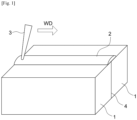
- Fig. 1 interfaces 4 of members of a steel material 1 are butted, a portion on the surfaces of the member of the steel material 1 including the weld line 4 is covered with flux 2, and a laser beam 3 is emitted from above to join the steel material members 1.
- the laser used herein need not be limited to a particular type, but welding is preferably performed with a fiber laser capable of high output while maintaining high beam quality.
- the welding conditions of the laser welding be appropriately selected in accordance with the thickness of the material to be welded.
- the thickness is 6 mm or more but less than 12 mm, it is preferable to set the laser output to 5 to 10 kW, and set the welding rate to 0.8 to 2.0 m/min.
- the thickness is 12 mm or more but less than 24 mm, it is preferable to set the laser output to 8 to 30 kW, and set the welding rate to 0.6 to 1.4 m/min.
- the thickness is 24 mm or more but less than 36 mm, it is preferable to set the laser output to 20 to 60 kW, and set the welding rate to 0.5 to 1.0 m/min.
- the thickness is in the range of 36 mm to 50 mm, it is preferable to set the laser output to 40 to 80 kW, and set the welding rate to 0.3 to 0.8 m/min.
- test sheets were prepared from each of the obtained steel materials.
- the lateral ends of the two test sheets were butted together, forming an I groove with a root gap of 0 mm therebetween.
- a portion of the surface of the steel material 1 including the weld line 4 was covered with the flux 2, and the laser beam 3 was emitted from above so that a laser weld joint was produced.
- the lateral end faces of the test sheets to be butted were subjected to cutting work.
- Table 3 shows the combination of the steel material and flux used to produce each joint. [Table 3] No. Steel Material No. Flux No.
- the laser welding was performed with a fiber laser under the following conditions: the laser output was set to 50 kW, the welding rate was set to 0.6 m/min, the defocus distance (distance inwards from the surface of the material to be joined) was set to -40 mm, the laser beam incidence angle was set to 10° (sweptback angle), and the height for spraying the flux was set to 10 mm.
- a cross-sectional microstructure was obtained from each of the obtained weld joints to examine the penetration depth as well as the presence or absence of cracks. Specifically, regarding the penetration depth, the length (mm) from the surface of the steel material to the position of the largest penetration of the weld metal along the cross-section of the weld joint was measured. Regarding the presence or absence of cracks, a case where a crack was observed in the cross-section of the weld metal was determined as "present,” while a case where no crack was observed was determined as "absent.”
- Chips were collected from a 1 mm diameter area 20 mm from the surface of the test sheet in the center of the weld metal. Then, elementary analysis based on wet analysis was conducted. Table 4 also shows the obtained results.
- V-notch Charpy impact test specimen
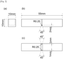
- a Charpy impact test specimen was collected from a position 20 mm from the surface of the test sheet of the weld joint in the center of the weld metal in the width direction. Then, a Charpy impact test was conducted at a test temperature of -20°C to determine the absorbed energy V E -20 (J). Note that a test specimen with side grooves shown in Fig. 2 was used as the V-notch Charpy impact test specimen herein to avoid a phenomenon of FPD (Fracture Path Deviation) in which a crack deviates to the base metal side. Table 4 shows the obtained results. [Table 4] No.
Landscapes
- Chemical & Material Sciences (AREA)
- Engineering & Computer Science (AREA)
- Mechanical Engineering (AREA)
- Materials Engineering (AREA)
- Metallurgy (AREA)
- Organic Chemistry (AREA)
- Physics & Mathematics (AREA)
- Optics & Photonics (AREA)
- Plasma & Fusion (AREA)
- Inorganic Chemistry (AREA)
- Nonmetallic Welding Materials (AREA)
- Laser Beam Processing (AREA)
Applications Claiming Priority (2)
| Application Number | Priority Date | Filing Date | Title |
|---|---|---|---|
| JP2022140559 | 2022-09-05 | ||
| PCT/JP2023/017290 WO2024053160A1 (ja) | 2022-09-05 | 2023-05-08 | レーザ溶接方法およびレーザ溶接継手 |
Publications (2)
| Publication Number | Publication Date |
|---|---|
| EP4560040A1 true EP4560040A1 (de) | 2025-05-28 |
| EP4560040A4 EP4560040A4 (de) | 2025-11-05 |
Family
ID=88729135
Family Applications (1)
| Application Number | Title | Priority Date | Filing Date |
|---|---|---|---|
| EP23862709.5A Pending EP4560040A4 (de) | 2022-09-05 | 2023-05-08 | Laserschweissverfahren und laserschweissverbindung |
Country Status (4)
| Country | Link |
|---|---|
| US (1) | US20260102854A1 (de) |
| EP (1) | EP4560040A4 (de) |
| JP (1) | JP7380959B1 (de) |
| CN (1) | CN119630505A (de) |
Family Cites Families (4)
| Publication number | Priority date | Publication date | Assignee | Title |
|---|---|---|---|---|
| JP4438210B2 (ja) * | 2000-10-18 | 2010-03-24 | Jfeスチール株式会社 | 鋼材のレーザ溶接継手およびレーザ溶接方法 |
| JP5953648B2 (ja) * | 2010-11-29 | 2016-07-20 | Jfeスチール株式会社 | 溶接金属部の靭性に優れた鋼材のレーザ溶接継手及び溶接金属部の靭性に優れた鋼材のレーザ溶接継手の製造方法 |
| JP2020082159A (ja) * | 2018-11-28 | 2020-06-04 | 株式会社ナ・デックス | レーザ溶接方法及びレーザ溶接用フラックス |
| JP2020147796A (ja) * | 2019-03-14 | 2020-09-17 | 日本製鉄株式会社 | Uoe鋼管用の溶接金属及びそれを溶接部に有するuoe鋼管 |
-
2023
- 2023-05-08 US US19/105,081 patent/US20260102854A1/en active Pending
- 2023-05-08 JP JP2023540905A patent/JP7380959B1/ja active Active
- 2023-05-08 CN CN202380059296.1A patent/CN119630505A/zh active Pending
- 2023-05-08 EP EP23862709.5A patent/EP4560040A4/de active Pending
Also Published As
| Publication number | Publication date |
|---|---|
| JPWO2024053160A1 (de) | 2024-03-14 |
| US20260102854A1 (en) | 2026-04-16 |
| CN119630505A (zh) | 2025-03-14 |
| KR20250040026A (ko) | 2025-03-21 |
| EP4560040A4 (de) | 2025-11-05 |
| JP7380959B1 (ja) | 2023-11-15 |
Similar Documents
| Publication | Publication Date | Title |
|---|---|---|
| EP1295672A1 (de) | Flussmittelkerndraht zum Lichtbogenschweissen in Schutzgas | |
| EP1995339B1 (de) | Stahlblech für pulverschweissen | |
| JP5387192B2 (ja) | ガスシールド溶接用フラックス入りワイヤ | |
| EP2674241A1 (de) | Schweissmetall mit ausgezeichneten kriecheigenschaften | |
| KR100508399B1 (ko) | 대입열 서브머지 아크용접 이음매, 그 이음매의 제조방법및 그것에 사용하는 용접용 강와이어 및 용접용 플럭스 | |
| US20240051070A1 (en) | Submerged arc welded joint | |
| EP2862953A1 (de) | Stahlmaterial mit hervorragender zähigkeit in von schweisshitze betroffenen zonen | |
| CN117177833B (zh) | 埋弧焊接头 | |
| JP4825057B2 (ja) | 溶接熱影響部の靭性に優れた鋼材およびその製法 | |
| WO2022230615A1 (ja) | サブマージアーク溶接継手 | |
| JP7594173B2 (ja) | 溶接継手の製造方法 | |
| EP4252959A1 (de) | Schweissverbindung und herstellungsverfahren dafür | |
| JP5320274B2 (ja) | 溶接熱影響部の靭性および強度の均一性に優れた厚鋼板 | |
| KR20030040067A (ko) | 대입열용접의 용접이음매 및 그 용접방법 | |
| TWI859928B (zh) | 雷射焊接方法及雷射焊接接頭 | |
| KR20130103399A (ko) | 가스 실드 아크 용접용 플럭스 코어드 와이어 | |
| US20260102854A1 (en) | Laser welding method and laser weld joint | |
| WO2018047880A1 (ja) | ガスシールドアーク溶接用フラックス入りワイヤ及び溶接金属 | |
| EP4365326A1 (de) | Unterpulverschweissverfahren | |
| JP3716980B2 (ja) | フェライト系ステンレス鋼の溶接構造物 | |
| TW202320955A (zh) | 雷射-電弧複合焊接接頭的製造方法 | |
| KR102963135B1 (ko) | 레이저 용접 방법 및 레이저 용접 조인트 | |
| JP7637710B2 (ja) | サブマージアーク溶接方法及び溶接継手の製造方法 | |
| EP4545243A1 (de) | Schweisselement und draht zum schutzgas-lichtbogenschweissen | |
| JP2002105590A (ja) | 高エネルギービーム溶接用鋼材 |
Legal Events
| Date | Code | Title | Description |
|---|---|---|---|
| STAA | Information on the status of an ep patent application or granted ep patent |
Free format text: STATUS: THE INTERNATIONAL PUBLICATION HAS BEEN MADE |
|
| PUAI | Public reference made under article 153(3) epc to a published international application that has entered the european phase |
Free format text: ORIGINAL CODE: 0009012 |
|
| STAA | Information on the status of an ep patent application or granted ep patent |
Free format text: STATUS: REQUEST FOR EXAMINATION WAS MADE |
|
| 17P | Request for examination filed |
Effective date: 20250219 |
|
| AK | Designated contracting states |
Kind code of ref document: A1 Designated state(s): AL AT BE BG CH CY CZ DE DK EE ES FI FR GB GR HR HU IE IS IT LI LT LU LV MC ME MK MT NL NO PL PT RO RS SE SI SK SM TR |
|
| REG | Reference to a national code |
Ref country code: DE Ref legal event code: R079 Free format text: PREVIOUS MAIN CLASS: C22C0038000000 Ipc: B23K0035360000 |
|
| A4 | Supplementary search report drawn up and despatched |
Effective date: 20251009 |
|
| RIC1 | Information provided on ipc code assigned before grant |
Ipc: B23K 35/36 20060101AFI20251002BHEP Ipc: B23K 26/00 20140101ALI20251002BHEP Ipc: B23K 26/24 20140101ALI20251002BHEP Ipc: B23K 26/21 20140101ALI20251002BHEP Ipc: B23K 35/362 20060101ALI20251002BHEP Ipc: C22C 38/02 20060101ALI20251002BHEP Ipc: C22C 38/00 20060101ALI20251002BHEP Ipc: C22C 38/04 20060101ALI20251002BHEP Ipc: C22C 38/08 20060101ALI20251002BHEP Ipc: C22C 38/12 20060101ALI20251002BHEP Ipc: C22C 38/14 20060101ALI20251002BHEP Ipc: C22C 38/16 20060101ALI20251002BHEP Ipc: C22C 38/22 20060101ALI20251002BHEP Ipc: C22C 38/28 20060101ALI20251002BHEP Ipc: C22C 38/32 20060101ALI20251002BHEP Ipc: C22C 38/38 20060101ALI20251002BHEP Ipc: C22C 38/54 20060101ALI20251002BHEP |
|
| DAV | Request for validation of the european patent (deleted) | ||
| DAX | Request for extension of the european patent (deleted) |