EP4560055A1 - Reaktor mit abnehmbarer reaktionseinheit - Google Patents
Reaktor mit abnehmbarer reaktionseinheit Download PDFInfo
- Publication number
- EP4560055A1 EP4560055A1 EP24214242.0A EP24214242A EP4560055A1 EP 4560055 A1 EP4560055 A1 EP 4560055A1 EP 24214242 A EP24214242 A EP 24214242A EP 4560055 A1 EP4560055 A1 EP 4560055A1
- Authority
- EP
- European Patent Office
- Prior art keywords
- reaction unit
- reaction
- susceptive
- casing
- chamber
- Prior art date
- Legal status (The legal status is an assumption and is not a legal conclusion. Google has not performed a legal analysis and makes no representation as to the accuracy of the status listed.)
- Pending
Links
Images




Classifications
-
- C—CHEMISTRY; METALLURGY
- C23—COATING METALLIC MATERIAL; COATING MATERIAL WITH METALLIC MATERIAL; CHEMICAL SURFACE TREATMENT; DIFFUSION TREATMENT OF METALLIC MATERIAL; COATING BY VACUUM EVAPORATION, BY SPUTTERING, BY ION IMPLANTATION OR BY CHEMICAL VAPOUR DEPOSITION, IN GENERAL; INHIBITING CORROSION OF METALLIC MATERIAL OR INCRUSTATION IN GENERAL
- C23C—COATING METALLIC MATERIAL; COATING MATERIAL WITH METALLIC MATERIAL; SURFACE TREATMENT OF METALLIC MATERIAL BY DIFFUSION INTO THE SURFACE, BY CHEMICAL CONVERSION OR SUBSTITUTION; COATING BY VACUUM EVAPORATION, BY SPUTTERING, BY ION IMPLANTATION OR BY CHEMICAL VAPOUR DEPOSITION, IN GENERAL
- C23C16/00—Chemical coating by decomposition of gaseous compounds, without leaving reaction products of surface material in the coating, i.e. chemical vapour deposition [CVD] processes
- C23C16/44—Chemical coating by decomposition of gaseous compounds, without leaving reaction products of surface material in the coating, i.e. chemical vapour deposition [CVD] processes characterised by the method of coating
- C23C16/4401—Means for minimising impurities, e.g. dust, moisture or residual gas, in the reaction chamber
-
- H—ELECTRICITY
- H10—SEMICONDUCTOR DEVICES; ELECTRIC SOLID-STATE DEVICES NOT OTHERWISE PROVIDED FOR
- H10P—GENERIC PROCESSES OR APPARATUS FOR THE MANUFACTURE OR TREATMENT OF DEVICES COVERED BY CLASS H10
- H10P72/00—Handling or holding of wafers, substrates or devices during manufacture or treatment thereof
- H10P72/30—Handling or holding of wafers, substrates or devices during manufacture or treatment thereof for conveying, e.g. between different workstations
- H10P72/34—Handling or holding of wafers, substrates or devices during manufacture or treatment thereof for conveying, e.g. between different workstations the wafers being stored in a carrier, involving loading and unloading
- H10P72/3402—Mechanical parts of transfer devices
-
- C—CHEMISTRY; METALLURGY
- C23—COATING METALLIC MATERIAL; COATING MATERIAL WITH METALLIC MATERIAL; CHEMICAL SURFACE TREATMENT; DIFFUSION TREATMENT OF METALLIC MATERIAL; COATING BY VACUUM EVAPORATION, BY SPUTTERING, BY ION IMPLANTATION OR BY CHEMICAL VAPOUR DEPOSITION, IN GENERAL; INHIBITING CORROSION OF METALLIC MATERIAL OR INCRUSTATION IN GENERAL
- C23C—COATING METALLIC MATERIAL; COATING MATERIAL WITH METALLIC MATERIAL; SURFACE TREATMENT OF METALLIC MATERIAL BY DIFFUSION INTO THE SURFACE, BY CHEMICAL CONVERSION OR SUBSTITUTION; COATING BY VACUUM EVAPORATION, BY SPUTTERING, BY ION IMPLANTATION OR BY CHEMICAL VAPOUR DEPOSITION, IN GENERAL
- C23C16/00—Chemical coating by decomposition of gaseous compounds, without leaving reaction products of surface material in the coating, i.e. chemical vapour deposition [CVD] processes
- C23C16/44—Chemical coating by decomposition of gaseous compounds, without leaving reaction products of surface material in the coating, i.e. chemical vapour deposition [CVD] processes characterised by the method of coating
-
- C—CHEMISTRY; METALLURGY
- C23—COATING METALLIC MATERIAL; COATING MATERIAL WITH METALLIC MATERIAL; CHEMICAL SURFACE TREATMENT; DIFFUSION TREATMENT OF METALLIC MATERIAL; COATING BY VACUUM EVAPORATION, BY SPUTTERING, BY ION IMPLANTATION OR BY CHEMICAL VAPOUR DEPOSITION, IN GENERAL; INHIBITING CORROSION OF METALLIC MATERIAL OR INCRUSTATION IN GENERAL
- C23C—COATING METALLIC MATERIAL; COATING MATERIAL WITH METALLIC MATERIAL; SURFACE TREATMENT OF METALLIC MATERIAL BY DIFFUSION INTO THE SURFACE, BY CHEMICAL CONVERSION OR SUBSTITUTION; COATING BY VACUUM EVAPORATION, BY SPUTTERING, BY ION IMPLANTATION OR BY CHEMICAL VAPOUR DEPOSITION, IN GENERAL
- C23C16/00—Chemical coating by decomposition of gaseous compounds, without leaving reaction products of surface material in the coating, i.e. chemical vapour deposition [CVD] processes
- C23C16/44—Chemical coating by decomposition of gaseous compounds, without leaving reaction products of surface material in the coating, i.e. chemical vapour deposition [CVD] processes characterised by the method of coating
- C23C16/52—Controlling or regulating the coating process
-
- C—CHEMISTRY; METALLURGY
- C23—COATING METALLIC MATERIAL; COATING MATERIAL WITH METALLIC MATERIAL; CHEMICAL SURFACE TREATMENT; DIFFUSION TREATMENT OF METALLIC MATERIAL; COATING BY VACUUM EVAPORATION, BY SPUTTERING, BY ION IMPLANTATION OR BY CHEMICAL VAPOUR DEPOSITION, IN GENERAL; INHIBITING CORROSION OF METALLIC MATERIAL OR INCRUSTATION IN GENERAL
- C23C—COATING METALLIC MATERIAL; COATING MATERIAL WITH METALLIC MATERIAL; SURFACE TREATMENT OF METALLIC MATERIAL BY DIFFUSION INTO THE SURFACE, BY CHEMICAL CONVERSION OR SUBSTITUTION; COATING BY VACUUM EVAPORATION, BY SPUTTERING, BY ION IMPLANTATION OR BY CHEMICAL VAPOUR DEPOSITION, IN GENERAL
- C23C16/00—Chemical coating by decomposition of gaseous compounds, without leaving reaction products of surface material in the coating, i.e. chemical vapour deposition [CVD] processes
- C23C16/44—Chemical coating by decomposition of gaseous compounds, without leaving reaction products of surface material in the coating, i.e. chemical vapour deposition [CVD] processes characterised by the method of coating
- C23C16/54—Apparatus specially adapted for continuous coating
-
- C—CHEMISTRY; METALLURGY
- C30—CRYSTAL GROWTH
- C30B—SINGLE-CRYSTAL GROWTH; UNIDIRECTIONAL SOLIDIFICATION OF EUTECTIC MATERIAL OR UNIDIRECTIONAL DEMIXING OF EUTECTOID MATERIAL; REFINING BY ZONE-MELTING OF MATERIAL; PRODUCTION OF A HOMOGENEOUS POLYCRYSTALLINE MATERIAL WITH DEFINED STRUCTURE; SINGLE CRYSTALS OR HOMOGENEOUS POLYCRYSTALLINE MATERIAL WITH DEFINED STRUCTURE; AFTER-TREATMENT OF SINGLE CRYSTALS OR A HOMOGENEOUS POLYCRYSTALLINE MATERIAL WITH DEFINED STRUCTURE; APPARATUS THEREFOR
- C30B25/00—Single-crystal growth by chemical reaction of reactive gases, e.g. chemical vapour-deposition growth
- C30B25/02—Epitaxial-layer growth
-
- C—CHEMISTRY; METALLURGY
- C30—CRYSTAL GROWTH
- C30B—SINGLE-CRYSTAL GROWTH; UNIDIRECTIONAL SOLIDIFICATION OF EUTECTIC MATERIAL OR UNIDIRECTIONAL DEMIXING OF EUTECTOID MATERIAL; REFINING BY ZONE-MELTING OF MATERIAL; PRODUCTION OF A HOMOGENEOUS POLYCRYSTALLINE MATERIAL WITH DEFINED STRUCTURE; SINGLE CRYSTALS OR HOMOGENEOUS POLYCRYSTALLINE MATERIAL WITH DEFINED STRUCTURE; AFTER-TREATMENT OF SINGLE CRYSTALS OR A HOMOGENEOUS POLYCRYSTALLINE MATERIAL WITH DEFINED STRUCTURE; APPARATUS THEREFOR
- C30B25/00—Single-crystal growth by chemical reaction of reactive gases, e.g. chemical vapour-deposition growth
- C30B25/02—Epitaxial-layer growth
- C30B25/08—Reaction chambers; Selection of materials therefor
-
- C—CHEMISTRY; METALLURGY
- C30—CRYSTAL GROWTH
- C30B—SINGLE-CRYSTAL GROWTH; UNIDIRECTIONAL SOLIDIFICATION OF EUTECTIC MATERIAL OR UNIDIRECTIONAL DEMIXING OF EUTECTOID MATERIAL; REFINING BY ZONE-MELTING OF MATERIAL; PRODUCTION OF A HOMOGENEOUS POLYCRYSTALLINE MATERIAL WITH DEFINED STRUCTURE; SINGLE CRYSTALS OR HOMOGENEOUS POLYCRYSTALLINE MATERIAL WITH DEFINED STRUCTURE; AFTER-TREATMENT OF SINGLE CRYSTALS OR A HOMOGENEOUS POLYCRYSTALLINE MATERIAL WITH DEFINED STRUCTURE; APPARATUS THEREFOR
- C30B25/00—Single-crystal growth by chemical reaction of reactive gases, e.g. chemical vapour-deposition growth
- C30B25/02—Epitaxial-layer growth
- C30B25/12—Substrate holders or susceptors
-
- C—CHEMISTRY; METALLURGY
- C30—CRYSTAL GROWTH
- C30B—SINGLE-CRYSTAL GROWTH; UNIDIRECTIONAL SOLIDIFICATION OF EUTECTIC MATERIAL OR UNIDIRECTIONAL DEMIXING OF EUTECTOID MATERIAL; REFINING BY ZONE-MELTING OF MATERIAL; PRODUCTION OF A HOMOGENEOUS POLYCRYSTALLINE MATERIAL WITH DEFINED STRUCTURE; SINGLE CRYSTALS OR HOMOGENEOUS POLYCRYSTALLINE MATERIAL WITH DEFINED STRUCTURE; AFTER-TREATMENT OF SINGLE CRYSTALS OR A HOMOGENEOUS POLYCRYSTALLINE MATERIAL WITH DEFINED STRUCTURE; APPARATUS THEREFOR
- C30B25/00—Single-crystal growth by chemical reaction of reactive gases, e.g. chemical vapour-deposition growth
- C30B25/02—Epitaxial-layer growth
- C30B25/14—Feed and outlet means for the gases; Modifying the flow of the reactive gases
-
- C—CHEMISTRY; METALLURGY
- C30—CRYSTAL GROWTH
- C30B—SINGLE-CRYSTAL GROWTH; UNIDIRECTIONAL SOLIDIFICATION OF EUTECTIC MATERIAL OR UNIDIRECTIONAL DEMIXING OF EUTECTOID MATERIAL; REFINING BY ZONE-MELTING OF MATERIAL; PRODUCTION OF A HOMOGENEOUS POLYCRYSTALLINE MATERIAL WITH DEFINED STRUCTURE; SINGLE CRYSTALS OR HOMOGENEOUS POLYCRYSTALLINE MATERIAL WITH DEFINED STRUCTURE; AFTER-TREATMENT OF SINGLE CRYSTALS OR A HOMOGENEOUS POLYCRYSTALLINE MATERIAL WITH DEFINED STRUCTURE; APPARATUS THEREFOR
- C30B25/00—Single-crystal growth by chemical reaction of reactive gases, e.g. chemical vapour-deposition growth
- C30B25/02—Epitaxial-layer growth
- C30B25/16—Controlling or regulating
-
- C—CHEMISTRY; METALLURGY
- C30—CRYSTAL GROWTH
- C30B—SINGLE-CRYSTAL GROWTH; UNIDIRECTIONAL SOLIDIFICATION OF EUTECTIC MATERIAL OR UNIDIRECTIONAL DEMIXING OF EUTECTOID MATERIAL; REFINING BY ZONE-MELTING OF MATERIAL; PRODUCTION OF A HOMOGENEOUS POLYCRYSTALLINE MATERIAL WITH DEFINED STRUCTURE; SINGLE CRYSTALS OR HOMOGENEOUS POLYCRYSTALLINE MATERIAL WITH DEFINED STRUCTURE; AFTER-TREATMENT OF SINGLE CRYSTALS OR A HOMOGENEOUS POLYCRYSTALLINE MATERIAL WITH DEFINED STRUCTURE; APPARATUS THEREFOR
- C30B29/00—Single crystals or homogeneous polycrystalline material with defined structure characterised by the material or by their shape
- C30B29/10—Inorganic compounds or compositions
- C30B29/36—Carbides
-
- C—CHEMISTRY; METALLURGY
- C30—CRYSTAL GROWTH
- C30B—SINGLE-CRYSTAL GROWTH; UNIDIRECTIONAL SOLIDIFICATION OF EUTECTIC MATERIAL OR UNIDIRECTIONAL DEMIXING OF EUTECTOID MATERIAL; REFINING BY ZONE-MELTING OF MATERIAL; PRODUCTION OF A HOMOGENEOUS POLYCRYSTALLINE MATERIAL WITH DEFINED STRUCTURE; SINGLE CRYSTALS OR HOMOGENEOUS POLYCRYSTALLINE MATERIAL WITH DEFINED STRUCTURE; AFTER-TREATMENT OF SINGLE CRYSTALS OR A HOMOGENEOUS POLYCRYSTALLINE MATERIAL WITH DEFINED STRUCTURE; APPARATUS THEREFOR
- C30B29/00—Single crystals or homogeneous polycrystalline material with defined structure characterised by the material or by their shape
- C30B29/10—Inorganic compounds or compositions
- C30B29/40—AIIIBV compounds wherein A is B, Al, Ga, In or Tl and B is N, P, As, Sb or Bi
- C30B29/403—AIII-nitrides
- C30B29/406—Gallium nitride
-
- C—CHEMISTRY; METALLURGY
- C30—CRYSTAL GROWTH
- C30B—SINGLE-CRYSTAL GROWTH; UNIDIRECTIONAL SOLIDIFICATION OF EUTECTIC MATERIAL OR UNIDIRECTIONAL DEMIXING OF EUTECTOID MATERIAL; REFINING BY ZONE-MELTING OF MATERIAL; PRODUCTION OF A HOMOGENEOUS POLYCRYSTALLINE MATERIAL WITH DEFINED STRUCTURE; SINGLE CRYSTALS OR HOMOGENEOUS POLYCRYSTALLINE MATERIAL WITH DEFINED STRUCTURE; AFTER-TREATMENT OF SINGLE CRYSTALS OR A HOMOGENEOUS POLYCRYSTALLINE MATERIAL WITH DEFINED STRUCTURE; APPARATUS THEREFOR
- C30B35/00—Apparatus not otherwise provided for, specially adapted for the growth, production or after-treatment of single crystals or of a homogeneous polycrystalline material with defined structure
- C30B35/005—Transport systems
-
- H—ELECTRICITY
- H10—SEMICONDUCTOR DEVICES; ELECTRIC SOLID-STATE DEVICES NOT OTHERWISE PROVIDED FOR
- H10P—GENERIC PROCESSES OR APPARATUS FOR THE MANUFACTURE OR TREATMENT OF DEVICES COVERED BY CLASS H10
- H10P72/00—Handling or holding of wafers, substrates or devices during manufacture or treatment thereof
- H10P72/04—Apparatus for manufacture or treatment
- H10P72/0402—Apparatus for fluid treatment
-
- H—ELECTRICITY
- H10—SEMICONDUCTOR DEVICES; ELECTRIC SOLID-STATE DEVICES NOT OTHERWISE PROVIDED FOR
- H10P—GENERIC PROCESSES OR APPARATUS FOR THE MANUFACTURE OR TREATMENT OF DEVICES COVERED BY CLASS H10
- H10P72/00—Handling or holding of wafers, substrates or devices during manufacture or treatment thereof
- H10P72/04—Apparatus for manufacture or treatment
- H10P72/0451—Apparatus for manufacturing or treating in a plurality of work-stations
- H10P72/0462—Apparatus for manufacturing or treating in a plurality of work-stations characterised by the construction of the processing chambers, e.g. modular processing chambers
-
- H—ELECTRICITY
- H10—SEMICONDUCTOR DEVICES; ELECTRIC SOLID-STATE DEVICES NOT OTHERWISE PROVIDED FOR
- H10P—GENERIC PROCESSES OR APPARATUS FOR THE MANUFACTURE OR TREATMENT OF DEVICES COVERED BY CLASS H10
- H10P72/00—Handling or holding of wafers, substrates or devices during manufacture or treatment thereof
- H10P72/30—Handling or holding of wafers, substrates or devices during manufacture or treatment thereof for conveying, e.g. between different workstations
- H10P72/33—Handling or holding of wafers, substrates or devices during manufacture or treatment thereof for conveying, e.g. between different workstations into and out of processing chamber
- H10P72/3302—Mechanical parts of transfer devices
-
- H—ELECTRICITY
- H10—SEMICONDUCTOR DEVICES; ELECTRIC SOLID-STATE DEVICES NOT OTHERWISE PROVIDED FOR
- H10P—GENERIC PROCESSES OR APPARATUS FOR THE MANUFACTURE OR TREATMENT OF DEVICES COVERED BY CLASS H10
- H10P72/00—Handling or holding of wafers, substrates or devices during manufacture or treatment thereof
- H10P72/30—Handling or holding of wafers, substrates or devices during manufacture or treatment thereof for conveying, e.g. between different workstations
- H10P72/33—Handling or holding of wafers, substrates or devices during manufacture or treatment thereof for conveying, e.g. between different workstations into and out of processing chamber
- H10P72/3306—Horizontal transfer of a single workpiece
Definitions
- the present invention relates to the field of epitaxial deposition of semiconductor films on substrates; in particular to a reaction chamber featuring a removable reaction unit and a reactor incorporating said reaction chamber.
- the present invention further relates to an assembly and method adapted to reduce preventive maintenance times of the reactor.
- the present invention relates to the field of the deposition of silicon carbide and gallium nitride films on a semiconductor substrate in a hot-wall, crossflow, homoepitaxial or heteroepitaxial reactor.
- Semiconductor films made by epitaxial growth are formed by deposition in the reaction chamber of a reactor.
- the deposited material may be the same as the substrate or involve different semiconductors with specific desirable qualities.
- Epitaxial techniques allow to control the crystal structure formed over the substrate and to improve the epilayer surface's features, making them suitable for the manufacturing of highly complex microprocessors and memory devices.
- the reaction chamber is heated to a desired temperature before film deposition, and then the temperature is maintained substantially constant throughout the deposition process.
- insulating systems are used to reduce the energy required to achieve and maintain the nominal temperature of the deposition process.
- the epitaxial growth equipment for the SiC industry usually comprises a reactor containing a reaction and deposition chamber where the chemical vapor deposition process occurs.
- a reaction and deposition chamber where the chemical vapor deposition process occurs.
- several parts of the chamber will be subject to undesired product build-up and will require cleaning or substitution after reaching a certain thickness, to avoid affecting the quality and performance of the reaction and deposition process.
- the reactor is of the removable type
- the process still presents the disadvantages described above: the access to the chamber is not fully automated or automatable, the reactor is exposed to air, and its displacement (and handling) is cumbersome. Above all, the downtime is still disadvantageously long, as it takes at least eight hours for all necessary operations to be completed and requires the presence of an operator.
- Said reaction chamber, reactor, assembly, and method allow avoiding exposure of the reaction chamber to air, while providing the optional opportunity to handle the removable reaction unit with a completely automated system.
- Epitaxial reactors of cylindrical shape such as those described in EP 1570107 and US2022411961 , have proven commercially successful thanks to the uniformity and efficiency of the heating of the reaction chamber, the simplicity of construction, and the quality of the deposited films.
- SiC and GaN epitaxial film deposition they may operate at temperatures between 1000-1800 °C.
- These cylindrical reactors typically extend rather uniformly along a longitudinal horizontal direction and exhibit an essentially circular cross section.
- a reaction chamber formed by one or more structural elements.
- Two of these structural elements may exhibit high susceptivity, for instance they can be made of graphite and exhibit a half-moon shape. They may be heated via induction means, such as one or more induction coils wrapped around the reactor.
- Other structural elements of the reaction chamber may be made of a same of a different material, such as SiC, to impart preferential current flows in the susceptive elements and expedite their induction heating.
- susceptive element here and in the following, it is meant an element made of a material with high susceptivity, i.e., which can be heated efficiently by induction.
- the reaction chamber described in EP 1570107 and US2022411961 is formed via the assembly of the pieces above described.
- the assembly creates an inner space, of essentially parallelepiped shape, where the actual reaction takes place.
- This simple parallelepiped shape cannot be separated and moved in one piece from the constituting susceptive elements; overall the chamber exhibits a complex profile of substantially circular cross section and intersecting lines, as it is the result of the combination of all the elements described above.
- the above reaction chamber is typically surrounded by an upper and a lower casing made of a thermally insulating material.
- porous carbonaceous materials can be used, for instance carbon composites made from short cut carbon fibers, optionally interconnected in a matrix or pressed together.
- the above cylindrical reactors may be surrounded by an enclosure, which may be made of quartz or other material that is relatively transparent to induction heating and that is resistant to high temperature.
- This enclosure may exhibit a double wall and can be cooled with a cooling fluid such as water flowing in the interspace between its two walls. This allows the enclosure to maintain its structural properties even when exposed to high temperatures.
- the present invention relates to a reaction chamber for the epitaxial deposition of a semiconductor film on a substrate, comprising:
- one or more walls of the at least four walls are either integral to each other (for example, they may be manufactured in one piece), or joined together via permanent or releasable means (for example, they may be permanently joined via welding, or releasably connected with mechanical interlocking systems, rivets or screws).
- the removable reaction unit may have a box-like shape, with the four walls essentially parallel to the longitudinal direction. However, they may also slightly converge towards the upstream or downstream side.
- the cross section of each wall in the transverse plane may present a straight profile or be curved or bent.
- the reaction chamber may exhibit an ovaloid shape.
- One of the four walls of the reaction unit is a bottom wall provided with a receiving area adapted to receive a substrate holder.
- the sides of the reaction unit (upstream or downstream) can be completely open or feature an upstream and/or downstream wall.
- the upstream side comprises an upstream aperture suited to receive a flow of carrier and precursor gases for the epitaxial deposition.
- the downstream side comprises a downstream aperture suited to discharge a flow of exhaust gases.
- the apertures can take up the entire upstream/downstream sides or be holes traversing the corresponding upstream and/or downstream walls.
- the reaction unit according to the invention is mechanically connected to the susceptive casing via releasable coupling means, which can be used to support and/or fasten and/or align the reaction unit with/to the susceptive casing.
- the reaction unit and the releasable coupling means are adapted to withdraw or insert the reaction unit from or into the susceptive casing in one piece.
- the susceptive casing is adapted to be heated by induction, and to this effect it can be advantageously made in graphite.
- the reaction unit is principally heated by the by susceptive casing through irradiation from the susceptive casing.
- the susceptive casing may exhibit a hollow prismatic or cylindrical shape with a polygonal, circular, oval or elliptical cross-section in the transverse plane.
- An essentially circular cross section may allow an advantageously uniform heat distribution.
- the susceptive casing may be advantageously open on one or both sides in the transverse plane (yz) to facilitate access to the reaction unit.
- the opening may be advantageously closed with insulating lids during operation.
- the susceptive casing may exhibit a variable thickness either in the longitudinal direction (x) and/or in the transverse plane (yz), as discussed in Fig. 5 , Fig. 6, and Fig. 7 .
- the four walls of the reaction unit comprise a top wall and two lateral walls.
- Either the top wall or the bottom wall can be beneficially connected to the two lateral walls and to the upstream and downstream sides via releasable coupling means.
- This embodiment allows to easily access the internal parts of the chamber (the disposable graphite parts and/or the inner surfaces of the walls) for maintenance and/or replacement.
- the releasable coupling means are non-permanent mechanical interlocking or fastening mechanisms, such as hook and loop mechanisms, snap closures, or any other female-male fastening/joining means suitable to be quickly and easily released.
- the internal surface of the susceptive casing is provided with grooves or protrusions adapted to support, position, and/or releasably fasten the reaction unit onto it.
- the reaction unit may also be advantageously provided with protrusions or grooves on its outer surface adapted to releasably engage with the grooves or protrusions of the internal surface of the susceptive casing through non-permanent mechanical interlocking or fastening mechanisms.
- Such mechanisms include, among others, any joints with releasable, i.e. non-permanent, interlocking shapes, such as any mechanism where a protruding part is adapted to latch on a corresponding indentation or hoop, and include hook and loop mechanisms, snap closures, etc.
- top wall and bottom wall of the reaction unit of the present invention are made of graphite, while the lateral walls, and/or the upstream and downstream sides in case they are only partially open, are made of graphite or silicon carbide.
- every wall of the reaction chamber can be made of graphite, but the inner surface of the reaction unit may be covered or coated, in toto or in part, with SiC, TaC or other materials, to protect graphite parts during deposition or during cleaning operations.
- the reaction unit further comprises a removable cover of a thermally insulating material situated over the downstream aperture and provided with at least one opening aligned in toto or in part with the downstream aperture and suitable to discharge a flow of exhaust gases.
- the cover's opening and the downstream aperture may be optionally additionally adapted to allow the insertion and withdrawal of a substrate holder.
- the removable cover may be further coupled to at least one of the four walls via releasable fastening means.
- the reaction unit may further comprise an upstream thermal insulation element, optionally detachable, positioned on the top and/or bottom wall at a distance ⁇ 20% L from the upstream side; where L is the minimum distance between the downstream side and the upstream side in the longitudinal direction.
- an upstream thermal insulation element optionally detachable
- the thermally insulating materials used in the above embodiments may be carbonaceous, preferably porous, materials.
- carbon composites made from short cut carbon fibers, optionally interconnected in a matrix or pressed together, may be advantageously chosen.
- the surface of these materials may be coated to improve their compactness and reduce the risk of debris created by detaching of fibers or other pieces.
- the reaction unit further comprises a first transition piece, optionally detachable, positioned over the upstream aperture adapted to be coupled with a precursor gas liner.
- reaction unit of the reaction chamber according to the invention may further comprise engaging means, such as indentation, protrusions, hooks, loops, or slides, adapted to mechanically couple with an end effector of an automated handling machine, in order to be withdrawn/inserted from/into the susceptive casing in one piece in an automated fashion. This allows to upgrade the removal of the reactor unit from manual to automated means.
- the reaction unit according to the present invention is compact and adapted to be handled. For instance, it may measure 200 - 400 mm times 30 - 50 mm in the transverse plane, and 200 - 500 mm in the longitudinal direction.
- the reaction unit may typically weight between 2-10 kg, preferably 2,5-6 kg.
- the susceptive casing may measure 200 - 500 mm in the longitudinal direction, and have a diameter, and/or its major length in the transverse direction of 210 - 450 mm.
- the reaction unit may be equipped with a plurality of inner coverings adapted to be secured around the receiving area, to control the exposure of the substrate holder to the flow of precursor gases, and/or to protect the exposed bottom surface of the reaction unit from parasitic build-up.
- inner coverings may be easily collected from the reaction unit during preventive maintenance for cleaning or replacement.
- These inner coverings are made of graphite and coated with SiC and/or TaC.
- the present invention relates to a Reactor suitable for the epitaxial deposition of a semiconductor film on a substrate, comprising: (i) at least one reaction chamber according to any of the embodiments hereinbefore described; (ii) a thermal insulation system, comprising one or more thermally insulating components, enclosing the reaction chamber; (iii) a liner suitable to direct process gases in the reaction unit and connected to the reaction unit with releasable coupling means.
- the reactor may advantageously comprise 1 - 8 reaction chambers, preferably 2-6 reaction chambers.
- the liner may comprise a (second) transition piece that may be coupled to the first transition piece attached to the upstream side of the reaction unit.
- the one or more thermally insulating components should be made of a rigid material suitable to withstand the high temperatures reached by the reactor.
- they can be made of rigid carbonaceous materials (such as materials comprising short cut carbon fibers, optionally interconnected in a matrix or pressed together).
- All surfaces of the thermally insulating components may be advantageously coated to improve their compactness and reduce the formation of debris, as may result from the detachment of fibers or other particles from the bulk insulating material.
- the coating used may be a graphite-based coating.
- the reactor may also advantageously include an outer enclosure, such a double wall quartz tube, suitable to have a cooling fluid flow in the interspace between its two walls.
- an outer enclosure such as a double wall quartz tube
- Other elements which are typically used in reactors such as those hereinbefore described, can be present, as it is apparent to a person with average skill in the art.
- One or more induction coils and or capacitors may be located outside the reactor in order to heat the susceptive casing and, directly or indirectly, the reaction unit of each reaction chamber.
- the present invention relates to an assembly for displacing and handling a reaction unit for preventive reactor maintenance operations.
- the assembly comprises the reactor hereinbefore described; a transfer chamber and a unit handling chamber.
- the transfer chamber features a first aperture provided with a first gate valve adapted to receive or discharge the reaction unit from/to the reactor via one or more automated machines or via manual means; and a second aperture provided with a second gate valve.
- the unit handling chamber is placed in communication with the transfer chamber through the second aperture and the second gate valve and is adapted to receive or discharge the reaction unit from/to the transfer chamber via motorized mechanical means.
- the unit handling chamber is adapted to condition the reaction unit and is provided with a resealable access, such as a door, hatch, porthole, or valve, suitable for the extraction and insertion of the reaction unit by an operator or by automated handling means.
- a resealable access such as a door, hatch, porthole, or valve, suitable for the extraction and insertion of the reaction unit by an operator or by automated handling means.
- conditioning it is meant a variety of operations, or cycles, suitable to prepare a reaction unit before insertion in the reactor.
- the operations or cycles are adapted to make the reaction unit suitable to be accessed by an operator or machine and extracted from the assembly for the removal or cleaning of its parts.
- a possible cycle may comprise the step of creating a vacuum of less than 10 mbar, and to perform a refilling under an inert gas such as argon, nitrogen, helium, or xenon.
- the reaction unit may undergo an inert gas purge, the inert gas of preference being argon.
- An alternative cycle suited to be performed on a new/clean reaction unit before insertion in the reactor may comprise the steps of heating and vacuum degassing (the vacuum in this case should preferably be below 1 mbar, even more preferably below 10 -3 mbar).
- the transfer chamber may be advantageously adapted to also receive or discharge through the first aperture a substrate holder from/to the reactor via motorized mechanical means.
- the assembly according to this embodiment may optionally and advantageously comprise a load lock chamber placed in communication with the transfer chamber through a third aperture and a third gate valve.
- the load lock chamber can therefore receive or discharge the substrate holder from/to the transfer chamber via motorized mechanical means through the third aperture.
- the load lock chamber may additionally comprise a resealable access suitable for the extraction and insertion of the substrate holder by an operator or by automated handling means.
- the assembly according to the invention further comprises a first automated handling machine provided with a first end effector.
- the latter is suitable to engage the reaction unit to withdraw it from the susceptive casing and insert it in the transfer chamber, and vice versa.
- the first end effector may be advantageously adapted to couple with the reactor unit through the engaging means present on the latter, if present.
- the first automated handling machine may be also optionally provided with a second end effector suitable to engage with a substrate holder to insert or withdraw it to/from the reaction unit.
- the present invention relates to a method for preventive maintenance of the reaction unit of the reactor previously disclosed, and comprising the following steps:
- step (c) may be executed according to the following sub-steps:
- reaction chamber design of the present invention it is therefore possible with the reaction chamber design of the present invention, to make a reactor, and an assembly adapted to easily access the reaction unit for preventive maintenance operations, allowing to remove it or insert it from/in the susceptive casing and the reactor via manual or automated means, and perform conditioning operations prior to cleaning without exposing the chamber to air and ensuring secure working conditions for the operators who subsequently handle said unit. This process allows to reduce preventive maintenance times of 70%.
- the possible automation of the process and the specific use of connected chambers makes it possible to avoid the concurrent presence of an operator during the displacement of the reaction unit within the reactor and/or the assembly.
- the present invention relates to the use of the reactor hereinbefore described for a hot-wall, crossflow, epitaxial deposition of silicon carbide or gallium nitride.
- Fig. 1 schematically depicts a cross section in the transverse plane (yz) of an embodiment of the reaction chamber (100) of the present invention.
- the reaction chamber is suited for the epitaxial deposition of a semiconductor film on a substrate and comprises a hollow susceptive casing (200) and a reaction unit (300).
- the susceptive casing extends along a longitudinal direction (x), perpendicular to the transverse plane.
- the susceptive casing features an internal surface (250) and an external surface, and contains the removable reaction unit (300).
- the reaction unit (300) has a box-like shape. It comprises four walls (310, 320, 330, 340) extending along the longitudinal direction.
- the four walls include a top wall (320), two lateral walls (330, 340) and a bottom wall (310).
- the latter is provided with a receiving area (311) adapted to receive a substrate holder (315).
- the reaction unit further comprises an upstream side (not shown) and a downstream side (360) parallel to a transverse plane (yz).
- the downstream side is a wall provided with a downstream aperture (361) suited to receive a flow of carrier and precursor gases for the epitaxial deposition.
- the upstream side is completely open and corresponds to the upstream aperture indicate by a dashed line (351).
- the upstream aperture is suited to discharge a flow of exhaust gases.
- the reaction unit is mechanically connected to the susceptive casing via releasable coupling means (331, 332). It can be moveable relative to the susceptive casing in one piece, thereby facilitating its insertion and withdrawal from/to the susceptive casing, and reducing the time required for preventive maintenance operations.
- the top wall (320) is connected to the two lateral walls and to the upstream and downstream sides via releasable coupling means (321), such as female-male interlocking mechanisms.
- the handling of the reaction unit can be facilitated and automated by providing it with engaging means, such as indentations (371, 372), adapted to couple with an end effector of an automated handling machine.
- the end effector may have a fork-like shape provided with two prongs adapted to couple with the indentations (371, 372).
- Fig. 2 illustrates a schematic isometric view of the susceptive casing (panel I) and the reaction unit (panel II) of the reaction chamber (100) of Fig. 1 .
- Fig. 2 panel I, shows a susceptive casing (200) having a hollow cylindrical shape and extending along a longitudinal direction (x), perpendicular to the transverse plane (yz).
- the susceptive casing features an internal surface (250) and an external surface and is adapted to contain the removable reaction unit (300) of panel II.
- the susceptive casing is provided with protrusions (251, 252) extending from its internal surface and adapted to support and position the reaction unit onto said surface.
- the reaction unit may slide onto these protrusions in and out from the susceptive casing.
- grooves (253, 254) can be used. These can be shaped to engage with corresponding protrusions on the outer surface of the reaction unit, such as the protrusions (331, 332) depicted in Fig. 2 , panel II, to create an interlocking system.
- Fig. 2 panel II, shows the reaction unit (300) of Fig. 1 , with the open upstream side (350) and corresponding aperture (351) more clearly visible.
- Fig. 3 provides an isometric, schematic view, of the reaction unit depicted in Fig. 2 , panel II, according to a second embodiment.
- the reaction unit is further equipped with a removable cover (400) of a thermally insulating material situated over the downstream side (360) and provided with one opening (401). This opening is aligned with the downstream aperture (361) and is suitable to discharge a flow of exhaust gases.
- the reaction unit also comprises a first transition piece (500) positioned over the upstream aperture (351) and adapted to be coupled with a precursor gas liner.
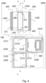
- Fig. 4 shows a simplified schematic view an assembly (2000) according to an embodiment of the invention.
- the assembly is designed to facilitate the displacement and handling of a reaction unit, such as, but not limited to the ones illustrated in Fig. 1-3 , for preventive reactor maintenance operations.
- the assembly comprises a reactor (1000) coupled to a system of connected chambers (2100, 2200, 2300).
- the reactor comprises a double wall quartz tube and is wrapped by an induction coil for heating (not shown).
- the reactor further comprises a thermal insulation system (1100) wrapped around the reaction chamber.
- the latter includes a susceptive casing (200) and a reaction unit (300).
- the reaction unit features a first transition piece (500) positioned over the upstream aperture (351) and coupled to a liner (1200).
- the reaction unit further comprises a removable cover (400) of a thermally insulating material situated over the downstream side (360) and provided with one opening (401) aligned with the downstream aperture (361).
- the reaction unit is equipped with engaging means (371, 372), adapted to couple with an end effector of an automated handling machine (not shown).
- the reactor can be connected to the system of connected chambers (2100, 2200, 2300) via a downstream drum (700).
- the system of chambers comprises a transfer chamber (2100) having a first aperture (2110) provided with a first gate valve (2111) and adapted to receive or discharge the reaction unit from/to the reactor through the downstream drum via one or more automated machines (or, less preferably, via manual means).
- the transfer chamber also features a second aperture (2120) provided with a second gate valve (2121).
- the system of connected chambers (2100, 2200, 2300) also comprises a unit handling chamber (2200) placed in communication with the transfer chamber through the second aperture (2120) and the second gate valve (2121).
- the unit handling chamber is adapted to receive or discharge the reaction unit from/to the transfer chamber via motorized mechanical means and is provided with a resealable access (2210) suitable for the extraction and insertion of the reaction unit (300) by an operator or by automated handling means.
- the unit handling chamber may be used to condition the reaction unit, before its withdrawal from the assembly, or prior to its insertion in the reactor through the transfer chamber.
- the system of connected chambers (2100, 2200, 2300) also comprises a load lock chamber (2300) placed in communication with the transfer chamber through a third aperture (2130) and a third gate valve (2131).
- the load lock chamber is adapted to receive or discharge the substrate holder from/to the transfer chamber through the third aperture, via motorized mechanical means (not shown).
- the assembly according to the present embodiment may be equipped with a first automated handling machine (not shown) provided with a first end effector suitable to engage with the reaction unit to withdraw it from the susceptive casing and insert it in the transfer chamber, and vice versa.
- a first automated handling machine not shown
- a first end effector suitable to engage with the reaction unit to withdraw it from the susceptive casing and insert it in the transfer chamber, and vice versa.
- the first automated handling machine may also be provided with a second end effector (3200) suitable to engage with a substrate holder to insert or withdraw it to/from the reaction unit, thereby providing for a completely automated system.
- a second end effector (3200) suitable to engage with a substrate holder to insert or withdraw it to/from the reaction unit, thereby providing for a completely automated system.
- Fig. 5 schematically depicts a cross section in the longitudinal plane (xz) and in the transverse plane (yz) of an embodiment of the reaction chamber (100) of the present invention.
- the two cross sections are respectively illustrated in panel I and II.
- the reaction chamber comprises a hollow susceptive casing (200) and a reaction unit (300).
- the reaction unit (300) has a box-like shape, and comprises a top wall (320), two lateral walls, and a bottom wall (310).
- the susceptive casing extends along the longitudinal direction (x), perpendicular to the transverse plane, and features an internal surface (250) equipped with protrusions (251, 252) adapted to support, position the reaction unit (300).
- the latter is provided with releasable coupling means (331, 332) configured to engage with the protrusions (251, 252).
- the susceptive casing features a non-uniform thickness along the longitudinal direction.
- the upper portion of the susceptive casing features a reduced thickness in correspondence of the central portion (B) along the longitudinal direction x with respect of the peripheral portions (A). This configuration will cause a higher temperature in the central portion (B), where the receiving area (not shown) is located. It is noted that the receiving area and the subrate holder can be substantially parallel to the horizontal plane (xy).
- the thickness of the central portion (B) can be increased with respect to the thickness in the peripheral portions (A). Tailoring the thickness of the susceptive casing along the longitudinal direction allows to control the temperature gradient in the longitudinal (upstream-downstream) direction, i.e., the direction of flow of process gases. This temperature gradient may affect the quality of the deposited films on the substrate, for example in terms of thickness and doping uniformity.
- the temperature gradient in the longitudinal direction of a reaction chamber by modifying the thickness of the susceptive casing in the longitudinal direction, in particular in a portion positioned in correspondence of the receiving area.
- the portion of variable thickness may be limited to an upper and/or lower arc of the susceptive casing.
- the susceptive casing features a non-uniform thickness in the transverse plane.
- the section of the susceptive casing is thicker at an angle comprised between 0- ⁇ , said angle being formed with the direction y passing through the center of the reaction unit, and is preferably symmetrical with respect to the xz plane.
- the thickness variation is configured to control the temperature gradient in the y direction, i.e., in the direction perpendicular to the longitudinal direction and within the horizontal plane.
- a small gradient in this direction may allow to reduce the possible sublimation of the deposited SiC film onto the substrate holder. This undesired effect may happen if the periphery of the substrate in the y direction is very hot, which may cause marks and quality issues.
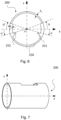
- Fig. 6 schematically depicts a cross section of the hollow susceptive casing (200) in the transverse plane (yz) according to an embodiment of the reaction chamber of the present invention.
- the susceptive casing exhibits an essentially cylindrical shape and extends along the longitudinal direction (x), perpendicular to the transverse plane.
- the susceptive casing features an internal surface (250) provided with protrusions (251, 252) adapted to support and position a reaction unit.
- the susceptive cases a first average thickness t 1 and a second average thickness t 2 > t 1 in the transverse plane, notwithstanding the protrusions (251, 252)).
- t 1 exhibit a thickness increase of 20-80%, preferably 30-60%, with respect to t 2 .
- Fig. 7 schematically depicts a cross section of the hollow susceptive casing (200) in the transverse plane (yz) according to an embodiment of the reaction chamber of the present invention.
- the susceptive casing exhibits an essentially cylindrical shape and extends along the longitudinal direction (x), perpendicular to the transverse plane (yz). To reduce the heating in correspondence of the central part of the reaction unit, not shown, the casing features an opening on the upper portion of the susceptor.
- the casing may exhibit a plurality of openings, which may be symmetrical with respect to the horizontal plane (xy), parallel to the substrates to be treated.
- the openings may be advantageously located in the substantially central portion of the susceptive casing in the longitudinal direction.
- Fig. 8 illustrates an embodiment of the reaction chamber (100) according to the invention, presenting a cross section in the transverse plane (yz), perpendicular to a longitudinal direction.
- the reaction chamber comprises a hollow susceptive casing (200) and a reaction unit (300).
- the susceptive casing extends along the longitudinal direction and features an internal surface (250) equipped with protrusions (251, 252) adapted to support, position the reaction unit (300).
- the latter is provided with releasable coupling means (331, 332) configured to engage with the protrusions (251, 252).
- Both the susceptive casing and the reaction feature an ovaloid cross section in the transverse plane.
- the similar, flattened shape of both elements improves heat transfer between the susceptive casing and the reaction via irradiation.
- the reaction unit (300) features a top wall (320), two curved lateral walls (330, 340), and a bottom wall (310).
- the bottom wall is equipped with a receiving area (311) adapted to lodge and rotate a substrate holder (315) supporting a substrate.
Landscapes
- Chemical & Material Sciences (AREA)
- Engineering & Computer Science (AREA)
- Metallurgy (AREA)
- Materials Engineering (AREA)
- Organic Chemistry (AREA)
- Chemical Kinetics & Catalysis (AREA)
- General Chemical & Material Sciences (AREA)
- Crystallography & Structural Chemistry (AREA)
- Mechanical Engineering (AREA)
- Inorganic Chemistry (AREA)
- Crystals, And After-Treatments Of Crystals (AREA)
- Chemical Vapour Deposition (AREA)
- Robotics (AREA)
Applications Claiming Priority (2)
| Application Number | Priority Date | Filing Date | Title |
|---|---|---|---|
| IT102023000024660A IT202300024660A1 (it) | 2023-11-21 | 2023-11-21 | Reattore con unità di reazione rimovibile |
| IT102023000024663A IT202300024663A1 (it) | 2023-11-21 | 2023-11-21 | Sistema di automazione per unità di reazione removibile di un reattore epitassiale |
Publications (1)
| Publication Number | Publication Date |
|---|---|
| EP4560055A1 true EP4560055A1 (de) | 2025-05-28 |
Family
ID=93520661
Family Applications (2)
| Application Number | Title | Priority Date | Filing Date |
|---|---|---|---|
| EP24214242.0A Pending EP4560055A1 (de) | 2023-11-21 | 2024-11-20 | Reaktor mit abnehmbarer reaktionseinheit |
| EP24214250.3A Active EP4560047B1 (de) | 2023-11-21 | 2024-11-20 | Automatisierungssystem für eine abnehmbare reaktionseinheit eines epitaxiereaktors |
Family Applications After (1)
| Application Number | Title | Priority Date | Filing Date |
|---|---|---|---|
| EP24214250.3A Active EP4560047B1 (de) | 2023-11-21 | 2024-11-20 | Automatisierungssystem für eine abnehmbare reaktionseinheit eines epitaxiereaktors |
Country Status (6)
| Country | Link |
|---|---|
| US (2) | US20250167028A1 (de) |
| EP (2) | EP4560055A1 (de) |
| JP (2) | JP2025084116A (de) |
| KR (2) | KR20250075515A (de) |
| CN (2) | CN120026390A (de) |
| TW (2) | TW202536258A (de) |
Citations (5)
| Publication number | Priority date | Publication date | Assignee | Title |
|---|---|---|---|---|
| US5879459A (en) * | 1997-08-29 | 1999-03-09 | Genus, Inc. | Vertically-stacked process reactor and cluster tool system for atomic layer deposition |
| EP1570107A1 (de) | 2002-12-10 | 2005-09-07 | E.T.C. Epitaxial Technology Center SRL | Suszeptorsystem |
| WO2021105841A1 (en) | 2019-11-25 | 2021-06-03 | Lpe S.P.A. | Substrate support device for a reaction chamber of an epitaxial reactor with gas flow rotation, reaction chamber and epitaxial reactor |
| IT202300024663A1 (it) | 2023-11-21 | 2025-05-21 | Lpe Spa | Sistema di automazione per unità di reazione removibile di un reattore epitassiale |
| IT202300024660A1 (it) | 2023-11-21 | 2025-05-21 | Lpe Spa | Reattore con unità di reazione rimovibile |
Family Cites Families (3)
| Publication number | Priority date | Publication date | Assignee | Title |
|---|---|---|---|---|
| US6174377B1 (en) * | 1997-03-03 | 2001-01-16 | Genus, Inc. | Processing chamber for atomic layer deposition processes |
| US20020137346A1 (en) * | 2001-03-12 | 2002-09-26 | Applied Materials. Inc. | Workpiece distribution and processing in a high throughput stacked frame |
| GB201701166D0 (en) * | 2017-01-24 | 2017-03-08 | Picofluidics Ltd | An apparatus for electrochemically processing semiconductor substrates |
-
2024
- 2024-11-20 KR KR1020240166628A patent/KR20250075515A/ko active Pending
- 2024-11-20 CN CN202411659913.4A patent/CN120026390A/zh active Pending
- 2024-11-20 CN CN202411660985.0A patent/CN120024719A/zh active Pending
- 2024-11-20 US US18/954,046 patent/US20250167028A1/en active Pending
- 2024-11-20 KR KR1020240166699A patent/KR20250075519A/ko active Pending
- 2024-11-20 US US18/953,993 patent/US20250163608A1/en active Pending
- 2024-11-20 TW TW113144606A patent/TW202536258A/zh unknown
- 2024-11-20 EP EP24214242.0A patent/EP4560055A1/de active Pending
- 2024-11-20 JP JP2024202386A patent/JP2025084116A/ja active Pending
- 2024-11-20 EP EP24214250.3A patent/EP4560047B1/de active Active
- 2024-11-20 TW TW113144540A patent/TW202531465A/zh unknown
- 2024-11-20 JP JP2024202387A patent/JP2025084117A/ja active Pending
Patent Citations (6)
| Publication number | Priority date | Publication date | Assignee | Title |
|---|---|---|---|---|
| US5879459A (en) * | 1997-08-29 | 1999-03-09 | Genus, Inc. | Vertically-stacked process reactor and cluster tool system for atomic layer deposition |
| EP1570107A1 (de) | 2002-12-10 | 2005-09-07 | E.T.C. Epitaxial Technology Center SRL | Suszeptorsystem |
| WO2021105841A1 (en) | 2019-11-25 | 2021-06-03 | Lpe S.P.A. | Substrate support device for a reaction chamber of an epitaxial reactor with gas flow rotation, reaction chamber and epitaxial reactor |
| US20220411961A1 (en) | 2019-11-25 | 2022-12-29 | Lpe S.P.A. | Substrate support device for a reaction chamber of an epitaxial reactor with gas flow rotation, reaction chamber and epitaxial reactor |
| IT202300024663A1 (it) | 2023-11-21 | 2025-05-21 | Lpe Spa | Sistema di automazione per unità di reazione removibile di un reattore epitassiale |
| IT202300024660A1 (it) | 2023-11-21 | 2025-05-21 | Lpe Spa | Reattore con unità di reazione rimovibile |
Also Published As
| Publication number | Publication date |
|---|---|
| CN120024719A (zh) | 2025-05-23 |
| KR20250075519A (ko) | 2025-05-28 |
| JP2025084116A (ja) | 2025-06-02 |
| KR20250075515A (ko) | 2025-05-28 |
| CN120026390A (zh) | 2025-05-23 |
| JP2025084117A (ja) | 2025-06-02 |
| EP4560047A1 (de) | 2025-05-28 |
| TW202536258A (zh) | 2025-09-16 |
| EP4560047B1 (de) | 2026-04-01 |
| TW202531465A (zh) | 2025-08-01 |
| US20250167028A1 (en) | 2025-05-22 |
| US20250163608A1 (en) | 2025-05-22 |
Similar Documents
| Publication | Publication Date | Title |
|---|---|---|
| JP2004507898A (ja) | 特に結晶質の基板上に、特に結晶質の層を沈積する装置および方法 | |
| EP3084034B1 (de) | Reaktionskammer zum epitaktischen wachstum mit einer lade-/entladevorrichtung und reaktor | |
| EP4560055A1 (de) | Reaktor mit abnehmbarer reaktionseinheit | |
| EP2975157A1 (de) | Gasstromflansch für einen rotierenden scheibenreaktor zur chemischen gasphasenabscheidung | |
| IT202300024663A1 (it) | Sistema di automazione per unità di reazione removibile di un reattore epitassiale | |
| EP0164928A2 (de) | Senkrechter Heisswandreaktor zur chemischen Abscheidung aus der Gasphase | |
| IT202300024660A1 (it) | Reattore con unità di reazione rimovibile | |
| CN116815320A (zh) | 碳化硅晶体生长装置、方法及碳化硅晶体 | |
| US20100037825A1 (en) | Differentiated-temperature reaction chamber | |
| JP2012216744A (ja) | 気相成長装置及び気相成長方法 | |
| JP2008034780A (ja) | エピタキシャルSiC膜付き半導体SiC基板の製造方法およびそのエピタキシャルSiC成膜装置 | |
| JP2013026358A (ja) | シャワープレート及び気相成長装置 | |
| US20260009154A1 (en) | Reaction chamber assembly | |
| KR101832980B1 (ko) | 가열 단계, 처리 단계 및 냉각 단계를 갖는 열 처리 방법 | |
| EP4560048A1 (de) | Mehrkammeranordnung zur handhabung von entfernbaren epitaxialreaktionseinheiten | |
| KR20130029587A (ko) | 화학기상증착장치의 가스공급유닛 및 이의 제조방법 | |
| US20250146172A1 (en) | Fast cooling of reactor from high temperatures | |
| EP4596749A1 (de) | Reaktorgehäuseanordnung | |
| JP7744663B2 (ja) | 高温用気相成長装置および半導体結晶膜の成長方法 | |
| US12000046B1 (en) | Load assemblies for loading parts in a furnace | |
| KR20180115044A (ko) | 화학 기상 증착용 반응기 및 이를 포함하는 화학 기상 증착 장치 |
Legal Events
| Date | Code | Title | Description |
|---|---|---|---|
| PUAI | Public reference made under article 153(3) epc to a published international application that has entered the european phase |
Free format text: ORIGINAL CODE: 0009012 |
|
| STAA | Information on the status of an ep patent application or granted ep patent |
Free format text: STATUS: THE APPLICATION HAS BEEN PUBLISHED |
|
| AK | Designated contracting states |
Kind code of ref document: A1 Designated state(s): AL AT BE BG CH CY CZ DE DK EE ES FI FR GB GR HR HU IE IS IT LI LT LU LV MC ME MK MT NL NO PL PT RO RS SE SI SK SM TR |
|
| STAA | Information on the status of an ep patent application or granted ep patent |
Free format text: STATUS: REQUEST FOR EXAMINATION WAS MADE |
|
| 17P | Request for examination filed |
Effective date: 20251105 |