EP4560104A1 - Dispositif de montage d'un dispositif de réception pour au moins un moyen de fixation d'une fixation de rebord de fenêtre dans un mur ainsi que module correspondant - Google Patents
Dispositif de montage d'un dispositif de réception pour au moins un moyen de fixation d'une fixation de rebord de fenêtre dans un mur ainsi que module correspondant Download PDFInfo
- Publication number
- EP4560104A1 EP4560104A1 EP24213566.3A EP24213566A EP4560104A1 EP 4560104 A1 EP4560104 A1 EP 4560104A1 EP 24213566 A EP24213566 A EP 24213566A EP 4560104 A1 EP4560104 A1 EP 4560104A1
- Authority
- EP
- European Patent Office
- Prior art keywords
- masonry
- receiving device
- support plate
- layer
- carrier plate
- Prior art date
- Legal status (The legal status is an assumption and is not a legal conclusion. Google has not performed a legal analysis and makes no representation as to the accuracy of the status listed.)
- Pending
Links
Images
Classifications
-
- E—FIXED CONSTRUCTIONS
- E06—DOORS, WINDOWS, SHUTTERS, OR ROLLER BLINDS IN GENERAL; LADDERS
- E06B—FIXED OR MOVABLE CLOSURES FOR OPENINGS IN BUILDINGS, VEHICLES, FENCES OR LIKE ENCLOSURES IN GENERAL, e.g. DOORS, WINDOWS, BLINDS, GATES
- E06B1/00—Border constructions of openings in walls, floors, or ceilings; Frames to be rigidly mounted in such openings
- E06B1/70—Sills; Thresholds
Definitions
- the invention relates to a device for arranging a receiving device for fastening means of a window sill attachment in masonry according to the preamble of claim 1.
- a receiving device for fastening means of a window sill attachment in masonry according to the preamble of claim 1.
- the wall is usually first constructed and then the window sill is mounted on top of the wall in the area of the window opening. This usually requires screws to be inserted into the masonry.
- the bricks themselves or the mortar layers connecting them may be damaged. This can lead to the masonry becoming leaky and thus being damaged by weathering, which can lead to cracks and moisture damage in the masonry.
- the DE 10 2015 224 314 A1 Describes a fastening element for the fall-proof attachment of a structural element to a building structure. It features several round holes for screwing the fastening element into the masonry, as well as a socket for receiving the structural element.
- the disadvantage of this device is that the screws must be inserted into the masonry, which can damage the masonry or mortar, leading to leaks.
- a device for fastening at least one element to a masonry has two elongated parts that are arranged perpendicular to each other and are installed in the masonry.
- the first elongated part points outwards, while the second elongated part is arranged in a butt joint and a hand hole, wherein the hand hole is filled with mortar.
- the second elongated part can be a cylindrically shaped reinforcing steel.
- the end of the first elongated section is accessible from the wide side of the masonry and not from the top. Installing it rotated by 90 degrees to make the first elongated section accessible from above is not as easy, since the stability of the fastening is achieved here by the second elongated section engaging in a handhole. Engaging it in a layer joint, for example, would not achieve the same hold.
- the fastening consists of a roughly T-shaped anchor plate to which the window sill is attached.
- the elongated section of the T-shaped plate is arranged in a butt joint in the uppermost layer of the masonry.
- At the lower end there is a flange that engages under a brick in the uppermost layer of the masonry.
- the disadvantage here is that the window sills used must fit exactly with the permanently installed device, because the fastening devices for the window sill are formed integrally with the anchor plate.
- the flange that engages under a brick is quite small and only secures the anchor plate in one direction. This may not be sufficient, especially with higher loads from wind or similar.
- the object of the invention is therefore to avoid the aforementioned disadvantages and to provide a way to introduce fastening means for a window sill into the masonry and to securely fasten them there without damaging the masonry.
- a further object of the invention is to provide an assembly comprising a masonry structure and at least one device.
- the device comprises a support plate which can be inserted into a layer joint below the top layer of the masonry. Furthermore, the The device according to the invention has a receiving device that is arranged on the support plate and projects away from it at approximately a right angle. This makes it possible for the receiving device to be arranged in a butt joint in the masonry. When installed in the masonry, the receiving device then extends through a butt joint in the uppermost layer of the masonry and is accessible from the top side of the masonry. The fastening element(s) of the window sill can then be inserted into this receiving device without damaging the masonry during installation. The receiving device is mounted and held in the masonry by the support plate.
- the device according to the invention is very flexible in use and is therefore compatible with all DIN and special formats.
- the support plate has a flat, planar shape whose length is greater than its width.
- the receiving device is arranged centrally on the support plate, both in the longitudinal direction and in the width direction of the support plate.
- the support plate is therefore suitable for being arranged under at least two bricks of the masonry in order to provide a good and stable hold.
- the support plate can also be lengthened or widened, allowing it to be positioned under more stones. Positioning the support device in the center of the support plate ensures even and good force distribution.
- Fasteners such as screws or bolts can then be inserted into the receiving device.
- One or more recesses can be provided, each having an internal thread into which the screws can be inserted.
- the receiving device can also comprise one or more sleeves into which the fastening means(s) can be received. If the fastening means are screws, the sleeves can advantageously have an internal thread.
- the sleeves can be arranged individually or in groups directly on the carrier plate or within the receiving device in a housing.
- the support plate has one or more openings or perforations into which the mortar from the layer joint can penetrate, at least in certain areas.
- the shape and arrangement of these openings or perforations can vary.
- the support plate can also be made of perforated sheet metal. Since the mortar penetrates the openings or perforations during installation, the support plate can grip the layer joint particularly well, and the receiving device is particularly well secured in the masonry.
- the carrier plate can be made of a wide variety of materials.
- the carrier plate can be designed as a metal profile, which preferably has at least one opening.
- the carrier plate can also be configured as a metallic mesh, woven fabric, or knitted fabric.
- the textile material can then be designed such that the mesh size or thread density is selected so that the material forms the openings into which the mortar can penetrate.
- the carrier plate can be rigid (e.g., as a profile) or movable (e.g., as a metallic mesh).
- fastening options include, but are not limited to, welding, gluing, riveting, screwing, or even a one-piece construction of the two components. This list is not exhaustive. It is important in this context that both components are securely connected to each other so that the fastener, and thus the window sill, can be securely attached to the masonry.
- the support plate has a projection on its underside that protrudes from the underside. This projection can then be inserted into a butt joint in the second layer of the masonry. This holds the support plate even more securely in the layer joint and prevents it from slipping.
- the projection is particularly preferably on the The support plate is arranged displaceably, in particular through at least one elongated hole in the support plate. This can then be arranged in the direction of the longitudinal axis of the support plate, so that the projection is displaceable in the longitudinal direction of the support plate in order to be aligned with the butt joint.
- the projection is designed as a clamp that can be clamped in a butt joint or on the bricks. Alternatively, the projection can also be designed as a dowel.
- the invention also encompasses an assembly consisting of a masonry structure and at least one device according to the invention.
- the device is arranged beneath the topmost layer of bricks, such that the support plate is arranged beneath at least two bricks in the layer joint.
- the receiving device then penetrates a butt joint of the topmost layer in such a way that it is accessible from the top side of the masonry. In this way, a window sill or another object can be attached to the receiving device without damaging the masonry or the mortar.
- the length of the receiving device is adapted to the height of a brick, such that different devices are provided for bricks of different heights.
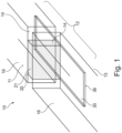
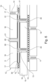
- a device according to the invention is shown, which is arranged in a masonry 10.
- the carrier plate 30 is arranged in a layer joint 13 below the uppermost layer 12 of the masonry 10 such that the receiving device 20 protrudes into a butt joint 14 between two bricks 16 of the masonry 10.
- a plastic profile 21 is provided as the receiving device 20, into which holes can be made, for example, for receiving fastening means such as screws or the like. In this position, the receiving device 20 is accessible from the upper side 11 of the masonry 10 in order to insert the fastening means.
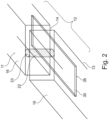
- FIG. 2 shows a second embodiment of the invention.
- a sleeve 22 is provided as the receiving device 20, which in this embodiment has an internal thread 23.
- a fastening means such as a screw or threaded rod can be screwed into this.
- multiple sleeves 22 can also be attached to the support plate 30.
- the internal thread 23 of the sleeve 22 is also accessible from the top side 11 of the masonry 10.
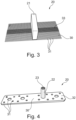
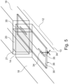
- the Figs. 3 and 4 show the carrier plates 30 and the receiving devices 20 from the Fig. 1 and 2 without masonry 10. It can be seen that the receiving devices 20 are approximately perpendicular to the in a layer joint 13 introduced support plates 30 are arranged to be introduced into a butt joint 14 of the masonry 10, which are also arranged approximately perpendicular to the layer joints 13 of the masonry 10.
- the carrier plate 30 made of Fig. 3 consists here of a fabric 33 which is quite coarsely woven and thus has a plurality of openings 31 into which mortar from the layer joint 13 can penetrate in order to firmly fix the support plate 30 in the masonry 10.
- FIG. 4 A support plate 30 made of a rigid material such as metal or plastic is shown, into which several openings 31 are also introduced.
- the mortar of the layer joint 13 can also penetrate into these openings 31 and become embedded there in order to better secure the support plate in the masonry 10.
- several sleeves 22 can also be provided. These can then be inserted into the same or different butt joints 14, depending on the arrangement.
- a support plate 30 is arranged below the uppermost layer 12 of the masonry 10, and a plastic profile 21 is provided as the receiving device 20.
- a projection 34 is arranged, which in this exemplary embodiment has the shape of a clamp. Other shapes of the projection 34 are also conceivable and encompassed by the invention, such as pins, dowels, or the like. The projection 34 can then penetrate into a butt joint 14 in the second layer 15 of the masonry 10 in order to hold the support plate 30 even more securely.
- Fig. 6 is a schematic structure of the masonry 10 in an embodiment according to Fig. 5 shown.
- a total of three layers can be seen of bricks 16 that form the masonry 10.
- the support plate 30 is arranged in a layer joint 13 and is surrounded by mortar 17 and secured by it.
- the receiving device 20 is arranged perpendicular to the support plate 30 and extends through a butt joint 14 of the uppermost layer 12 of the masonry 10.
- a projection 34 is inserted into an elongated hole 35 in the support plate 30. This projection projects approximately vertically downwards from the support plate and extends through a butt joint 14 in the second layer 15 of the masonry 10. This secures the support plate particularly securely in the masonry 10.
- the device according to the invention is not limited to the exemplary embodiments presented here. Further modifications are also encompassed by the inventive concept.
Landscapes
- Engineering & Computer Science (AREA)
- Civil Engineering (AREA)
- Structural Engineering (AREA)
- Connection Of Plates (AREA)
- Joining Of Building Structures In Genera (AREA)
Applications Claiming Priority (1)
| Application Number | Priority Date | Filing Date | Title |
|---|---|---|---|
| DE202023106942.8U DE202023106942U1 (de) | 2023-11-23 | 2023-11-23 | Vorrichtung zur Anordnung einer Aufnahmeeinrichtung für wenigstens ein Befestigungsmittel einer Fensterbankbefestigung in einem Mauerwerk |
Publications (1)
| Publication Number | Publication Date |
|---|---|
| EP4560104A1 true EP4560104A1 (fr) | 2025-05-28 |
Family
ID=89809154
Family Applications (1)
| Application Number | Title | Priority Date | Filing Date |
|---|---|---|---|
| EP24213566.3A Pending EP4560104A1 (fr) | 2023-11-23 | 2024-11-18 | Dispositif de montage d'un dispositif de réception pour au moins un moyen de fixation d'une fixation de rebord de fenêtre dans un mur ainsi que module correspondant |
Country Status (2)
| Country | Link |
|---|---|
| EP (1) | EP4560104A1 (fr) |
| DE (1) | DE202023106942U1 (fr) |
Citations (6)
| Publication number | Priority date | Publication date | Assignee | Title |
|---|---|---|---|---|
| US2697932A (en) | 1951-08-03 | 1954-12-28 | Overly Mfg Company | Window sill |
| EP0544953A1 (fr) * | 1991-12-04 | 1993-06-09 | Ibstock Building Products Limited | Procédé et dispositif de fixation d'éléments de construction ou d'autres articles à une structure de support |
| US20030197107A1 (en) * | 2000-04-13 | 2003-10-23 | Herbison Francis Dennis | Securement member |
| CH705239A2 (de) | 2011-07-15 | 2013-01-15 | Wipf & Ammann Bau Ag | Vorrichtung zur Befestigung von mindestens einem Element, insbesondere einer Abschalung, an einem Mauerwerk. |
| DE102015224314A1 (de) | 2014-12-05 | 2016-06-09 | Vbh Holding Ag | Befestigungselement |
| US20190352900A1 (en) * | 2018-05-18 | 2019-11-21 | Cetres Holdings, Llc | Concrete boss anchor |
-
2023
- 2023-11-23 DE DE202023106942.8U patent/DE202023106942U1/de active Active
-
2024
- 2024-11-18 EP EP24213566.3A patent/EP4560104A1/fr active Pending
Patent Citations (6)
| Publication number | Priority date | Publication date | Assignee | Title |
|---|---|---|---|---|
| US2697932A (en) | 1951-08-03 | 1954-12-28 | Overly Mfg Company | Window sill |
| EP0544953A1 (fr) * | 1991-12-04 | 1993-06-09 | Ibstock Building Products Limited | Procédé et dispositif de fixation d'éléments de construction ou d'autres articles à une structure de support |
| US20030197107A1 (en) * | 2000-04-13 | 2003-10-23 | Herbison Francis Dennis | Securement member |
| CH705239A2 (de) | 2011-07-15 | 2013-01-15 | Wipf & Ammann Bau Ag | Vorrichtung zur Befestigung von mindestens einem Element, insbesondere einer Abschalung, an einem Mauerwerk. |
| DE102015224314A1 (de) | 2014-12-05 | 2016-06-09 | Vbh Holding Ag | Befestigungselement |
| US20190352900A1 (en) * | 2018-05-18 | 2019-11-21 | Cetres Holdings, Llc | Concrete boss anchor |
Also Published As
| Publication number | Publication date |
|---|---|
| DE202023106942U1 (de) | 2024-01-08 |
Similar Documents
| Publication | Publication Date | Title |
|---|---|---|
| EP3150779B1 (fr) | Montage d'un coffrage de mur et système d'ancrage à élément de dimension modulaire | |
| DE3224986C2 (de) | Vorrichtung zur Befestigung von Montageteilen an einer Betonwand | |
| DE102016000829A1 (de) | Vorrichtung zur Befestigung und/oder Ausrichtung von Bodenbelägen | |
| DE202007018765U1 (de) | Halterung für Verkleidungselemente bzw. eine Unterkonstruktion für Verkleidungselemente | |
| DE202005006528U1 (de) | Befestigungsprofil | |
| DE102014106068B4 (de) | Vorrichtung zur Verbindung zweier einander gegenüberliegender plattenförmiger Schalungselemente | |
| DE102022114961A1 (de) | Anschlussvorrichtung, Deckenschalungssystem mit Anschlussvorrichtung sowie Verfahren zur Herstellung einer Deckenschalung | |
| DE102009056332A1 (de) | Verbindungselement für Stützen | |
| EP3951114B1 (fr) | Dispositif de fixation | |
| EP1845219B1 (fr) | Dispositif de support pour revêtements muraux | |
| DE202018103083U1 (de) | Befestigungssystem mit Kraftverteilung | |
| DE1942604A1 (de) | Einrichtung zum Verankern eines Teiles an einem anderen Teil eines Baukoerpers | |
| AT508798A2 (de) | Schalung | |
| EP2458302A1 (fr) | Elément de liaison et dispositif de fixation de modules solaires | |
| DE102004022279B4 (de) | Vorrichtung zur Befestigung von Dämmstoffelementen an ebenen Flächen | |
| DE202023106942U1 (de) | Vorrichtung zur Anordnung einer Aufnahmeeinrichtung für wenigstens ein Befestigungsmittel einer Fensterbankbefestigung in einem Mauerwerk | |
| DE202020102247U1 (de) | Befestigungsvorrichtung und Fassadenkonstruktion hiermit | |
| DE10161426A1 (de) | Verankerung für verspannte Konstruktionen | |
| AT500503A1 (de) | Ankerhalter | |
| DE102018203080A1 (de) | Fundamentsystem für die lagerung von flächig nebeneinander angeordneten solarpaneelen | |
| DE202025104335U1 (de) | Vorrichtung zur Montage eines Fensterrahmens an einem Rolladenkasten | |
| AT404049B (de) | Auftrittsziegel | |
| DE2733448C3 (de) | Hängedecke | |
| DE20000552U1 (de) | Profilschienensystem | |
| EP4647613A1 (fr) | Module pour la fixation d'un composant à fixer sur un composant fixe |
Legal Events
| Date | Code | Title | Description |
|---|---|---|---|
| PUAI | Public reference made under article 153(3) epc to a published international application that has entered the european phase |
Free format text: ORIGINAL CODE: 0009012 |
|
| STAA | Information on the status of an ep patent application or granted ep patent |
Free format text: STATUS: THE APPLICATION HAS BEEN PUBLISHED |
|
| AK | Designated contracting states |
Kind code of ref document: A1 Designated state(s): AL AT BE BG CH CY CZ DE DK EE ES FI FR GB GR HR HU IE IS IT LI LT LU LV MC ME MK MT NL NO PL PT RO RS SE SI SK SM TR |
|
| STAA | Information on the status of an ep patent application or granted ep patent |
Free format text: STATUS: REQUEST FOR EXAMINATION WAS MADE |
|
| 17P | Request for examination filed |
Effective date: 20251113 |
|
| STAA | Information on the status of an ep patent application or granted ep patent |
Free format text: STATUS: EXAMINATION IS IN PROGRESS |
|
| 17Q | First examination report despatched |
Effective date: 20260320 |