EP4560136A1 - Pitchanordnung für eine windturbine mit minimiertem mikropitch - Google Patents
Pitchanordnung für eine windturbine mit minimiertem mikropitch Download PDFInfo
- Publication number
- EP4560136A1 EP4560136A1 EP24214569.6A EP24214569A EP4560136A1 EP 4560136 A1 EP4560136 A1 EP 4560136A1 EP 24214569 A EP24214569 A EP 24214569A EP 4560136 A1 EP4560136 A1 EP 4560136A1
- Authority
- EP
- European Patent Office
- Prior art keywords
- pitch
- pinion
- assembly
- pitch drive
- hub
- Prior art date
- Legal status (The legal status is an assumption and is not a legal conclusion. Google has not performed a legal analysis and makes no representation as to the accuracy of the status listed.)
- Pending
Links
Images




Classifications
-
- F—MECHANICAL ENGINEERING; LIGHTING; HEATING; WEAPONS; BLASTING
- F03—MACHINES OR ENGINES FOR LIQUIDS; WIND, SPRING, OR WEIGHT MOTORS; PRODUCING MECHANICAL POWER OR A REACTIVE PROPULSIVE THRUST, NOT OTHERWISE PROVIDED FOR
- F03D—WIND MOTORS
- F03D1/00—Wind motors with rotation axis substantially parallel to the air flow entering the rotor
- F03D1/06—Rotors
- F03D1/065—Rotors characterised by their construction elements
- F03D1/0658—Arrangements for fixing wind-engaging parts to a hub
- F03D1/0662—Arrangements for fixing wind-engaging parts to a hub using kinematic linkage, e.g. tilt
- F03D1/0664—Pitch arrangements
-
- F—MECHANICAL ENGINEERING; LIGHTING; HEATING; WEAPONS; BLASTING
- F03—MACHINES OR ENGINES FOR LIQUIDS; WIND, SPRING, OR WEIGHT MOTORS; PRODUCING MECHANICAL POWER OR A REACTIVE PROPULSIVE THRUST, NOT OTHERWISE PROVIDED FOR
- F03D—WIND MOTORS
- F03D7/00—Controlling wind motors
- F03D7/02—Controlling wind motors the wind motors having rotation axis substantially parallel to the air flow entering the rotor
- F03D7/022—Adjusting aerodynamic properties of the blades
- F03D7/0224—Adjusting blade pitch
-
- F—MECHANICAL ENGINEERING; LIGHTING; HEATING; WEAPONS; BLASTING
- F03—MACHINES OR ENGINES FOR LIQUIDS; WIND, SPRING, OR WEIGHT MOTORS; PRODUCING MECHANICAL POWER OR A REACTIVE PROPULSIVE THRUST, NOT OTHERWISE PROVIDED FOR
- F03D—WIND MOTORS
- F03D1/00—Wind motors with rotation axis substantially parallel to the air flow entering the rotor
- F03D1/06—Rotors
- F03D1/065—Rotors characterised by their construction elements
- F03D1/0658—Arrangements for fixing wind-engaging parts to a hub
- F03D1/0662—Arrangements for fixing wind-engaging parts to a hub using kinematic linkage, e.g. tilt
- F03D1/0664—Pitch arrangements
- F03D1/0667—Pitch arrangements characterized by the actuator arrangements
-
- F—MECHANICAL ENGINEERING; LIGHTING; HEATING; WEAPONS; BLASTING
- F03—MACHINES OR ENGINES FOR LIQUIDS; WIND, SPRING, OR WEIGHT MOTORS; PRODUCING MECHANICAL POWER OR A REACTIVE PROPULSIVE THRUST, NOT OTHERWISE PROVIDED FOR
- F03D—WIND MOTORS
- F03D15/00—Transmission of mechanical power
-
- F—MECHANICAL ENGINEERING; LIGHTING; HEATING; WEAPONS; BLASTING
- F16—ENGINEERING ELEMENTS AND UNITS; GENERAL MEASURES FOR PRODUCING AND MAINTAINING EFFECTIVE FUNCTIONING OF MACHINES OR INSTALLATIONS; THERMAL INSULATION IN GENERAL
- F16H—GEARING
- F16H55/00—Elements with teeth or friction surfaces for conveying motion; Worms, pulleys or sheaves for gearing mechanisms
- F16H55/02—Toothed members; Worms
- F16H55/06—Use of materials; Use of treatments of toothed members or worms to affect their intrinsic material properties
-
- F—MECHANICAL ENGINEERING; LIGHTING; HEATING; WEAPONS; BLASTING
- F16—ENGINEERING ELEMENTS AND UNITS; GENERAL MEASURES FOR PRODUCING AND MAINTAINING EFFECTIVE FUNCTIONING OF MACHINES OR INSTALLATIONS; THERMAL INSULATION IN GENERAL
- F16H—GEARING
- F16H55/00—Elements with teeth or friction surfaces for conveying motion; Worms, pulleys or sheaves for gearing mechanisms
- F16H55/02—Toothed members; Worms
- F16H55/17—Toothed wheels
- F16H55/18—Special devices for taking up backlash
-
- F—MECHANICAL ENGINEERING; LIGHTING; HEATING; WEAPONS; BLASTING
- F16—ENGINEERING ELEMENTS AND UNITS; GENERAL MEASURES FOR PRODUCING AND MAINTAINING EFFECTIVE FUNCTIONING OF MACHINES OR INSTALLATIONS; THERMAL INSULATION IN GENERAL
- F16H—GEARING
- F16H57/00—General details of gearing
- F16H57/12—Arrangements for adjusting or for taking-up backlash not provided for elsewhere
-
- F—MECHANICAL ENGINEERING; LIGHTING; HEATING; WEAPONS; BLASTING
- F03—MACHINES OR ENGINES FOR LIQUIDS; WIND, SPRING, OR WEIGHT MOTORS; PRODUCING MECHANICAL POWER OR A REACTIVE PROPULSIVE THRUST, NOT OTHERWISE PROVIDED FOR
- F03D—WIND MOTORS
- F03D17/00—Monitoring or testing of wind motors, e.g. diagnostics
- F03D17/027—Monitoring or testing of wind motors, e.g. diagnostics characterised by the component being monitored or tested
- F03D17/029—Blade pitch or yaw drive systems, e.g. pitch or yaw angle
-
- F—MECHANICAL ENGINEERING; LIGHTING; HEATING; WEAPONS; BLASTING
- F05—INDEXING SCHEMES RELATING TO ENGINES OR PUMPS IN VARIOUS SUBCLASSES OF CLASSES F01-F04
- F05B—INDEXING SCHEME RELATING TO WIND, SPRING, WEIGHT, INERTIA OR LIKE MOTORS, TO MACHINES OR ENGINES FOR LIQUIDS COVERED BY SUBCLASSES F03B, F03D AND F03G
- F05B2260/00—Function
- F05B2260/40—Transmission of power
- F05B2260/403—Transmission of power through the shape of the drive components
- F05B2260/4031—Transmission of power through the shape of the drive components as in toothed gearing
-
- F—MECHANICAL ENGINEERING; LIGHTING; HEATING; WEAPONS; BLASTING
- F16—ENGINEERING ELEMENTS AND UNITS; GENERAL MEASURES FOR PRODUCING AND MAINTAINING EFFECTIVE FUNCTIONING OF MACHINES OR INSTALLATIONS; THERMAL INSULATION IN GENERAL
- F16H—GEARING
- F16H57/00—General details of gearing
- F16H57/12—Arrangements for adjusting or for taking-up backlash not provided for elsewhere
- F16H2057/123—Arrangements for adjusting or for taking-up backlash not provided for elsewhere using electric control means
-
- Y—GENERAL TAGGING OF NEW TECHNOLOGICAL DEVELOPMENTS; GENERAL TAGGING OF CROSS-SECTIONAL TECHNOLOGIES SPANNING OVER SEVERAL SECTIONS OF THE IPC; TECHNICAL SUBJECTS COVERED BY FORMER USPC CROSS-REFERENCE ART COLLECTIONS [XRACs] AND DIGESTS
- Y02—TECHNOLOGIES OR APPLICATIONS FOR MITIGATION OR ADAPTATION AGAINST CLIMATE CHANGE
- Y02E—REDUCTION OF GREENHOUSE GAS [GHG] EMISSIONS, RELATED TO ENERGY GENERATION, TRANSMISSION OR DISTRIBUTION
- Y02E10/00—Energy generation through renewable energy sources
- Y02E10/70—Wind energy
- Y02E10/72—Wind turbines with rotation axis in wind direction
Definitions
- the present disclosure relates generally to wind turbines and, more particularly, to pitch assemblies for wind turbines and related methods that minimize micro-pitching.
- Wind power is considered one of the cleanest, most environmentally friendly energy sources presently available, and wind turbines have gained increased attention in this regard.
- a modern wind turbine typically includes a tower, a generator, a gearbox, a nacelle, and rotatable hub having one or more rotor blades mounted thereto.
- the rotor blades capture kinetic energy of wind using known airfoil principles.
- the rotor blades typically have the cross-sectional profile of an airfoil such that, during operation, air flows over the rotor blades producing a pressure difference between the sides. Consequently, a lift force, which is directed from a pressure side towards a suction side, acts on each of the rotor blades.
- the lift force generates torque on the main rotor shaft, which is typically geared to the generator for producing electricity.
- At least some known wind turbines also include a pitch assembly having a pitch bearing coupled between one of the rotor blades and the hub, and a pitch drive mechanism for use in positioning the rotor blade attached to the pitch bearing. Accordingly, the pitch assembly is operated to adjust the pitch of the rotor blade.
- the pitch bearing includes gear teeth that engage the pitch drive mechanism for rotation of the rotor blade about a pitch axis.
- Backlash i.e., clearance between mating components
- Such backlash can cause micro-pitching, which causes damage to the pitch bearing.
- the present disclosure is directed to a pitch assembly and method for preventing micro-pitching in a pitch assembly of a wind turbine.
- the present disclosure is directed to a pitch assembly for a wind turbine.
- the pitch assembly includes a pitch bearing comprising an inner race, an outer race, and a plurality of gear teeth arranged on one of the inner race or the outer race.
- the pitch assembly further includes a pitch drive mechanism having a pitch drive motor and a primary pitch drive pinion.
- the primary pitch drive pinion is configured to rotate one of the inner race or the outer race of the pitch bearing about a pitch axis by engaging with a first set of the plurality of gear teeth.
- the pitch assembly also includes a secondary pinion engaging a second set of the plurality of gear teeth.
- the secondary pinion is constructed of a deformable material such that backlash is eliminated between the secondary pinion and the plurality of gear teeth, thereby minimizing micro-pitching of the pitch assembly.
- the present disclosure is directed to a method of minimizing micro-pitching of a pitch assembly of a wind turbine.
- the method includes securing a pitch bearing having an inner race, an outer race, and a plurality of gear teeth arranged on one of the inner race or the outer race to a hub of the wind turbine.
- the method further includes securing a pitch drive mechanism having a pitch drive motor and a primary pitch drive pinion to the hub such that the primary pitch drive pinion engages with a first set of the plurality of gear teeth.
- the method includes engaging a secondary pinion with a second set of the plurality of gear teeth.
- the secondary pinion is constructed of a deformable material.
- the method includes rotating one of the inner race or the outer race of the pitch bearing about a pitch axis via the pitch drive mechanism, wherein the deformable material allows the secondary pinion to rotate without backlash between the secondary pinion and the plurality of gear teeth, thereby minimizing micro-pitching of the pitch assembly.
- the present disclosure is directed to a pitch drive mechanism for a wind turbine.
- the pitch drive mechanism includes a pitch drive motor, a primary pitch drive pinion configured to rotate one of an inner race or an outer race of a pitch bearing about a pitch axis by engaging with a first set of a plurality of gear teeth of one of the inner race or the outer race, and a secondary pinion configured to engage a second set of the plurality of gear teeth.
- the secondary pinion is constructed of a deformable material such that backlash is eliminated between the secondary pinion and the plurality of gear teeth, thereby minimizing micro-pitching of the pitch assembly.
- the present disclosure is directed to a pitch assembly for a wind turbine that utilizes a secondary pinion mounted on a hub of the wind turbine.
- the pitch assembly includes a pitch bearing having an inner race, an outer race, and a plurality of gear teeth arranged on one of the inner race or the outer race.
- the pitch assembly includes a pitch drive mechanism having a pitch drive motor and a primary pitch drive pinion configured to rotate one of the inner race or the outer race about a pitch axis by engaging with a first set of the plurality of gear teeth.
- the secondary pinion is constructed of a deformable material.
- the secondary pinion may be mechanically connected to a rotational device, such as a double-rachet mechanism, and engages a second set of the plurality of gear teeth. Accordingly, the deformable material of the secondary pinion allows for backlash between the secondary pinion and the plurality of gear teeth to be eliminated (or negligible), thereby minimizing micro-pitching of the pitch assembly.
- the secondary pinion is configured to rotate only when a torque at the secondary pinion exceeds a torque threshold (e.g., such as a bearing starting torque) so as to minimize micro-pitching of the pitch assembly. In an embodiment, this torque value is already accounted for in the pitch drive mechanism calculation, hence no additional load is applied on the pitch drive mechanism.
- a torque threshold e.g., such as a bearing starting torque
- FIG. 1 illustrates a schematic view of an embodiment of a wind turbine 100 according to the present disclosure.
- the wind turbine 100 is a horizontal-axis wind turbine.
- the wind turbine 100 may be a vertical-axis wind turbine.
- the wind turbine 100 includes a tower 102 extending from and coupled to a supporting surface 104.
- the tower 102 is coupled to the supporting surface 104 by either anchor bolts or by a foundation mounting piece (neither shown).
- the wind turbine 100 further includes a nacelle 106 coupled to the tower 102, and a rotor 108 is coupled to the nacelle 106.
- the rotor 108 includes a rotatable hub 110 and a plurality of rotor blades 112 coupled to hub 110.
- the rotor 108 includes three rotor blades 112.
- the rotor 108 may have any number of rotor blades 112 that enables the wind turbine 100 to function as described herein.
- the tower 102 may be any suitable height or construction that enables the wind turbine 100 to function as described herein.
- the rotor blades 112 are spaced about the hub 110 to facilitate rotating the rotor 108, thereby transferring kinetic energy from wind 124 into usable mechanical energy, and subsequently, electrical energy. Further, the rotor 108 and the nacelle 106 are rotated about the tower 102 on a yaw axis 116 to control the perspective of rotor blades 112 with respect to the direction of the wind 124.
- the rotor blades 112 are mated to the hub 110 by coupling a blade root portion 120 to the hub 110 at a plurality of load transfer regions 122.
- the load transfer regions 122 each have a hub load transfer region and a blade load transfer region (both not shown in FIG. 1 ).
- Each rotor blade 112 also includes a blade tip portion 125. As wind 124 contacts each rotor blade 112, blade lift forces are induced to each rotor blade 112 and rotation of rotor 108 about an axis of rotation 114 is induced as blade tip portions 125 are accelerated.
- a pitch angle (not shown) of the rotor blades 112 may be changed by a pitch assembly 130. Specifically, increasing a pitch angle of rotor blade(s) 112 decreases an amount of blade surface area 126 exposed to the wind 124 and, conversely, decreasing the pitch angle of the rotor blade(s) 112 increases an amount of blade surface area 126 exposed to the wind 124.
- the pitch angles of the rotor blades 112 are adjusted about a pitch axis 118 for each rotor blade 112. In an embodiment, the pitch angles of rotor blades 112 are controlled individually. Alternatively, the pitch of rotor blades 112 may be controlled as a group.
- the nacelle 106 includes three pitch assemblies 130 that are each coupled to a respective rotor blade 112 (shown in FIG. 1 ), wherein the pitch assembly 130 modulates the pitch of each respective rotor blade 112 along the pitch axis 118. Only one of three pitch assemblies 130 is illustrated in FIG. 2 .
- each pitch assembly 130 includes at least one pitch drive motor 131.
- the pitch drive motor 131 is any motor driven by electrical power and/or a hydraulic system that enables the pitch assembly 130 to function as described herein.
- the pitch assembly 130 may include any suitable structure, configuration, arrangement, and/or components such as, but not limited to, hydraulic cylinders, springs, and/or servomechanisms.
- the pitch assembly 130 may be driven by any suitable means such as, but not limited to, hydraulic fluid, and/or mechanical power, such as, but not limited to, induced spring forces and/or electromagnetic forces.
- the nacelle 106 may also house an electric generator 132 rotatably coupled to the rotor 108 by a rotor shaft 134 (sometimes referred to as either a main shaft or a low-speed shaft), a gearbox 136, a high-speed shaft 138, and a coupling 140.
- rotation of the rotor shaft 134 rotatably drives the gearbox 136 that subsequently drives the high-speed shaft 138.
- the high-speed shaft 138 rotatably drives the generator 132 with the coupling 140 and rotation of the high-speed shaft 138 facilitates production of electrical power by the generator 132.
- the gearbox 136 and the generator 132 are supported by supports 142 and 144, respectively.
- the gearbox 136 utilizes a dual path geometry to drive the high-speed shaft 138.
- the rotor shaft 134 may be coupled directly to the generator 132 with the coupling 140.
- the nacelle 106 also includes a yaw drive mechanism 146 that may be used to rotate the nacelle 106 and the rotor 108 about the yaw axis 116 ( FIG. 1 ) to control the perspective of the rotor blades 112 with respect to the direction of the wind 124.
- the nacelle 106 may also include at least one meteorological mast 148 that includes a wind vane and anemometer (neither shown in FIG. 2 ).
- the mast 148 provides information to a turbine control system 150 that may include wind direction and/or wind speed.
- the pitch assembly 130 may also be coupled to the turbine control system 150 for control thereby.
- the nacelle 106 may also include main, or forward and aft, support bearings 152 and 154, respectively.
- the support bearings 152 and 154 facilitate radial support and alignment of the rotor shaft 134. More specifically, as shown, the forward support bearing 152 is coupled to the rotor shaft 134 near the hub 110, whereas the aft support bearing 154 is positioned on the rotor shaft 134 near the gearbox 136 and/or the generator 132.
- the nacelle 106 may include any number of support bearings that enable the wind turbine 100 to function as disclosed herein.
- the rotor shaft 134, the generator 132, the gearbox 136, the high-speed shaft 138, the coupling 140, and any associated fastening, support, and/or securing device including, but not limited to, the supports 142 and 144, and the support bearings 152 and 154, are sometimes referred to as a drive train 156.
- the hub 110 includes an outer wall 158 that includes an inner surface 160, an outer surface 162, and a bearing surface 164.
- the inner surface 160 defines a hub cavity 166.
- the pitch assembly 130 further includes a pitch bearing 168 and a plurality of pitch drive brackets 170 for positioning the pitch motor 131 adjacent to the pitch bearing 168.
- the pitch bearing 168 is coupled to the outer wall 158 and to the rotor blade 112 ( FIG. 1 ), for rotating the rotor blade 112 about the pitch axis 118.
- the pitch bearing 168 is coupled to outer wall 158 such that the pitch bearing 168 is positioned adjacent to the bearing surface 164.
- the pitch drive brackets 170 are coupled to hub inner surface 160 such that the pitch motor 131 is positioned within the hub cavity 166. In an alternative embodiment, the pitch drive brackets 170 are coupled to the outer surface 162, such that the pitch motor 131 is positioned outside the hub 110.
- FIG. 3 a perspective view of a pitch assembly 200 that is suitable for use in wind turbine 100 is illustrated according to the present disclosure.
- FIG. 4 is an enlarged cross-sectional view of the pitch assembly 200.
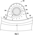
- FIG. 5 is an enlarged cross-sectional view of a pitch drive bracket 204 taken along line 5-5.
- the pitch assembly 200 includes a pitch bearing 202 and at least two pitch drive brackets 204.
- the pitch bearing 202 is rotatably coupled to the outer wall 158 of the hub 110, such that the pitch bearing 202 is rotatable about the pitch axis 118.
- the pitch bearing 202 includes an inner race 206 positioned radially inward to, and substantially concentric with, an outer race 208.
- the inner race 206 is rotatably coupled to the outer race 208 such that the inner race 206 rotates relative to the outer race 208 about the pitch axis 118.
- the outer race 208 is securely coupled to the outer wall 158 of the hub 110. More specifically, in an embodiment, the outer race 208 is coupled to the outer wall 158 of the hub 110 using a plurality of fasteners, such as bolts and nuts. Alternatively, the outer race 208 is coupled to the outer wall 158 of the hub 110 by methods that include, but are not limited to, retention hardware, welds, and/or sealing methods and apparatus known in the art.
- the outer race 208 is coupled to the outer wall 158 of the hub 110, such that the outer race 208 is in substantial contact with the bearing surface 164.
- an annular groove 210 is defined between the inner race 206 and the outer race 208 that includes at least one material 211 that facilitates reducing friction between inner race 206 and outer race 208.
- the material 211 is at least one of bearing balls, rollers, or a lubricant.
- the pitch assembly 200 may include a plurality of pitch drive brackets 204 positioned within the hub cavity 166. Further, as shown, the plurality of drive brackets 204 are coupled to the inner surface 160 of the hub 110. More specifically, in an embodiment, the pitch assembly 200 includes a first pitch drive bracket 212 and a second pitch drive bracket 214. In the illustrated embodiment, the first pitch drive bracket 212 is positioned substantially opposite the second pitch drive bracket 214 along a circumference 216 of the pitch bearing 202. In an alternative embodiment, the pitch assembly 200 includes a plurality of pitch drive brackets 204 that are equally spaced a circumferential distance D apart from each other about the pitch bearing 202. In another embodiment, the plurality of pitch drive brackets 204 are spaced at any distance that enables the pitch assembly 200 to function as described herein.
- the pitch drive brackets 204 are coupled to the inner surface 160 of the hub 110 using a weld, however, the pitch drive brackets 204 may be coupled to the inner surface 160 of the hub 110 by methods that include, but are not limited to, retention hardware, and sealing methods such that the pitch drive brackets 204 are securely coupled to the inner surface 160 of the hub 110.
- the pitch drive brackets 204 may be formed integral with the hub 110.
- One of the respective rotor blades 112 (shown in FIG. 1 ) is removably coupled to the inner race 206 using a plurality of bolts.
- the rotor blade 112 may be coupled to the inner race 206 using any methods known in the art that enable the rotor blade 112 to be removed from the inner race 206. It should be further understood that the rotor blade 112 may also be coupled to the outer race 208 using any methods known in the art that enable the rotor blade 112 to be removed from the outer race 208.
- the pitch assembly 200 also includes a pitch drive mechanism 220 that includes a pitch drive motor 222, a pitch gearbox 224, a pitch drive shaft 226 ( FIG. 4 ), and a primary pitch drive pinion 228.
- the pitch drive motor 222 is coupled to the pitch gearbox 224 such that the pitch drive motor 222 imparts mechanical force to the pitch gearbox 224.
- the pitch gearbox 224 is coupled to the pitch drive shaft 226 and the pitch drive shaft 226 is coupled to the primary pitch drive pinion 228, such that the primary pitch drive pinion 228 is rotated by the pitch gearbox 224, with the pitch drive shaft 226.
- one of the inner race 206 or the outer race 208 may include a plurality of gear teeth 207.
- the inner race 206 includes the plurality of gear teeth 207 spaced circumferentially about the inner race 206.
- the primary pitch drive pinion 228 engages a first set 250 of the gear teeth 207 to translate rotational force from the pitch drive mechanism 220 to the pitch bearing 202.
- the first set 250 of the gear teeth 207 engage the primary pitch drive pinion 228 such that the rotation of the primary pitch drive pinion 228 causes rotation of the inner race 206 of the pitch bearing 202.
- the first pitch drive bracket 212 is coupled to the pitch drive mechanism 220, such that the first pitch drive bracket 212 supports the pitch drive mechanism 220 and retains the pitch drive mechanism 220 in a fixed position relative to the pitch bearing 202. More specifically, the first pitch drive bracket 212 is sized to receive the pitch drive mechanism 220 therein.
- the first pitch drive bracket 212 is substantially similar to the second pitch drive bracket 214. More specifically, as shown in FIG. 4 , the first pitch drive bracket 212 may include a first member 230 and a second member 232.
- the first member 230 is coupled to the inner surface 160 of the hub 110 and extends substantially-radially inward from the inner surface 160. Further, the first member 230 includes a central opening 234 and a plurality of bores 236 ( FIG. 5 ).
- the central opening 234 is positioned substantially concentric within the first member 230 and extends at least partially therethrough.
- the central opening 234 is sized and shaped to receive the pitch drive shaft 226 and the primary pitch drive pinion 228.
- the primary pitch drive pinion 228 is rotatably coupled to the first member 230 and is positioned between the first member 230 and the pitch bearing 202.
- the primary pitch drive pinion 228 is inserted through the central opening 234 and is aligned concentric to the central opening 234.
- the central opening 234 is positioned a distance d1 from the inner surface 160 of the hub 110 such that the primary pitch drive pinion 228 contacts the gear teeth 207.
- the bores 236 are positioned radially outward from the central opening 234 and are aligned substantially circumferentially about the central opening 234.
- the second member 232 is coupled to the inner surface 160 of the hub 110 and extends substantially-radially inward from the inner surface 160 and is aligned substantially perpendicular thereto. Further, the second member 232 includes a central opening 238 and a plurality of bores 240, and is aligned to the first member 230, such that the central opening 234 of the first member 230 is concentrically aligned with the central opening 238 of the second member 232. Further, as shown in FIG. 4 , the second member 232 is positioned between the first member 230 and the pitch drive motor 222, such that the pitch drive shaft 226 is coupled to the first member 230 and the second member 232. Moreover, the central opening 238 is sized and shaped to receive the pitch drive shaft 226 and the pitch gearbox 224.
- the bores 240 of the second member 232 are circumferentially positioned about the central opening 238.
- the pitch gearbox 224 includes at least one opening 242 that is sized and shaped to receive at least one bolt 244.
- the bolt 244 is inserted through opening 242 and into a corresponding bore 240 to securely couple the pitch gearbox 224 to the second member 232, such that the first pitch drive bracket 212 facilitates reducing the pitch assembly 200 from moving relative to hub 110.
- the first member 230 and the second member 232 include a bell-shaped flange 246.
- first member 230 and second member 232 may have any shape that enables pitch assembly 200 to operate as described herein.
- the pitch drive mechanism 220 is coupled to the turbine control system 150 ( FIG. 2 ) for adjusting the pitch angle of the rotor blade(s) 112 upon receipt of a signal from the turbine control system 150.
- the pitch drive motor 222 includes any suitable structure, configuration, arrangement, means, and/or components, such as, but not limited to, electrical motors, hydraulic cylinders, springs, and/or servomechanisms.
- the pitch drive motor 222 is driven by any suitable means, such as, but not limited to, hydraulic fluid, electrical power, electro-chemical power, and/or mechanical power, such as, but not limited to, spring force.
- the pitch drive motor 222 is driven by energy extracted from at least one of a rotational inertia of the rotor 108 and a stored energy source (not shown) that supplies energy to components of the wind turbine 100.
- the pitch drive mechanism 220 uses the pitch drive motor 222 to change the pitch angle of the rotor blades 112 by rotating the rotor blades 112 with respect to the hub 110 and the outer race 208 (or inner race 206). More specifically, in an embodiment, the primary pitch drive pinion 228 is coupled to the pitch bearing 202 such that rotation of the pitch drive mechanism 220 rotates the pitch bearing 202 and the respective rotor blade 112 about the pitch axis 118 to change the pitch of the rotor blade 112. During operation of the wind turbine 100, the pitch drive mechanism 220 rotates each rotor blade 112 a limited distance about the pitch axis 118, such that the primary pitch drive pinion 228 contacts a limited number of gear teeth 207.
- the inner race 206 is securely coupled to the outer wall 158 of the hub 110 and is positioned in contact with the bearing surface 164.
- the outer race 208 is rotatably coupled to the inner race 206, such that the outer race 208 rotates relative to the inner race 206.
- the pitch drive brackets 204 are coupled to the outer surface 162 of the hub 110, such that the pitch drive mechanism 220 is positioned outside the hub cavity 166 and is coupled to the outer race 208.
- the rotor blade 112 is coupled to the outer race 208, such that the pitch drive mechanism 220 rotates the rotor blade 112 about the pitch axis 118.
- the pitch assembly 200 further includes a secondary pinion 254 engaging a second set 252 of the gear teeth 207 that is different than first set 250.
- the secondary pinion 254 is configured to rotate only when a torque at the secondary pinion 254 is exceeded by a torque threshold so as to minimize micro-pitching of the pitch assembly 200.
- backlash e.g., as indicated by a clearance 258 between gear teeth 260 of the primary pitch drive pinion 228 and the gear teeth 207
- backlash can cause micro-pitching, which causes damage to the pitch bearing 202.
- micro-movements cannot be eliminated by the turbine control system 150.
- the secondary pinion 254 is provided to address minimizing such micro-pitching.
- the secondary pinion 254 is mechanically coupled to a rotational device 262 for rotating the secondary pinion 254.
- the rotational device 262 may be a motor, a rachet mechanism, a spring mechanism, a crank, or a winch.
- the rotational device 262 is a rachet mechanism 264.
- the rachet mechanism 264 may include a two-way rachet mechanism. Still referring to FIG.
- the secondary pinion 254 is constructed of a deformable material 256.
- the deformable material 256 may be an elastomer material or a foam material.
- the deformable material 256 should be selected to still be stiff enough to prevent rotation of the pitch bearing 202.
- the primary pitch drive pinion 228 and the secondary pinion 254 are mounted to the hub 110 of the wind turbine 100.
- the primary pitch drive pinion 228 and the secondary pinion 254 may be mounted to the hub 110 via an attachment plate 266 secured to the hub 110. More specifically, as shown in FIG. 8B , the primary pitch drive pinion 228 and the secondary pinion 254 may each separate extend through an opening of a respective attachment plate 266 and the attachment plate(s) 266 may in turn be secured to the hub 110, e.g., via one or more fasteners 268.
- the attachment plate(s) 266 as described herein may be configured similar to the pitch drive brackets 204 described herein.
- the hub 110 may include one or more integral openings 270 configured to receive the primary pitch drive pinion 228 and the secondary pinion 254.
- the pitch assembly 200 may include a disengagement device 272 that disengages the secondary pinion 254 or overrides the torque threshold when commanded by a controller, such as turbine controller 150.
- the disengagement device 272 may include a clutch or a switch.
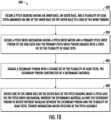
- FIG. 10 a flow diagram of an embodiment of a method 300 of minimizing micro-pitching of a pitch assembly of a wind turbine according to the present disclosure is illustrated.
- the method 300 will be described herein with reference to the pitch assembly illustrated in FIGS. 1-9 .
- the disclosed method 300 may be implemented with any pitch assembly having any other suitable configurations.
- FIG. 10 depicts steps performed in a particular order for purposes of illustration and discussion, the methods discussed herein are not limited to any particular order or arrangement.
- steps of the methods disclosed herein can be omitted, rearranged, combined, and/or adapted in numerous ways without deviating from the scope of the present disclosure.
- the method 300 includes securing a pitch bearing having an inner race, an outer race, and a plurality of gear teeth arranged on one of the inner race or the outer race to a hub of the wind turbine.
- the method 300 includes securing a pitch drive mechanism having a pitch drive motor and a primary pitch drive pinion to the hub such that the primary pitch drive pinion engages with a first set of the plurality of gear teeth.
- the method 300 includes engaging a secondary pinion with a second set of the plurality of gear teeth, the secondary pinion constructed of a deformable material.
- the method 300 includes rotating one of the inner race or the outer race of the pitch bearing about a pitch axis via the pitch drive mechanism, wherein the deformable material allows the secondary pinion to rotate without backlash between the secondary pinion and the plurality of gear teeth, thereby minimizing micro-pitching of the pitch assembly.
- the method 300 may include monitoring a torque at the secondary pinion and rotating the secondary pinion when the torque at the secondary pinion exceeds a torque threshold, which may correspond to a bearing starting torque.
- Exemplary embodiments of systems and methods of minimizing micro-pitching of a pitch assembly are described above in detail.
- the systems and methods are not limited to the specific embodiments described herein, but rather, components of systems and/or steps of the methods may be utilized independently and separately from other components and/or steps described herein.
- the methods may also be used in combination with other wind turbine and are not limited to practice with only the wind turbine generator as described herein. Rather, the various embodiments can be implemented and utilized in connection with many other wind turbine applications.
- a pitch assembly for a wind turbine comprising: a pitch bearing comprising an inner race, an outer race, and a plurality of gear teeth arranged on one of the inner race or the outer race; a pitch drive mechanism comprising a pitch drive motor and a primary pitch drive pinion, the primary pitch drive pinion configured to rotate one of the inner race or the outer race of the pitch bearing about a pitch axis by engaging with a first set of the plurality of gear teeth; and a secondary pinion engaging a second set of the plurality of gear teeth, the secondary pinion constructed of a deformable material such that backlash is eliminated between the secondary pinion and the plurality of gear teeth, thereby minimizing micro-pitching of the pitch assembly.
- the rotational device comprises at least one of a motor, a rachet mechanism, a spring mechanism, a crank, or a winch.
- the rotational device comprises the rachet mechanism
- the rachet mechanism comprises a two-way rachet mechanism.
- the deformable material comprises one of an elastomer material or a foam material.
- a method of minimizing micro-pitching of a pitch assembly of a wind turbine comprising: securing a pitch bearing having an inner race, an outer race, and a plurality of gear teeth arranged on one of the inner race or the outer race to a hub of the wind turbine; securing a pitch drive mechanism having a pitch drive motor and a primary pitch drive pinion to the hub such that the primary pitch drive pinion engages with a first set of the plurality of gear teeth; engaging a secondary pinion with a second set of the plurality of gear teeth, the secondary pinion constructed of a deformable material; and rotating one of the inner race or the outer race of the pitch bearing about a pitch axis via the pitch drive mechanism, wherein the deformable material allows the secondary pinion to rotate without backlash between the secondary pinion and the plurality of gear teeth, thereby minimizing micro-pitching of the pitch assembly.
- any preceding clause further comprising: monitoring a torque at the secondary pinion; and rotating the secondary pinion when the torque at the secondary pinion exceeds a torque threshold via a rotational device, wherein the rotational device comprises at least one of a motor, a rachet mechanism, a spring mechanism, a crank, or a winch.
- the deformable material comprises one of an elastomer material or a foam material.
- a pitch drive mechanism for a wind turbine comprising: a pitch drive motor; a primary pitch drive pinion configured to rotate one of an inner race or an outer race of a pitch bearing about a pitch axis by engaging with a first set of a plurality of gear teeth of one of the inner race or the outer race; and a secondary pinion configured to engage a second set of the plurality of gear teeth, the secondary pinion constructed of a deformable material such that backlash is eliminated between the secondary pinion and the plurality of gear teeth, thereby minimizing micro-pitching of the pitch assembly.
- the secondary pinion is configured to rotate only when a torque at the secondary pinion exceeds a torque threshold so as to minimize micro-pitching of the pitch drive mechanism.
- the pitch drive mechanism of any preceding clause further comprising a rotational device for rotating the secondary pinion, wherein the rotational device comprises at least one of a motor, a rachet mechanism, a spring mechanism, a crank, or a winch.
- the pitch drive mechanism of any preceding clause further comprising a disengagement device that disengages the secondary pinion or overrides the torque threshold when commanded by a controller.
- the deformable material comprises one of an elastomer material or a foam material.
- the pitch drive mechanism of any preceding clause further comprising an attachment plate secured to the hub, the secondary pinion being mounted to the hub of the wind turbine through the attachment plate.
Landscapes
- Engineering & Computer Science (AREA)
- General Engineering & Computer Science (AREA)
- Mechanical Engineering (AREA)
- Life Sciences & Earth Sciences (AREA)
- Sustainable Development (AREA)
- Sustainable Energy (AREA)
- Chemical & Material Sciences (AREA)
- Combustion & Propulsion (AREA)
- Physics & Mathematics (AREA)
- Fluid Mechanics (AREA)
- Electromagnetism (AREA)
- Thermal Sciences (AREA)
- Wind Motors (AREA)
Applications Claiming Priority (1)
| Application Number | Priority Date | Filing Date | Title |
|---|---|---|---|
| US18/519,433 US12276260B1 (en) | 2023-11-27 | 2023-11-27 | Pitch assembly for a wind turbine having minimized micro-pitching |
Publications (1)
| Publication Number | Publication Date |
|---|---|
| EP4560136A1 true EP4560136A1 (de) | 2025-05-28 |
Family
ID=93648503
Family Applications (1)
| Application Number | Title | Priority Date | Filing Date |
|---|---|---|---|
| EP24214569.6A Pending EP4560136A1 (de) | 2023-11-27 | 2024-11-21 | Pitchanordnung für eine windturbine mit minimiertem mikropitch |
Country Status (3)
| Country | Link |
|---|---|
| US (1) | US12276260B1 (de) |
| EP (1) | EP4560136A1 (de) |
| CN (1) | CN120042740A (de) |
Citations (2)
| Publication number | Priority date | Publication date | Assignee | Title |
|---|---|---|---|---|
| EP2597303A1 (de) * | 2011-11-24 | 2013-05-29 | Alstom Wind, S.L.U. | Windturbinenrotor |
| EP3786443A1 (de) * | 2019-08-30 | 2021-03-03 | General Electric Renovables España S.L. | Nabenanordnung für einen rotor einer windturbine |
Family Cites Families (5)
| Publication number | Priority date | Publication date | Assignee | Title |
|---|---|---|---|---|
| US4184380A (en) * | 1978-03-10 | 1980-01-22 | Rivin Evgeny I | Gears having resilient coatings |
| ATE327429T1 (de) * | 2002-04-26 | 2006-06-15 | Gen Electric | Vorrichtung zur einstellung einer rotorschaufel einer windenergieturbine |
| US7828686B2 (en) | 2009-03-19 | 2010-11-09 | General Electric Company | Yaw assembly for a rotatable system and method of assembling the same |
| EP2410175A1 (de) * | 2010-05-31 | 2012-01-25 | Mitsubishi Heavy Industries, Ltd. | Windturbinengenerator, ganggetriebemechanismus und verfahren zur steuerung des einlegens von gängen |
| GB201721214D0 (en) * | 2017-12-18 | 2018-01-31 | Romax Tech Limited | Pitch drive |
-
2023
- 2023-11-27 US US18/519,433 patent/US12276260B1/en active Active
-
2024
- 2024-11-21 EP EP24214569.6A patent/EP4560136A1/de active Pending
- 2024-11-25 CN CN202411690029.7A patent/CN120042740A/zh active Pending
Patent Citations (2)
| Publication number | Priority date | Publication date | Assignee | Title |
|---|---|---|---|---|
| EP2597303A1 (de) * | 2011-11-24 | 2013-05-29 | Alstom Wind, S.L.U. | Windturbinenrotor |
| EP3786443A1 (de) * | 2019-08-30 | 2021-03-03 | General Electric Renovables España S.L. | Nabenanordnung für einen rotor einer windturbine |
Also Published As
| Publication number | Publication date |
|---|---|
| CN120042740A (zh) | 2025-05-27 |
| US12276260B1 (en) | 2025-04-15 |
Similar Documents
| Publication | Publication Date | Title |
|---|---|---|
| US8092171B2 (en) | Systems and methods for assembling a pitch assembly for use in a wind turbine | |
| US20100143136A1 (en) | Systems and methods for assembling a pitch assembly for use in a wind turbine | |
| US20110135481A1 (en) | Systems and methods for assembling a rotor lock assembly for use in a wind turbine | |
| US9041237B2 (en) | Wind turbine drive train and wind turbine | |
| US20110140439A1 (en) | Yaw assembly for use in wind turbines | |
| US8091199B2 (en) | Method to repair pitch control components | |
| EP2354545A1 (de) | Systeme und Verfahren zur Montage einer Bohrlochreparaturanordnung zur Verwendung in einer Windturbine | |
| US10502193B2 (en) | Repair method for a gearbox assembly of a wind turbine | |
| EP3428449B1 (de) | Antriebsstrang für eine windkraftanlage und verfahren zur positionierung eines hauptlagers des antriebsstrangs | |
| EP3530939A1 (de) | Ersatzverfahren für radialdichtungen von windturbinenhauptlagern | |
| US11965479B2 (en) | System and method for repairing a gearbox of a wind turbine uptower | |
| US20140064971A1 (en) | Stiffener plate for a wind turbine | |
| EP4357613A1 (de) | Antriebsstranganordnungen für windturbinen | |
| EP4102065B1 (de) | Nabe-welle-bolzenverbindung einer windturbine | |
| US12276260B1 (en) | Pitch assembly for a wind turbine having minimized micro-pitching | |
| US10502195B2 (en) | Clamping apparatus for securing a main bearing of a wind turbine during an installation and/or repair procedure | |
| WO2019212557A1 (en) | Pitch bearing for a wind turbine | |
| EP3872337B1 (de) | Gierbremsanordnung einer windturbine | |
| EP4438889A1 (de) | Nabenanordnung für eine windturbine mit einem abstandshalter | |
| WO2026037498A1 (en) | Method for reparing a journal bearing assembly and journal bearing assembly of a wind turbine |
Legal Events
| Date | Code | Title | Description |
|---|---|---|---|
| PUAI | Public reference made under article 153(3) epc to a published international application that has entered the european phase |
Free format text: ORIGINAL CODE: 0009012 |
|
| STAA | Information on the status of an ep patent application or granted ep patent |
Free format text: STATUS: THE APPLICATION HAS BEEN PUBLISHED |
|
| AK | Designated contracting states |
Kind code of ref document: A1 Designated state(s): AL AT BE BG CH CY CZ DE DK EE ES FI FR GB GR HR HU IE IS IT LI LT LU LV MC ME MK MT NL NO PL PT RO RS SE SI SK SM TR |
|
| STAA | Information on the status of an ep patent application or granted ep patent |
Free format text: STATUS: REQUEST FOR EXAMINATION WAS MADE |
|
| GRAJ | Information related to disapproval of communication of intention to grant by the applicant or resumption of examination proceedings by the epo deleted |
Free format text: ORIGINAL CODE: EPIDOSDIGR1 |
|
| GRAP | Despatch of communication of intention to grant a patent |
Free format text: ORIGINAL CODE: EPIDOSNIGR1 |
|
| 17P | Request for examination filed |
Effective date: 20251107 |
|
| GRAP | Despatch of communication of intention to grant a patent |
Free format text: ORIGINAL CODE: EPIDOSNIGR1 |
|
| STAA | Information on the status of an ep patent application or granted ep patent |
Free format text: STATUS: GRANT OF PATENT IS INTENDED |
|
| RAP3 | Party data changed (applicant data changed or rights of an application transferred) |
Owner name: GENERAL ELECTRIC RENOVABLES ESPANA S.L. |
|
| INTG | Intention to grant announced |
Effective date: 20260107 |
|
| GRAJ | Information related to disapproval of communication of intention to grant by the applicant or resumption of examination proceedings by the epo deleted |
Free format text: ORIGINAL CODE: EPIDOSDIGR1 |
|
| STAA | Information on the status of an ep patent application or granted ep patent |
Free format text: STATUS: REQUEST FOR EXAMINATION WAS MADE |