EP4560152A1 - Ancrage à expansion avec bord de transition de paroi de butée en biais - Google Patents
Ancrage à expansion avec bord de transition de paroi de butée en biais Download PDFInfo
- Publication number
- EP4560152A1 EP4560152A1 EP23211232.6A EP23211232A EP4560152A1 EP 4560152 A1 EP4560152 A1 EP 4560152A1 EP 23211232 A EP23211232 A EP 23211232A EP 4560152 A1 EP4560152 A1 EP 4560152A1
- Authority
- EP
- European Patent Office
- Prior art keywords
- expansion
- sleeve
- abutment wall
- transition edge
- anchor bolt
- Prior art date
- Legal status (The legal status is an assumption and is not a legal conclusion. Google has not performed a legal analysis and makes no representation as to the accuracy of the status listed.)
- Pending
Links
Images

Classifications
-
- F—MECHANICAL ENGINEERING; LIGHTING; HEATING; WEAPONS; BLASTING
- F16—ENGINEERING ELEMENTS AND UNITS; GENERAL MEASURES FOR PRODUCING AND MAINTAINING EFFECTIVE FUNCTIONING OF MACHINES OR INSTALLATIONS; THERMAL INSULATION IN GENERAL
- F16B—DEVICES FOR FASTENING OR SECURING CONSTRUCTIONAL ELEMENTS OR MACHINE PARTS TOGETHER, e.g. NAILS, BOLTS, CIRCLIPS, CLAMPS, CLIPS OR WEDGES; JOINTS OR JOINTING
- F16B13/00—Dowels or other devices fastened in walls or the like by inserting them in holes made therein for that purpose
- F16B13/04—Dowels or other devices fastened in walls or the like by inserting them in holes made therein for that purpose with parts gripping in the hole or behind the reverse side of the wall after inserting from the front
- F16B13/06—Dowels or other devices fastened in walls or the like by inserting them in holes made therein for that purpose with parts gripping in the hole or behind the reverse side of the wall after inserting from the front combined with expanding sleeve
- F16B13/063—Dowels or other devices fastened in walls or the like by inserting them in holes made therein for that purpose with parts gripping in the hole or behind the reverse side of the wall after inserting from the front combined with expanding sleeve by the use of an expander
- F16B13/065—Dowels or other devices fastened in walls or the like by inserting them in holes made therein for that purpose with parts gripping in the hole or behind the reverse side of the wall after inserting from the front combined with expanding sleeve by the use of an expander fastened by extracting the screw, nail or the like
Definitions
- the invention relates to an expansion anchor according to the preamble of claim 1.
- US2021231150 A1 and US2020224695 A1 describe expansion anchors provided with sleeve abutment walls on their expansion bodies.
- the sleeve abutment walls are formed at abutment wall recesses which are provided within the respective expansion bodies.
- the sleeve abutment walls are intended to be hit by the respective expansion sleeves when the anchors are expanded.
- EP4074991 A1 and EP4074990 A1 show expansion anchors with related geometries.
- the invention is based on providing the expansion body with a sleeve abutment wall, which sleeve abutment wall faces the expansion sleeve before installation of the anchor, so that the expansion sleeve can hit the sleeve abutment wall when the expansion body moves along the expansion sleeve during expansion of the expansion sleeve, when the anchor is installed.
- this can advantageously modulate the anchoring process.
- the invention now proposes to arrange the transition edge that is formed between the recess floor and the sleeve abutment wall, and which forms the root of the sleeve abutment wall, in a non-perpendicular relationship with respect to the longitudinal axis of the anchor bolt. More particularly, the transition edge extends at lead angle ⁇ that is greater than or equal to 4° and smaller than or equal to 30°, at least in a section of the transition edge, preferably throughout the transition edge.
- the angle Due to this angled arrangement of the transition edge, a progressive axial abutment and/or gradual increase of internal resistance, which may in term be beneficial for anchoring performance, can be achieved with particularly low manufacturing effort.
- the angle has an upper limit, which provides significant abutment area without the need for overly large dimensions, further reducing the effort.
- the lead angle ⁇ 4 ° ⁇ ⁇ ⁇ 30 ° , or 4 ° ⁇ ⁇ ⁇ 16 ° , or 9° ⁇ ⁇ ⁇ 11°.
- the entirety of the transition edge is within the described range.
- the lead angle ⁇ , at which the transition edge extends can be generally constant throughout the transition edge. All of this can provide for particularly homogenous operation.
- the anchor bolt is an elongate body.
- the expansion body and the anchor bolt are, in particular, connected to transfer tensile forces in the axial direction.
- the expansion body can for example be threaded to the anchor bolt, in particular if the expansion anchor is a so-called sleeve-type expansion anchor.
- the expansion body can also be tightly fixed to the anchor bolt, in particular if the expansion anchor is a so-called stud-type expansion anchor. It is particularly preferred in case of a stud-type expansion anchor that the expansion body and the anchor bolt are monolithic, i.e. that they form one piece.
- the anchor bolt is preferably provided with a forwardly facing shoulder for expansion sleeve abutment and for advancing the expansion sleeve into the borehole.
- the expansion body is a part of the expansion anchor.
- the expansion sleeve surrounds the anchor bolt, in particular around the longitudinal axis.
- the expansion sleeve is a single piece. However, it could also consist of several individual segments, which are for example held in an anchor bolt-surrounding arrangement by means of a rubber band or by snap-on mechanisms.
- the anchor bolt, the expansion sleeve and/or the expansion body are each steel parts. They can for example comprise carbon steel or stainless steel.
- the front region of the anchor bolt, in which the expansion body is located, is that region that is intended to lead when the expansion anchor is inserted into a borehole.
- the longitudinal axis of the anchor bolt extends through the front region and through the rear region of the anchor bolt.
- the anchor bolt can have, in a rear region of the anchor bolt, a tension-introducing structure.
- the tension-introducing structure is for introducing tensile force into the anchor bolt.
- the tension-introducing structure can for example be a thread, in particular an outer thread, provided on the anchor bolt.
- the tension-introducing structure could for example also be a head, which forms a maximum cross-section, or a bayonet-type lock.
- the converging zone of the expansion body serves to expand the expansion sleeve when the expansion sleeve is moved forward with respect to the expansion body, in particular to expand the expansion sleeve radially with respect to the longitudinal axis.
- the expansion body converges on its lateral surface, towards the rear of the anchor bolt and/or towards the tension-introducing structure, wherein the focus of convergence can preferably be the longitudinal axis. This in particular implies that the radial distance of the lateral surface of the expansion body from the longitudinal axis becomes smaller towards the rear of the expansion body.
- the expansion body can have additional zones, for example a preferably cylindrical transition zone and/or a tip zone.
- the converging zone can for example be conical, or can have a more complex, for example a convex or concave shape. In particular, the converging zone forms a wedge for the expansion sleeve.
- the sleeve abutment wall is so arranged that the expansion sleeve can hit the sleeve abutment wall, i.e. that the expansion sleeve can abut on the sleeve abutment wall, when the expansion sleeve is axially displaced relative to the expansion body in the forwards direction, i.e. towards the front end of the expansion body and/or the anchor bolt, in particular by drawing-in the expansion body into the expansion sleeve in the rearwards direction.
- the sleeve abutment wall axially faces the expansion sleeve, or, in other words, the sleeve abutment wall faces the expansion sleeve in a direction parallel to the longitudinal axis.
- the sleeve abutment wall axially faces the tip of the expansion sleeve and/or serves for abutment of the tip of the expansion sleeve, and can therefore be named expansion sleeve tip abutment wall.
- the tip of the expansion sleeve can be understood to be the front end of the expansion sleeve, i.e. the end pointing in the forwards direction.
- the sleeve abutment wall is arranged vis-à-vis, in particularly axially vis-à-vis, the expansion sleeve, and particularly the tip of the expansion sleeve.
- the sleeve abutment wall axially faces the expansion sleeve, in particular the expansion sleeve tip, in a state before the expansion sleeve is expanded by the expansion body, i.e. in the pre-installation state of the anchor, before the anchor is installed.
- the sleeve abutment wall faces towards the rear of the anchor.
- the anchor is so configured that the expansion sleeve, in particular with its tip, can hit the sleeve abutment wall during axial displacement of the expansion body relative to the expansion sleeve in the rearwards direction and/or during radial expansion of the expansion sleeve by the expansion body.
- the sleeve abutment wall is suitable and/or configured for being abutted on by the expansion sleeve, in particular axially and/or by the tip of the expansion sleeve.
- the sleeve abutment wall projects radially on the expansion body and/or a step structure is formed at the sleeve abutment wall, wherein the sleeve abutment wall forms the riser of the respective step structure.
- the sleeve abutment wall is arranged on the lateral surface of the expansion body, i.e. on the side of the expansion body.
- the expansion body is provided, in particular on its lateral surface, with an abutment wall recess, wherein the abutment wall recess is axially delimited, in particular at its front end, by the sleeve abutment wall.
- the sleeve abutment wall forms the front-end wall of the abutment wall recess.
- the abutment wall recess extends radially into the expansion body.
- the abutment wall recess is preferably at least partly located in the converging zone of the expansion body.
- the recess floor forms a further wall of the abutment wall recess and/or radially delimits the abutment wall recess.
- the recess floor and the sleeve abutment wall meet geometrically, and the transition edge is formed where the recess floor and the sleeve abutment wall meet.
- both the recess floor and the sleeve abutment wall adjoin the transition edge.
- the transition edge is located within the abutment wall recess.
- the lead angle is the lead angle with respect to the longitudinal axis.
- the lead angle can be considered to be the angle between a tangent on the transition edge and a plane that is orientated perpendicular to the longitudinal axis.
- the term “longitudinal axis” should, in particular, refer to the longitudinal axis of the anchor bolt, which may usually coincide with the longitudinal axis of the expansion anchor.
- the "longitudinal axis” can in particular be the axis that runs in the longitudinal direction, i.e. in the long direction of the elongate anchor bolt.
- the terms “radially”, “axially” or “circumferentially” are used, this should in particular be understood with respect to the longitudinal axis of the anchor bolt.
- the least one sleeve abutment wall tapers towards the rear of the anchor bolt.
- the sleeve abutment wall is, at least in total, non-perpendicular to the longitudinal axis. Rather, the radius of the expansion body gradual decreases towards the rear of the anchor bolt at the sleeve abutment wall. This allows creating a surmountable obstruction in a particularly reliable and easy-to-manufacture way.
- the expansion body can have, located in front of the converging zone, a transition zone.
- a transition zone In such a transition zone, the convergence of the expansion body is at least less steep as compared with the converging zone, or the convergence can be completely absent.
- Such a transition zone can prevent over-expanding the expansion sleeve and over-stressing the surrounding substrate at high loads. If convergence is completely absent, the transition zone can have a cylindrical lateral surface, wherein cylindrical is to be understood in a broad definition, in which the cylinder base can be, but does not necessarily have to be circular.
- the sleeve abutment wall and/or the transition edge is preferably located within the converging zone, at least partly, preferably completely. If a transition zone is present, the sleeve abutment wall and/or the transition edge can also reach into this transition zone.
- the expansion body has at least one additional abutment wall recess, preferably two or three of them.
- the at least one additional abutment wall recess has preferably generally the same shape and/or function as the abutment wall recess.
- the abutment wall recess and the at least one additional abutment wall recess are preferably arranged abreast, i.e. at same axial orientation.
- the expansion body might be provided with additional walls, e.g. recess side walls, which additional walls do not axially face the expansion sleeve and/or which additional walls are not suitable for expansion sleeve abutment upon axial displacement of the expansion sleeve, and which therefore cannot be termed sleeve abutment walls.
- additional walls e.g. recess side walls, which additional walls do not axially face the expansion sleeve and/or which additional walls are not suitable for expansion sleeve abutment upon axial displacement of the expansion sleeve, and which therefore cannot be termed sleeve abutment walls.
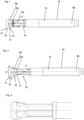
- the figures show an embodiment of an expansion anchor.
- the anchor comprises an elongate anchor bolt 10 having a front end (left end in figure 2 ) and a rear end (right end in figure 2 ), an expansion sleeve 30, which surrounds the anchor bolt 10, and an expansion body 12 for radially expanding the expansion sleeve 30 and provided on the anchor bolt 10, namely in the vicinity of the front end of the anchor bolt 10.
- the anchor bolt 10 has a longitudinal axis 99, which extends through the front end and through the rear end of the anchor bolt 10. The longitudinal axis 99 passes through the expansion sleeve 30.
- the expansion body 12 has a converging zone 23 designed for radially expanding the expansion sleeve 30 when the expansion body 12 is drawn into the expansion sleeve 30 in the rearward direction, i.e. when the expansion sleeve 30 moves forwards relative to the expansion body 12 onto the expansion body 12.
- the lateral surface of the expansion body 12 converges towards the rear end of the anchor bolt 10, i.e. it converges towards the expansion sleeve 30, at least before the anchor is installed.
- the lateral surface of the expansion body 12 is conical in the converging zone 23, with a focus of convergence on the longitudinal axis 99 and with apex angle ⁇ shown in figure 2 .
- this is merely an example and other converging designs are also possible.
- the expansion body 12 also has a transition zone 22, which is located forwards of and adjacent to the converging zone 23, and a tip zone 21, which is located forwards of and adjacent to the transition zone 22.
- the rearward convergence is smaller as compared to the converging zone 23 or the rearward convergence is even zero, but preferably not reverse, i.e. it is not a forward convergence.
- convergence is absent, i.e. zero, in the converging zone 23 and the expansion body 12 has a cylindrical lateral surface in the converging zone 23, in particular cylindrical with a circular base.
- the tip zone 21 the lateral surface of the expansion body 12 converges towards the front end of the anchor.
- the anchor bolt 10 has a neck 25, which is located adjacent to and rearwards of the expansion body 12.
- the expansion sleeve 30 at least partly surrounds this neck 25, at least before installation the anchor.
- the diameter of the anchor bolt 10 can be minimal.
- the anchor bolt 10 is provided, within its the neck 25, with a plurality of axially extending grooves, and the expansion sleeve 30 is provided with corresponding axially extending ridges that engage the axially extending grooves, but this is an example only.
- the anchor is of the stud type.
- the anchor bolt 10 has, namely at the rearward end of the neck 25, a shoulder 17 facing forwards for axially engaging the expansion sleeve 30 and for advancing the expansion sleeve 30 forwards.
- the expansion body 12 and the anchor bolt 10 are, by way of example, monolithic, but this is an example only, and non-monolithic designs are also feasible.
- the anchor bolt 10 is provided with a tension-introducing structure 18, here in the form of an outer thread provided on the anchor bolt 10.
- the expansion sleeve 30 is provided with a plurality of slits 36' (four in the present case, by way of example, of which only a single one is visible in figure 1 ), which originate from the front end of the expansion sleeve 30 and extend towards the rear end of the expansion sleeve 30.
- an abutment wall recess 66 On the lateral surface of the expansion body 12 is provided an abutment wall recess 66, which provides a depression within the expansion body 12 and which is radially accessible from the outside of the expansion body 12.
- the abutment wall recess extends 66 at least within the converging zone 23 of the expansion body 12. In the present embodiment, the abutment wall recess 66 extends only within the expansion body 12, but in other embodiments, it might also extend into the neck 25.
- the abutment wall recess 66 is, radially, delimited by a recess floor 62. At its front end, the abutment wall recess 66 is, axially, delimited by a sleeve abutment wall 60.
- the sleeve abutment wall 60 axially faces the expansion sleeve 30, i.e. it faces rearwardly.
- the sleeve abutment wall 60 could be arranged perpendicularly to the longitudinal axis 99, but in the shown embodiment, the sleeve abutment wall 60 and the longitudinal axis 99 converge towards the rear end of the anchor bolt 10.
- the sleeve abutment wall 60 forms a, preferably surmountable, abutment for the front end, i.e. for the tip of the expansion sleeve 30.
- the expansion sleeve 30 is intended to abut against the sleeve abutment wall 60 when the expansion body 12 is drawn into the expansion sleeve 30 causing the expansion sleeve 30 to be displaced forwardly relative to the expansion body 12.
- a transition edge 69 is formed.
- the transition edge 69 adjoins both the recess floor 62 and the sleeve abutment wall 60.
- the transition edge 69 is arranged at a lead angle ⁇ , particular with respect to a plane 91 that is arranged perpendicular to the longitudinal axis 99.
- This lead angle ⁇ is generally constant all along the transition edge 69. In the present embodiment, it is approximately 10°.
- the expansion body 12 is provided with at least one additional abutment wall recess (three additional abutment wall recesses in the present embodiment, by way of example, of which only a two, denoted with 66' and 66′′′, respectively, are visible in the drawings).
- Each of these additional abutment wall recesses 66', 66′′′ has a shape that is generally the same as the shape of the abutment wall recess 66.
- each of these additional abutment wall recesses 66', 66′′′ is radially delimited by an additional recess floor, and at its respective front end, each of the additional abutment wall recesses is, axially, delimited by an additional sleeve abutment wall, which faces the expansion sleeve, i.e. it faces rearwardly.
- an additional transition edge is formed.
- the at least one additional sleeve abutment wall and the sleeve abutment wall 60 are located abreast, located at the same position along the longitudinal axis 99, and do not overlap in the circumferential direction.
- the anchor can be installed as follows: In a first step the anchor is introduced, front end first, into a hole in a substrate.
- the expansion body 12 is drawn into the front-end region of the expansion sleeve 30, which means that the expansion sleeve 30 is displaced forwards relative to the expansion body 12 and over the expansion body 12.
- this is achieved by pulling the anchor bolt 10 together with the expansion body 12 rearwardly, in particular by tightening a non-shown nut provided on the tension-introducing structure 18 of the anchor bolt 10.
- Drawing-in of the expansion body 12 into the expansion sleeve 30 causes the expansion sleeve 30 to expand radially, thereby locking the anchor in the substrate.
Landscapes
- Engineering & Computer Science (AREA)
- General Engineering & Computer Science (AREA)
- Mechanical Engineering (AREA)
- Dowels (AREA)
Priority Applications (3)
| Application Number | Priority Date | Filing Date | Title |
|---|---|---|---|
| EP23211232.6A EP4560152A1 (fr) | 2023-11-21 | 2023-11-21 | Ancrage à expansion avec bord de transition de paroi de butée en biais |
| PCT/EP2024/081609 WO2025108724A1 (fr) | 2023-11-21 | 2024-11-08 | Ancrage à expansion avec bord de transition de paroi de butée incliné |
| CN202480063077.5A CN121941854A (zh) | 2023-11-21 | 2024-11-08 | 具有成角度的抵接壁过渡边缘的膨胀锚 |
Applications Claiming Priority (1)
| Application Number | Priority Date | Filing Date | Title |
|---|---|---|---|
| EP23211232.6A EP4560152A1 (fr) | 2023-11-21 | 2023-11-21 | Ancrage à expansion avec bord de transition de paroi de butée en biais |
Publications (1)
| Publication Number | Publication Date |
|---|---|
| EP4560152A1 true EP4560152A1 (fr) | 2025-05-28 |
Family
ID=88923627
Family Applications (1)
| Application Number | Title | Priority Date | Filing Date |
|---|---|---|---|
| EP23211232.6A Pending EP4560152A1 (fr) | 2023-11-21 | 2023-11-21 | Ancrage à expansion avec bord de transition de paroi de butée en biais |
Country Status (3)
| Country | Link |
|---|---|
| EP (1) | EP4560152A1 (fr) |
| CN (1) | CN121941854A (fr) |
| WO (1) | WO2025108724A1 (fr) |
Citations (4)
| Publication number | Priority date | Publication date | Assignee | Title |
|---|---|---|---|---|
| US20200224695A1 (en) | 2017-10-25 | 2020-07-16 | Hilti Aktiengesellschaft | Expansion anchor with sleeve abutment walls |
| US20210231150A1 (en) | 2018-06-20 | 2021-07-29 | Hilti Aktiengesellschaft | Expansion anchor with a nonaxisymmetric recess |
| EP4074991A1 (fr) | 2021-04-13 | 2022-10-19 | Hilti Aktiengesellschaft | Ancrage d'expansion |
| EP4074990A1 (fr) | 2021-04-13 | 2022-10-19 | Hilti Aktiengesellschaft | Ancrage d'expansion |
-
2023
- 2023-11-21 EP EP23211232.6A patent/EP4560152A1/fr active Pending
-
2024
- 2024-11-08 CN CN202480063077.5A patent/CN121941854A/zh active Pending
- 2024-11-08 WO PCT/EP2024/081609 patent/WO2025108724A1/fr active Pending
Patent Citations (4)
| Publication number | Priority date | Publication date | Assignee | Title |
|---|---|---|---|---|
| US20200224695A1 (en) | 2017-10-25 | 2020-07-16 | Hilti Aktiengesellschaft | Expansion anchor with sleeve abutment walls |
| US20210231150A1 (en) | 2018-06-20 | 2021-07-29 | Hilti Aktiengesellschaft | Expansion anchor with a nonaxisymmetric recess |
| EP4074991A1 (fr) | 2021-04-13 | 2022-10-19 | Hilti Aktiengesellschaft | Ancrage d'expansion |
| EP4074990A1 (fr) | 2021-04-13 | 2022-10-19 | Hilti Aktiengesellschaft | Ancrage d'expansion |
Also Published As
| Publication number | Publication date |
|---|---|
| WO2025108724A1 (fr) | 2025-05-30 |
| CN121941854A (zh) | 2026-04-28 |
Similar Documents
| Publication | Publication Date | Title |
|---|---|---|
| CN111033060B (zh) | 具有套筒抵接壁的膨胀锚 | |
| EP3810940B1 (fr) | Cheville à expansion comprenant un évidement non axisymétrique | |
| EP4560152A1 (fr) | Ancrage à expansion avec bord de transition de paroi de butée en biais | |
| EP3864304B1 (fr) | Cheville à expansion comportant un boulon d'ancrage rainuré | |
| EP3864306B1 (fr) | Cheville à expansion comprenant une zone renflée | |
| EP3864305B1 (fr) | Cheville à expansion comprenant des rainures vers le avant et vers l'arrière | |
| EP4323656B1 (fr) | Ancrage d'expansion | |
| EP4074991A1 (fr) | Ancrage d'expansion | |
| HK40101733A (en) | Expansion anchor | |
| HK40101733B (en) | Expansion anchor | |
| EP4692572A1 (fr) | Ancre extensible avec manchon de support de cisaillement | |
| HK40040508A (en) | Expansion anchor with a nonaxisymmetric recess | |
| HK40040508B (en) | Expansion anchor with a nonaxisymmetric recess | |
| HK40026619A (en) | Expansion anchor with sleeve abutment walls | |
| HK40026619B (en) | Expansion anchor with sleeve abutment walls |
Legal Events
| Date | Code | Title | Description |
|---|---|---|---|
| PUAI | Public reference made under article 153(3) epc to a published international application that has entered the european phase |
Free format text: ORIGINAL CODE: 0009012 |
|
| STAA | Information on the status of an ep patent application or granted ep patent |
Free format text: STATUS: THE APPLICATION HAS BEEN PUBLISHED |
|
| AK | Designated contracting states |
Kind code of ref document: A1 Designated state(s): AL AT BE BG CH CY CZ DE DK EE ES FI FR GB GR HR HU IE IS IT LI LT LU LV MC ME MK MT NL NO PL PT RO RS SE SI SK SM TR |
|
| STAA | Information on the status of an ep patent application or granted ep patent |
Free format text: STATUS: THE APPLICATION IS DEEMED TO BE WITHDRAWN |