EP4560201A1 - Appareil ménager avec élément de fermeture mobile - Google Patents
Appareil ménager avec élément de fermeture mobile Download PDFInfo
- Publication number
- EP4560201A1 EP4560201A1 EP24209402.7A EP24209402A EP4560201A1 EP 4560201 A1 EP4560201 A1 EP 4560201A1 EP 24209402 A EP24209402 A EP 24209402A EP 4560201 A1 EP4560201 A1 EP 4560201A1
- Authority
- EP
- European Patent Office
- Prior art keywords
- kinematics
- household appliance
- designed
- closure element
- drive unit
- Prior art date
- Legal status (The legal status is an assumption and is not a legal conclusion. Google has not performed a legal analysis and makes no representation as to the accuracy of the status listed.)
- Pending
Links
Images


Classifications
-
- F—MECHANICAL ENGINEERING; LIGHTING; HEATING; WEAPONS; BLASTING
- F24—HEATING; RANGES; VENTILATING
- F24C—DOMESTIC STOVES OR RANGES ; DETAILS OF DOMESTIC STOVES OR RANGES, OF GENERAL APPLICATION
- F24C15/00—Details
- F24C15/02—Doors specially adapted for stoves or ranges
- F24C15/023—Mounting of doors, e.g. hinges, counterbalancing
-
- A—HUMAN NECESSITIES
- A47—FURNITURE; DOMESTIC ARTICLES OR APPLIANCES; COFFEE MILLS; SPICE MILLS; SUCTION CLEANERS IN GENERAL
- A47L—DOMESTIC WASHING OR CLEANING; SUCTION CLEANERS IN GENERAL
- A47L15/00—Washing or rinsing machines for crockery or tableware
- A47L15/42—Details
- A47L15/4251—Details of the casing
- A47L15/4257—Details of the loading door
- A47L15/4261—Connections of the door to the casing, e.g. door hinges
-
- E—FIXED CONSTRUCTIONS
- E05—LOCKS; KEYS; WINDOW OR DOOR FITTINGS; SAFES
- E05F—DEVICES FOR MOVING WINGS INTO OPEN OR CLOSED POSITION; CHECKS FOR WINGS; WING FITTINGS NOT OTHERWISE PROVIDED FOR, CONCERNED WITH THE FUNCTIONING OF THE WING
- E05F15/00—Power-operated mechanisms for wings
- E05F15/60—Power-operated mechanisms for wings using electrical actuators
- E05F15/603—Power-operated mechanisms for wings using electrical actuators using rotary electromotors
- E05F15/611—Power-operated mechanisms for wings using electrical actuators using rotary electromotors for swinging wings
- E05F15/63—Power-operated mechanisms for wings using electrical actuators using rotary electromotors for swinging wings operated by swinging arms
-
- E—FIXED CONSTRUCTIONS
- E05—LOCKS; KEYS; WINDOW OR DOOR FITTINGS; SAFES
- E05F—DEVICES FOR MOVING WINGS INTO OPEN OR CLOSED POSITION; CHECKS FOR WINGS; WING FITTINGS NOT OTHERWISE PROVIDED FOR, CONCERNED WITH THE FUNCTIONING OF THE WING
- E05F1/00—Closers or openers for wings, not otherwise provided for in this subclass
- E05F1/08—Closers or openers for wings, not otherwise provided for in this subclass spring-actuated, e.g. for horizontally sliding wings
- E05F1/10—Closers or openers for wings, not otherwise provided for in this subclass spring-actuated, e.g. for horizontally sliding wings for swinging wings, e.g. counterbalance
- E05F1/12—Mechanisms in the shape of hinges or pivots, operated by springs
- E05F1/1246—Mechanisms in the shape of hinges or pivots, operated by springs with a coil spring perpendicular to the pivot axis
- E05F1/1253—Mechanisms in the shape of hinges or pivots, operated by springs with a coil spring perpendicular to the pivot axis with a compression spring
- E05F1/1261—Mechanisms in the shape of hinges or pivots, operated by springs with a coil spring perpendicular to the pivot axis with a compression spring for counterbalancing
-
- E—FIXED CONSTRUCTIONS
- E05—LOCKS; KEYS; WINDOW OR DOOR FITTINGS; SAFES
- E05Y—INDEXING SCHEME ASSOCIATED WITH SUBCLASSES E05D AND E05F, RELATING TO CONSTRUCTION ELEMENTS, ELECTRIC CONTROL, POWER SUPPLY, POWER SIGNAL OR TRANSMISSION, USER INTERFACES, MOUNTING OR COUPLING, DETAILS, ACCESSORIES, AUXILIARY OPERATIONS NOT OTHERWISE PROVIDED FOR, APPLICATION THEREOF
- E05Y2201/00—Constructional elements; Accessories therefor
- E05Y2201/60—Suspension or transmission members; Accessories therefor
- E05Y2201/622—Suspension or transmission members elements
- E05Y2201/624—Arms
- E05Y2201/626—Levers
-
- E—FIXED CONSTRUCTIONS
- E05—LOCKS; KEYS; WINDOW OR DOOR FITTINGS; SAFES
- E05Y—INDEXING SCHEME ASSOCIATED WITH SUBCLASSES E05D AND E05F, RELATING TO CONSTRUCTION ELEMENTS, ELECTRIC CONTROL, POWER SUPPLY, POWER SIGNAL OR TRANSMISSION, USER INTERFACES, MOUNTING OR COUPLING, DETAILS, ACCESSORIES, AUXILIARY OPERATIONS NOT OTHERWISE PROVIDED FOR, APPLICATION THEREOF
- E05Y2600/00—Mounting or coupling arrangements for elements provided for in this subclass
- E05Y2600/10—Adjustable
- E05Y2600/12—Adjustable by manual operation
-
- E—FIXED CONSTRUCTIONS
- E05—LOCKS; KEYS; WINDOW OR DOOR FITTINGS; SAFES
- E05Y—INDEXING SCHEME ASSOCIATED WITH SUBCLASSES E05D AND E05F, RELATING TO CONSTRUCTION ELEMENTS, ELECTRIC CONTROL, POWER SUPPLY, POWER SIGNAL OR TRANSMISSION, USER INTERFACES, MOUNTING OR COUPLING, DETAILS, ACCESSORIES, AUXILIARY OPERATIONS NOT OTHERWISE PROVIDED FOR, APPLICATION THEREOF
- E05Y2600/00—Mounting or coupling arrangements for elements provided for in this subclass
- E05Y2600/50—Mounting methods; Positioning
- E05Y2600/51—Screwing or bolting
-
- E—FIXED CONSTRUCTIONS
- E05—LOCKS; KEYS; WINDOW OR DOOR FITTINGS; SAFES
- E05Y—INDEXING SCHEME ASSOCIATED WITH SUBCLASSES E05D AND E05F, RELATING TO CONSTRUCTION ELEMENTS, ELECTRIC CONTROL, POWER SUPPLY, POWER SIGNAL OR TRANSMISSION, USER INTERFACES, MOUNTING OR COUPLING, DETAILS, ACCESSORIES, AUXILIARY OPERATIONS NOT OTHERWISE PROVIDED FOR, APPLICATION THEREOF
- E05Y2600/00—Mounting or coupling arrangements for elements provided for in this subclass
- E05Y2600/50—Mounting methods; Positioning
- E05Y2600/56—Positioning, e.g. re-positioning, or pre-mounting
-
- E—FIXED CONSTRUCTIONS
- E05—LOCKS; KEYS; WINDOW OR DOOR FITTINGS; SAFES
- E05Y—INDEXING SCHEME ASSOCIATED WITH SUBCLASSES E05D AND E05F, RELATING TO CONSTRUCTION ELEMENTS, ELECTRIC CONTROL, POWER SUPPLY, POWER SIGNAL OR TRANSMISSION, USER INTERFACES, MOUNTING OR COUPLING, DETAILS, ACCESSORIES, AUXILIARY OPERATIONS NOT OTHERWISE PROVIDED FOR, APPLICATION THEREOF
- E05Y2800/00—Details, accessories and auxiliary operations not otherwise provided for
- E05Y2800/37—Length, width or depth adjustment
- E05Y2800/372—Telescopically
-
- E—FIXED CONSTRUCTIONS
- E05—LOCKS; KEYS; WINDOW OR DOOR FITTINGS; SAFES
- E05Y—INDEXING SCHEME ASSOCIATED WITH SUBCLASSES E05D AND E05F, RELATING TO CONSTRUCTION ELEMENTS, ELECTRIC CONTROL, POWER SUPPLY, POWER SIGNAL OR TRANSMISSION, USER INTERFACES, MOUNTING OR COUPLING, DETAILS, ACCESSORIES, AUXILIARY OPERATIONS NOT OTHERWISE PROVIDED FOR, APPLICATION THEREOF
- E05Y2900/00—Application of doors, windows, wings or fittings thereof
- E05Y2900/30—Application of doors, windows, wings or fittings thereof for domestic appliances
- E05Y2900/308—Application of doors, windows, wings or fittings thereof for domestic appliances for ovens
Definitions
- the invention relates to a household appliance with a movable closure element.
- Cooking appliances have a fixed, i.e., stationary, cooking chamber formed with the cooking appliance, in which the food can be placed in or on a cooking utensil and cooked with the cooking chamber closed.
- a cooking appliance can be, for example, an oven, a steamer, a combination oven with a steamer, and the like.
- Such cooking appliances with a fixed cooking chamber typically have a height of approximately 45 cm along the vertical axis, at least in Germany, although ovens with a height of approximately 60 cm are also common.
- Such cooking appliances with a fixed cooking chamber have in common that they have an outer housing which essentially encloses the cooking appliance on the outside and protects its individual components and elements, as well as making them easier to handle.
- an interior space is formed which represents the cooking chamber and is essentially enclosed by an inner housing, also referred to as a cooking chamber muffle or muffle.
- a housing space is formed as an intermediate space in which functional elements of the cooking appliance, such as a control system or control unit, an electrical power supply, and other components which serve the intended use of the cooking appliance, can be arranged.
- the outer housing or a panel in the form of a furniture material or in the form of a control panel or the like, together with the inner housing closes off the housing space, so that the housing space is not accessible to the user.
- the interior of the cooking appliance has a through-opening at the front as an access opening through which the interior of the cooking appliance is accessible to the user in order to insert cooking utensils into the interior of the cooking appliance as its cooking chamber and to arrange them there, as well as to remove cooking utensils from the interior of the cooking appliance after the food has been cooked.
- the access opening can be closed by the user by means of a closure element, for example in the form of a side-hinged door, a downward-hinged flap and the like. be opened to access the interior of the cooking appliance, as previously described, or to close the interior of the cooking appliance and carry out the cooking operation or process.
- a closure element can be closed or have a viewing window to allow the user a view into the closed interior of the cooking appliance.
- a cooking appliance which comprises a housing, a cooking chamber arranged in the housing with a cooking chamber opening, and a door associated with the cooking chamber opening.
- the door can be moved within a range of motion between a closed position and an open position of the door by means of a drive unit.
- the printed matter EP 3 438 391 A2 and EP 2 784 257 A1 disclose a drive unit for a cooking chamber door of a cooking appliance.
- Such cooking appliances with a fixed cooking chamber are usually designed as built-in appliances or as built-in kitchen appliances in order to be arranged with their outer casing in a space-saving manner and at a height that is easily accessible for the user along the vertical axis in kitchen furniture, such as in built-in kitchen cupboards, and to be flush with the surfaces of the other cooking appliances, drawers, doors and the like of the kitchen furniture towards the front of the user with their locking element, if necessary also with their panel (see above), which can improve the visual impression for the user.
- such cooking appliances can also be designed as individual, separate appliances that can be set up and operated, in particular, on a work surface in a kitchen unit. This can simplify flexibility of use as well as procurement and disposal.
- the closure element such as a door that can be pivoted to the side or a flap that can be pivoted up from below
- a person as the user i.e. a handle, bracket or the like is grasped with the fingers of one hand and then moved or pivoted back and forth between the fully open state, in order to be able to access the cooking chamber as easily as possible, and the fully closed state in order to carry out the cooking process.
- This can also be achieved by means of a translational movement back and forth along the longitudinal axis, in which the closure element can be pulled out and pushed in.
- Mixed rotational-translational pivoting movements are also possible using suitable kinematics.
- intermediate positions are also possible, in order to open the cooking chamber only a crack, for example for ventilation or cooling after a cooking process.
- a drive in particular an electric drive.
- the publication DE 10 2021 100 600 A1 a household appliance, in particular a water-conducting household appliance, for example in the form of a dishwasher, with a housing providing a treatment chamber and having a loading opening for access to the treatment chamber, with an appliance door arranged on the housing so as to be rotatable by means of two hinges for closing the loading opening, and with a motor unit which, with the interposition of a power transmission device, is in operative connection with the appliance door and by means of which the appliance door can be transferred from an open position into a closed position closing the loading opening and vice versa.
- pivoting movements described above are implemented by means of a motor, in particular an electric one, which can be driven in rotation, which can transfer its rotational movement by means of a crank into a translational movement along the longitudinal axis, which can then, comparable to the movement of the user's hand, pivot the closure element back and forth or open and closed about its axis of rotation.
- a motor in particular an electric one, which can be driven in rotation, which can transfer its rotational movement by means of a crank into a translational movement along the longitudinal axis, which can then, comparable to the movement of the user's hand, pivot the closure element back and forth or open and closed about its axis of rotation.
- the closure element in ovens, steam cookers, and their combination appliances, it is common practice for the closure element to be designed as a flap, which can be folded up and down by the user or motorized using a pivoting movement around a pivot axis running along the transverse axis. 0° of the pivoting movement corresponds to the fully closed access opening, in which the closure element points directly upwards in the vertical direction. 90° of the pivoting movement corresponds to the fully open access opening with the closure element or flap aligned horizontally.
- tolerances are particularly critical, since even small changes in the linear path in the area of the hinge can result in very large changes in the door angle, which can lead to correspondingly high transmission ratios.
- Another problem can be the high forces that have to be transmitted in the system, so that a pure force connection (screw in slotted hole) cannot sufficiently inhibit the relative movements.
- the invention addresses the problem of providing a household appliance, preferably a cooking appliance, with a closure element, in particular one that is movable by a motor, so that the tolerances along the direction of the forces of the movement of the household appliance, in particular the automatic opening and/or closing, can be compensated for better than previously known.
- a household appliance preferably a cooking appliance
- a closure element in particular one that is movable by a motor
- the tolerances along the direction of the forces of the movement of the household appliance, in particular the automatic opening and/or closing can be compensated for better than previously known.
- the transmission of high forces in a small installation space should be made possible.
- both tensile and compressive stress should be made possible from both sides of the components.
- the pre-assembly in particular should be kept as simple as possible. In any case, this should be possible in as simple a, space-saving and/or cost-effective a manner as possible.
- an alternative to the known household appliances of this type should be created.
- the invention thus relates to a household appliance, preferably a cooking appliance, with an interior which is designed to receive at least one object to be treated through an access opening along the longitudinal axis, with a closure element which is designed to close and open the access opening of the interior from the front by pivoting up and down about a pivot point by means of a hinge, with a connecting kinematics which holds the closure element movably on the household appliance, and with a drive unit which is designed to generate a driving force and to transmit it to the closure element using the connecting kinematics, wherein the closure element is rotatably mounted on a hinge body.
- the household appliance can be, in particular, a cooking appliance, but also another household appliance such as a washing machine, a dryer, or the like.
- the object to be treated can be laundry to be washed or dried.
- the cooking appliance can be an oven, an oven with an integrated microwave, a microwave itself, a dialogue oven, a steam oven, a steam cooker, and the like.
- the object to be treated can be a food item to be cooked.
- the household appliance is characterized in that the connecting kinematics are designed to be length-adjustable during assembly along the direction of drive force transmission.
- the length of the connecting kinematics or at least one element, component, or assembly of the connecting kinematics can be adjusted during assembly and thus before or after use of the household appliance, in order to compensate for manufacturing and assembly tolerances that may exist between the drive unit and the closure element.
- the assembly can then be completed at this desired or predetermined length, thereby securing this length and allowing the household appliance to be used with this length of the connecting kinematics.
- This length can be achieved, for example, through the interaction of the connecting kinematics or the corresponding elements, etc., with each other or among each other, as will be described in more detail below. This can also be achieved additionally or alternatively by appropriate securing devices and the like, as will be described in more detail below.
- the connecting kinematics comprises a coupling element which is connected, preferably pivotably, to the drive unit, preferably to a drive lever of the connecting kinematics, and, preferably pivotably, to the closure element, preferably to a spring holder and/or connecting element of the connecting kinematics, wherein the coupling element comprises a first part and a second part which are movable relative to one another during assembly and can thus be varied in length.
- the coupling element comprises a first part and a second part which are movable relative to one another during assembly and can thus be varied in length.
- connection kinematics Providing the coupling element with the ability to pivot relative to other elements of the connection kinematics can increase the mobility of the elements of the connection kinematics.
- the first part and the second part can be screwed together and thus adjusted in length.
- This can represent a particularly simple, compact, and essentially continuous method for adjusting the length.
- the first part is designed to be connected in discrete positions, preferably in discrete rotational positions, to the drive unit, preferably to a drive lever of the connecting kinematics
- the second part is designed to be connected in discrete positions, preferably in discrete rotational positions, to the drive unit, preferably to the closure element, preferably to a spring holder and/or connecting element of the connecting kinematics.
- the household appliance further comprises a stop of a spring holder or of a connecting element of the connecting kinematics, which stop is configured to indicate a connection position of the spring holder or of the connecting element of the connecting kinematics to the second part. This can facilitate assembly at the desired length.
- the connecting kinematics comprises a locking element to maintain the assumed length.
- This can represent an additional or alternative, preferably stepless, way of determining the assumed length. This can be achieved, for example, by means of a screw lock or the like.
- the connecting kinematics comprises a drive lever, which is designed and arranged to be moved rotationally by the drive unit, and the connecting kinematics comprises a coupling element, which is designed and arranged to transmit the rotational movement of the drive lever into a substantially translational movement along the longitudinal axis.
- the drive unit comprises a preferably electric motor configured to move the connecting kinematics. This may represent one possible implementation.
- the invention is based on the finding that the correct initial angle of the lever on the drive to the horizontal can be relevant or even crucial for the correct force distribution throughout the movement of a locking element of a household appliance. It is assumed that the preassembled assembly is always delivered in this position. Due to various manufacturing and assembly tolerances, the actual length of the components between the hinge (blade) and the motor mount/coupling rod can vary. Furthermore, the assembly of the hinges in some appliances is variable and can therefore deviate by several millimeters.
- tolerance compensation must be created. According to the invention, this can be achieved, in particular, by using a coupling rod that is movable within itself and, after installation in the device, is fixed in such a way that all tolerances are eliminated.
- a longitudinal axis X which can also be referred to as depth X or length X.
- a transverse axis Y Perpendicular to the longitudinal axis X extends a transverse axis Y, which can also be referred to as width Y.
- a vertical axis Z Perpendicular to both the longitudinal axis X and the transverse axis Y extends a vertical axis Z, which can also be referred to as height Z and corresponds to the direction of gravity.
- the longitudinal axis X and the transverse axis Y together form the horizontal X, Y, which can also be referred to as the horizontal plane X, Y.
- Figure 1 shows a perspective view of a household appliance 1 according to the invention in the form of a cooking appliance 1 with open access opening 13 from diagonally above the front.
- a household appliance 1 or cooking appliance 1 according to the invention is considered using the example of an oven 1.
- the oven 1 has an outer housing 10, which can also be referred to as an outer housing 10 and essentially closes off or encloses the oven 1 to the outside.
- the outer housing 10 represents a body, a frame or a housing of the household appliance 1.
- the outer housing 10 closes off along the longitudinal axis X to the front, i.e. towards the user, in the upper area with a panel 10a.
- An inner housing 11, which can also be referred to as an inner housing 11, is arranged within the outer housing 10.
- the inner housing 11 closes off with the outer housing 10 along the longitudinal axis X to the rear, along the vertical axis Z downwards and upwards, and along the transverse axis Y on both sides, so that an intermediate space is formed between the outer housing 10 and the inner housing 11, which space can also be referred to as the housing space.
- This space represents the interior of oven 1.
- the inner housing 11 also essentially encloses an interior space 12 in which a cooking process can be carried out.
- corresponding elements for heating the interior space 12 are arranged in the intermediate space or in the cooking chamber 12. Accordingly, the interior space 12 can also be referred to as the cooking chamber 12.
- the cooking chamber 12 is accessible to the user from the front along the longitudinal axis X through an access opening 13, which is located below the panel 10a.
- the access opening 13 can be closed and opened by means of a closure element 14 in the form of a flap 14.
- the flap 14 is connected to the outer casing 10 of the oven 1 by means of at least one hinge (not shown) so that it can pivot upwards about the transverse axis Y, so that the flap 14 can be pivoted upwards away from the user to close the access opening 13, and can be pivoted downwards towards the user to release the access opening 13 and access the cooking chamber 12, see Figure 1 .
- the cooking chamber 12 has a side wall 12a on each side along the transverse axis Y, on each of which a removable support grid 15 is arranged.
- a telescopic rail 16 is removably attached to each support grid 15 at the same height along the vertical axis Z, which together form a pair of telescopic rails 16.
- the telescopic rails 16 are each formed in three parts along the longitudinal axis X (not shown), so that a front rail element is connected to a rear rail element of the Telescopic rail 16, wherein the rear rail element is held fixedly and removably on the respective receiving grid 15.
- a cooking utensil such as a baking tray (not shown) can be placed by the user onto the pair of telescopic rails 16 or their front rail elements in order to be pushed into and pulled out of the cooking chamber 12 along the longitudinal axis X. This can make it easier for the user to insert the baking tray into and remove it from the cooking chamber 12.
- Figure 2 shows a side view with partial longitudinal section of a connecting kinematics 17 of the cooking appliance 1 according to the invention.
- the connecting kinematics 17 is arranged laterally in the space between the oven 1 and can be used by the user to motor-operate the flap 14 as a closure element 14, so that the user does not have to do this himself.
- the motor-driven movement, in particular for opening the closed flap 14 and then closing the open flap 14 again, cf. Figure 1 can be carried out by the user in particular by actuating a corresponding operating element (not shown), which can be arranged on the outside of the flap 14 (not shown) and/or on the panel 10a (not shown).
- the oven 1 has a drive unit 18 in the intermediate space.
- a motor mount 18a of the drive unit 18 has an electric motor (not shown), which is fixedly attached to the motor mount 18a on the stator side.
- the electric motor when actuated, can transmit its rotational movement A via a motor pivot point 18b, depending on the current supply in one or the other direction of rotation, to a drive lever 17a of the connecting kinematics 17.
- the drive lever 17a acts, similar to the connecting rod and piston, as a crank drive and transmits the rotational movement A to a coupling element 17b of the connecting kinematics 17 as a coupling rod 17b, which leads to a translational displacement or a pushing movement B of a spring holder 17c of the connecting kinematics 17.
- the coupling element 17 or the coupling rod 17 has a first part 17ba as the inner part 17ba and a second part 17bb as the outer part 17bb, which are connected to one another by means of an external thread (not designated) of the inner part 17ba and by means of an internal thread (not designated) of the outer part 17bb by a rotational assembly movement E, cf.
- Figures 3 to 5 are translationally movable, ie they can perform a length change F, as will be described in more detail below.
- the inner part 17ba is connected to the drive lever 17a pivotable and the outer part 17bb is pivotally connected to the spring holder 17c.
- the spring holder 17c is supported by a spring (not shown) in the form of a spiral spring against a guide element (not shown) of the outer housing 10, thereby generating a closing force that tightly closes the flap 14 in the raised, closed state of the access opening 13.
- the spring holder 17c transmits the thrust movement B via a connecting element 17d of the connecting kinematics 17 in the form of a connecting rod 17d or a connecting piece 17d to a blade (not shown) of the flap 14, whereby a pivoting movement C about a pivot point 14a of the flap 14 occurs, which causes an opening or closing movement D of the flap 14.
- the flap 14 is pivotally mounted on a hinge body 10b by means of a hinge (not shown) about the pivot point 14a.
- the hinge body 10b is fixedly attached to a body or to a frame, which in the Figure 2 represented by the outer housing 10.
- a support element 19 is therefore provided, which can also be referred to as a support plate 19 or a support angle 19.
- the support angle 19 transmits the torque of the motor via the hinge body 10b to the outer housing 10a, i.e., into the base pan, the front frame, and the side walls.
- the resulting forces do not have a constant direction due to the drive lever 17a being a crank mechanism.
- the direction of the force changes during the movement sequence with the angle of the door position, so forces must be absorbed in at least two spatial directions.
- the support bracket 19 is firmly connected to the hinge body 10b. To ensure sufficient rigidity of the support bracket 19, possible bends, edges, or recesses are possible.
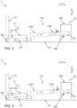
- Figure 3 shows the representation of the Figure 2 in a first assembly step of the connection kinematics 17.
- Figure 4 shows the representation of the Figure 2 in a second assembly step of the connection kinematics 17.
- Figure 5 shows the representation of the Figure 2 in a third assembly step of the connection kinematics 17.
- Figure 6 shows a Coupling element 17b of the connecting kinematics 17 of the cooking appliance 1 according to the invention directly from above.
- the coupling element 17 or the coupling rod 17 has an inner part 17ba and an outer part 17bb, which are connected to one another in a rotationally movable manner by means of corresponding internal and external threads, so that the coupling rod 17 can be rotated along its longitudinal direction of extension, see longitudinal axis X of the Figure 6 , is variable in length to a certain extent. If the two parts 17ba, 17bb of the coupling rod 17 are rotated relative to one another by means of the aforementioned rotational assembly movement E, this causes a change in length F along the elongated direction of extension.
- the coupling rod 17 is first connected to the drive lever 17a by means of the inner part 17ba in an articulated and thus pivotable manner, see Figure 3 . Furthermore, the remaining connecting kinematics 17 with spring holder 17c and connecting element 17d are mounted on the hinge body 10b and on the flap 14.
- the outer part 17bb is turned out of the inner part 17ba, cf.
- Figure 4 that the opposite end of the outer part 17bb can be connected to the corresponding end of the spring holder 17c in an articulated and thus pivotable manner, see Figure 5 .
- the inner part 17ba is fixed as the right-hand component during the pre-assembly of the connecting kinematics assembly 17.
- the outer part 17bb is rotated around itself as the left-hand component. This involves at least one rotation of the assembly movement E by 180° in order to fix the outer part 17bb (two-cut, see left in the Figure 6 ) with the adjacent component of the spring holder 17c.
- the outer part 17bb is thus rotated around its own axis until the holes (not marked) in the outer part 17bb and in the spring holder 17c are aligned.
- a stop for the outer part 17bb can be realized above the spring holder 17c, which determines the exact position of the hole in the spring holder 17c.
- a thread lock such as a self-locking nut, can be added to compensate for thread play.
Landscapes
- Engineering & Computer Science (AREA)
- Chemical & Material Sciences (AREA)
- Combustion & Propulsion (AREA)
- Mechanical Engineering (AREA)
- General Engineering & Computer Science (AREA)
- Cookers (AREA)
Applications Claiming Priority (2)
| Application Number | Priority Date | Filing Date | Title |
|---|---|---|---|
| DE102023132673 | 2023-11-23 | ||
| DE102023134410.2A DE102023134410B4 (de) | 2023-11-23 | 2023-12-08 | Haushaltsgerät mit beweglichem Verschlusselement |
Publications (1)
| Publication Number | Publication Date |
|---|---|
| EP4560201A1 true EP4560201A1 (fr) | 2025-05-28 |
Family
ID=93333539
Family Applications (1)
| Application Number | Title | Priority Date | Filing Date |
|---|---|---|---|
| EP24209402.7A Pending EP4560201A1 (fr) | 2023-11-23 | 2024-10-29 | Appareil ménager avec élément de fermeture mobile |
Country Status (1)
| Country | Link |
|---|---|
| EP (1) | EP4560201A1 (fr) |
Citations (9)
| Publication number | Priority date | Publication date | Assignee | Title |
|---|---|---|---|---|
| EP0702122A1 (fr) * | 1994-09-13 | 1996-03-20 | Merloni Elettrodomestici S.p.A. | Charnière avec point d'appui mobile pour appareils ménagers, en particulier pour fours de cuisson |
| DE19532568C1 (de) * | 1995-09-04 | 1996-11-07 | Porsche Ag | Antriebseinrichtung für ein Verdeck und/oder einen Verdeckkastendeckel eines Kraftfahrzeuges |
| US8292376B1 (en) * | 2010-01-27 | 2012-10-23 | Stelmasik Gregory A | Adjustable pivot assist mechanism for an enclosure door of a display case |
| EP2784257A1 (fr) | 2013-03-29 | 2014-10-01 | Nuova Star S.p.A. | Système de mise en mouvement d'une porte d'appareil électroménager et appareil électroménager avec le système |
| EP3438391A2 (fr) | 2017-08-04 | 2019-02-06 | Faringosi-Hinges S.r.l. | Charnière motorisée |
| KR102009500B1 (ko) * | 2018-03-22 | 2019-08-09 | 주식회사 에스앤에스정밀 | 도어 클로저 포암대 제조방법 및 이를 통해 제조된 도어 클로저 포암대 |
| DE102021100600A1 (de) | 2020-01-31 | 2021-08-05 | Miele & Cie. Kg | Haushaltsgerät, insbesondere wasserführendes Haushaltsgerät |
| DE202020005561U1 (de) | 2019-08-21 | 2021-08-30 | Miele & Cie. Kg | Gargerät mit einem mittels einer Tür verschließbaren Garraum |
| DE102020103291B4 (de) * | 2020-02-10 | 2021-12-30 | Miele & Cie. Kg | Haushaltgerät |
-
2024
- 2024-10-29 EP EP24209402.7A patent/EP4560201A1/fr active Pending
Patent Citations (9)
| Publication number | Priority date | Publication date | Assignee | Title |
|---|---|---|---|---|
| EP0702122A1 (fr) * | 1994-09-13 | 1996-03-20 | Merloni Elettrodomestici S.p.A. | Charnière avec point d'appui mobile pour appareils ménagers, en particulier pour fours de cuisson |
| DE19532568C1 (de) * | 1995-09-04 | 1996-11-07 | Porsche Ag | Antriebseinrichtung für ein Verdeck und/oder einen Verdeckkastendeckel eines Kraftfahrzeuges |
| US8292376B1 (en) * | 2010-01-27 | 2012-10-23 | Stelmasik Gregory A | Adjustable pivot assist mechanism for an enclosure door of a display case |
| EP2784257A1 (fr) | 2013-03-29 | 2014-10-01 | Nuova Star S.p.A. | Système de mise en mouvement d'une porte d'appareil électroménager et appareil électroménager avec le système |
| EP3438391A2 (fr) | 2017-08-04 | 2019-02-06 | Faringosi-Hinges S.r.l. | Charnière motorisée |
| KR102009500B1 (ko) * | 2018-03-22 | 2019-08-09 | 주식회사 에스앤에스정밀 | 도어 클로저 포암대 제조방법 및 이를 통해 제조된 도어 클로저 포암대 |
| DE202020005561U1 (de) | 2019-08-21 | 2021-08-30 | Miele & Cie. Kg | Gargerät mit einem mittels einer Tür verschließbaren Garraum |
| DE102021100600A1 (de) | 2020-01-31 | 2021-08-05 | Miele & Cie. Kg | Haushaltsgerät, insbesondere wasserführendes Haushaltsgerät |
| DE102020103291B4 (de) * | 2020-02-10 | 2021-12-30 | Miele & Cie. Kg | Haushaltgerät |
Similar Documents
| Publication | Publication Date | Title |
|---|---|---|
| EP3045639B1 (fr) | Charnière d'appareil ménager et procédö de fonctionnement d'une telle charnière | |
| EP2096360B1 (fr) | Porte d'appareil ménager | |
| DE102021111434B4 (de) | System, umfassend ein Möbel mit einer Einbaunische und ein Einbaugerät, und Verfahren zum Betrieb des Systems | |
| EP3572606B1 (fr) | Dispositif pour la préparation d'aliments et / ou de boissons ou pour le nettoyage d'un article à nettoyer | |
| EP2527749B1 (fr) | Appareil ménager avec porte et poignée | |
| EP3324124B1 (fr) | Appareil de cuisson avec dispositif de verrouillage | |
| EP4462029B1 (fr) | Appareil ménager doté d'une ouverture d'accès refermable | |
| EP3033968B1 (fr) | Four | |
| DE102023134410B4 (de) | Haushaltsgerät mit beweglichem Verschlusselement | |
| DE102017211203B4 (de) | Hebesystem für eine Haushaltsgeschirrspülmaschine oder ein Möbel | |
| DE102023118984B4 (de) | Haushaltsgerät mit einem kombinierten Sicherungselement zur Verwendung mit einem feststehenden Bauteil und einem beweglichen Bauteil | |
| EP2581666A1 (fr) | Porte pour un appareil ménager, appareil ménager équipé d'une porte et procédé de déplacement de la poignée de porte d'un appareil ménager | |
| EP4560201A1 (fr) | Appareil ménager avec élément de fermeture mobile | |
| DE102024113208B3 (de) | Haushaltsgerät mit beweglichem Verschlusselement | |
| EP4375466B1 (fr) | Charnière pour un dispositif, en particulier pour un appareil ménager ou un meuble, ainsi que dispositif, en particulier appareil ménager ou meuble | |
| EP2397770A1 (fr) | Appareil de cuisson et procédé | |
| DE102024112751B3 (de) | Haushaltsgerät mit motorisch beweglichem Verschlusselement | |
| DE102011085447A1 (de) | Haushaltsmaschine | |
| DE202013010945U1 (de) | Möbel und Vorrichtung zum Öffnen eines Möbelteils | |
| DE102012208435A1 (de) | Haushaltsgerät mit einer Tür und einer Verriegelungseinrichtung | |
| DE102023132657A1 (de) | Haushaltsgerät mit beweglichem Verschlusselement | |
| DE202017102929U1 (de) | Oberhitzegrill mit höhenverstellbarem Grillrost | |
| DE102024104817B4 (de) | Gargerät, vorzugsweise Dampfgargerät | |
| BE1029036B1 (de) | Gargerät mit einer höhenverstellbaren Gargutträgeraufnahme | |
| EP2740871B1 (fr) | Dispositif destiné à un appareil ménager comprenant une charnière et un dispositif de couplage et appareil ménager doté d'un tel dispositif |
Legal Events
| Date | Code | Title | Description |
|---|---|---|---|
| PUAI | Public reference made under article 153(3) epc to a published international application that has entered the european phase |
Free format text: ORIGINAL CODE: 0009012 |
|
| STAA | Information on the status of an ep patent application or granted ep patent |
Free format text: STATUS: THE APPLICATION HAS BEEN PUBLISHED |
|
| AK | Designated contracting states |
Kind code of ref document: A1 Designated state(s): AL AT BE BG CH CY CZ DE DK EE ES FI FR GB GR HR HU IE IS IT LI LT LU LV MC ME MK MT NL NO PL PT RO RS SE SI SK SM TR |
|
| STAA | Information on the status of an ep patent application or granted ep patent |
Free format text: STATUS: THE APPLICATION IS DEEMED TO BE WITHDRAWN |