EP4560203A1 - Système de pompe à chaleur - Google Patents
Système de pompe à chaleur Download PDFInfo
- Publication number
- EP4560203A1 EP4560203A1 EP23212010.5A EP23212010A EP4560203A1 EP 4560203 A1 EP4560203 A1 EP 4560203A1 EP 23212010 A EP23212010 A EP 23212010A EP 4560203 A1 EP4560203 A1 EP 4560203A1
- Authority
- EP
- European Patent Office
- Prior art keywords
- heat pump
- unit
- control unit
- units
- pump unit
- Prior art date
- Legal status (The legal status is an assumption and is not a legal conclusion. Google has not performed a legal analysis and makes no representation as to the accuracy of the status listed.)
- Withdrawn
Links
Images
Classifications
-
- F—MECHANICAL ENGINEERING; LIGHTING; HEATING; WEAPONS; BLASTING
- F24—HEATING; RANGES; VENTILATING
- F24D—DOMESTIC- OR SPACE-HEATING SYSTEMS, e.g. CENTRAL HEATING SYSTEMS; DOMESTIC HOT-WATER SUPPLY SYSTEMS; ELEMENTS OR COMPONENTS THEREFOR
- F24D3/00—Hot-water central heating systems
- F24D3/18—Hot-water central heating systems using heat pumps
-
- F—MECHANICAL ENGINEERING; LIGHTING; HEATING; WEAPONS; BLASTING
- F24—HEATING; RANGES; VENTILATING
- F24D—DOMESTIC- OR SPACE-HEATING SYSTEMS, e.g. CENTRAL HEATING SYSTEMS; DOMESTIC HOT-WATER SUPPLY SYSTEMS; ELEMENTS OR COMPONENTS THEREFOR
- F24D11/00—Central heating systems using heat accumulated in storage masses
- F24D11/02—Central heating systems using heat accumulated in storage masses using heat pumps
-
- F—MECHANICAL ENGINEERING; LIGHTING; HEATING; WEAPONS; BLASTING
- F24—HEATING; RANGES; VENTILATING
- F24D—DOMESTIC- OR SPACE-HEATING SYSTEMS, e.g. CENTRAL HEATING SYSTEMS; DOMESTIC HOT-WATER SUPPLY SYSTEMS; ELEMENTS OR COMPONENTS THEREFOR
- F24D12/00—Other central heating systems
- F24D12/02—Other central heating systems having more than one heat source
-
- F—MECHANICAL ENGINEERING; LIGHTING; HEATING; WEAPONS; BLASTING
- F24—HEATING; RANGES; VENTILATING
- F24D—DOMESTIC- OR SPACE-HEATING SYSTEMS, e.g. CENTRAL HEATING SYSTEMS; DOMESTIC HOT-WATER SUPPLY SYSTEMS; ELEMENTS OR COMPONENTS THEREFOR
- F24D17/00—Domestic hot-water supply systems
- F24D17/02—Domestic hot-water supply systems using heat pumps
-
- F—MECHANICAL ENGINEERING; LIGHTING; HEATING; WEAPONS; BLASTING
- F24—HEATING; RANGES; VENTILATING
- F24D—DOMESTIC- OR SPACE-HEATING SYSTEMS, e.g. CENTRAL HEATING SYSTEMS; DOMESTIC HOT-WATER SUPPLY SYSTEMS; ELEMENTS OR COMPONENTS THEREFOR
- F24D19/00—Details
- F24D19/10—Arrangement or mounting of control or safety devices
- F24D19/1006—Arrangement or mounting of control or safety devices for water heating systems
- F24D19/1009—Arrangement or mounting of control or safety devices for water heating systems for central heating
- F24D19/1039—Arrangement or mounting of control or safety devices for water heating systems for central heating the system uses a heat pump
-
- F—MECHANICAL ENGINEERING; LIGHTING; HEATING; WEAPONS; BLASTING
- F24—HEATING; RANGES; VENTILATING
- F24D—DOMESTIC- OR SPACE-HEATING SYSTEMS, e.g. CENTRAL HEATING SYSTEMS; DOMESTIC HOT-WATER SUPPLY SYSTEMS; ELEMENTS OR COMPONENTS THEREFOR
- F24D19/00—Details
- F24D19/10—Arrangement or mounting of control or safety devices
- F24D19/1006—Arrangement or mounting of control or safety devices for water heating systems
- F24D19/1051—Arrangement or mounting of control or safety devices for water heating systems for domestic hot water
- F24D19/1054—Arrangement or mounting of control or safety devices for water heating systems for domestic hot water the system uses a heat pump
Definitions
- the present invention relates to a heat pump system and a method for operating a heat pump system.
- Heat pump systems may comprise a plurality of heat pump units, which are fluidly connected and may operate in cascade.
- an external temperature sensor may be installed in the fluid circuit to determine the temperature of the fluid, e.g. in a manifold or collector tank.
- known controls often turn out to be prone to failure and implementation thereof may have drawbacks.
- the invention relates to a heat pump system for heating and/or cooling fluid, wherein the system comprises at least first and second heat pump units each configured for heating and/or cooling fluid; at least one temperature sensor related to/ in connection with at least the first heat pump unit for determining the inlet temperature and/or outlet temperature of the fluid at the first heat pump unit, and a master control unit for (common or joint) control of the first and second heat pump units on the basis of the determined inlet and/or outlet temperature, a slave control unit in connection with/ related to the second heat pump unit for (individual) control of the second heat pump unit, wherein the master control unit and the slave control unit are configured such that the master control unit sends control signals on the basis of the determined inlet and/or outlet temperature to the slave control unit, and the slave control unit receives said control signals and controls the operation of the second heat pump unit according to the received control signals.
- the temperature is determined in connection with the first heat pump unit, whilst the temperature as determined is not only used for control of the first heat pump unit, but also for control of the second heat pump unit (and any further heat pump unit).
- the temperature in connection with/related to the first heat pump unit may refer to the temperature in (inside) the first heat pump and/or the temperature in a port of the first heat pump unit, e.g. its direct piping connection, which may be outside the housing of the first heat pump.
- the corresponding (common) control unit using the determined temperature is referred to as a master control unit, wherein the second heat pump unit (and any further heat pump unit) have a control unit acting as a (individual) slave control unit (for the individual heat pump unit).
- the individual (slave) control unit may handle the internal control of the respective second heat pump unit(s).
- the plurality of heat pump units of the heat pump system shares a common control unit, namely the master control unit.
- the common control unit of the invention may control switching on/off of the first and second heat pump units and the associated speed management/request of the respective compressor.
- the slave control unit in connection with the second heat pump unit may be a control unit e.g. in a control box, inside the housing of the second heat pump unit or a control unit outside the housing of the second heat pump unit, for control of the second heat pump unit.
- the inlet or outlet temperature of the fluid (to be) heated/cooled in the first heat pump unit is determined, in particular at the inlet pipe or at the outlet pipe of the first heat pump unit.
- a temperature sensor for determining the inlet temperature and a temperature sensor for determining the outlet temperature is provided in the first heat pump unit.
- the at least one temperature sensor is located close to/at/in the first heat pump unit and may, additionally, be used for further purposes, such as for other control aspects. No extra temperature sensor for the common control in terms of the present invention may need to be installed (somewhere else) in the system, as no extra temperature sensor may be necessary for the common control.
- the control it is preferred to base the control on the input temperature at the first heat pump unit.
- the control may be based on the output temperature of the first heat pump unit.
- one of the temperature sensors of the first heat pump unit is optional for the present invention, but is understood that often both temperature sensor may be provided in the first heat pump unit.
- a specific advantage may be that no communication, let alone connection from a temperature sensor in the collector tank (which is typically installed in a building) to the heat pump units (which are often installed outside the building) is needed. It is evident that such connection, e.g. by way of a wire or wireless, is intricate in view of the building wall to be crossed and a relatively large distance. As such potential drawbacks may be avoided by the present invention, the present invention may be more reliable and less prone to failure. This increases the reliability and accuracy to achieve the heating and/or cooling target.
- all heat pump units may have their own control unit so each heat pump unit may run on its own if installed alone. And, when several units are connected, e.g. to the same HMI, the control of one heat pump unit may become the master and the other ones may become the slaves.
- a heat pump system of the invention is seen as versatile in that further heat pump units (with further control units) may be added even after installation of the initial heat pump system, in particular after installation of the master control unit.
- the control units of further heat pump units may serve as further slave control units.
- the present invention allows for parallel installation of a plurality of heat pump units (i.e. of at least two heat pump units), i.e. in cascade, and a common master control. More specifically, the master control unit may adjust operation of the plurality of heat pump units based on various parameters, e.g. aiming at optimizing the coefficient of performance of the plurality of heat pump units as a whole and/or ensuring that the power and temperature requirement is fulfilled. Additionally, an attempt may be to prolong the overall lifetime of the heat pump system in its entirety by equalizing the running hours of the individual heat pump units amongst the plurality of heat pump units. This supports to extend the lifetime of the installation as a whole.
- the temperature as measured by the temperature sensor in the first heat pump unit may slightly differ from the actual temperature of the fluid at other location in the fluid circuit, e.g. such as in a tank, due to potential thermal loss with ambient air in the pipe (reduction of temperature in case of heating mode, because the fluid of the system is hotter than ambient air).
- a corrective may be used to compensate for this thermal loss, depending of the insulation performance, the external conditions and the length of the connection between the circuitry, tank etc. and the first heat pump unit.
- heat pump units of the present invention may be ground source or air source heat pump units. It is possible that different heat pumps are comprised in the plurality of heat pump units.
- the first heat pump unit may be an air source heat pump unit, while the second heat pump unit is a ground source heat pump unit.
- the same type of heat pumps is present in the system. More preferably, the heat pumps have the same nominal (heating/cooling) capacity.
- a heat pump unit of the invention may have its entire refrigerant circuit of the heat pump included in a single unit, representing a so-called monobloc unit.
- the heat pump unit may be divided into two separated sub-units, representing a so-called split system.
- the heat pump unit may comprise a sub-unit (to be) installed indoor, and a sub-unit (to be) installed outdoor.
- the single unit may be installed indoor or outdoor.
- the invention concerns both monobloc and split units.
- the invention may be of particular relevance when the heat pump unit is an outdoor monobloc unit, as the distance travelled by the heated fluid to the (indoor) tank is long, including passing through the wall(s) of the building in which the tank is installed.
- At least one of the heat pump units is for centralized heating/cooling, and at least another one of plurality of heat pump units is for decentralized heating/cooling.
- a central heat pump unit may cover the base load and one or more decentralized heat pump units may cover peak loads.
- the fluid heated/cooled by the heat pump system may be a liquid.
- the fluid heated/cooled by the heat pump system may be used for central heating, e.g. emitting heating/cold to a building and may be preferably primary water in a closed loop circuit.
- the fluid may be the refrigerant of the frigorific circuit of the heat pump units.
- the present invention relates to a plurality of heat pump units i.e. to at least two heat pump units. If more than two heat pump units are provided, these further heat pump units (such as a third, fourth, fifth... heat pump unit) may correspond to the second heat pump unit as disclosed herein. In other words, the disclosure provided herein with respect to the second heat pump unit may extend to any third, fourth, fifth ... heat pump units, i.e. the remaining heat pump units of the plurality of heat pump units. In particular, each of these further heat pump units comprises a slave control unit as disclosed.
- the master control unit and the slave control unit are configured to communicate with each other. This may mean that the master control unit and the slave control unit are configured to exchange signals. Hence, the reliability as to the control may be improved.
- the master control unit is, at the same time, configured for individual control of the first heat pump unit, and is optionally located in the first heat pump unit.
- the master control unit is not only responsible for the joint control of the first and second heat pump units, but also for control of the first heat pump unit with respect to individual control aspects.
- no separate control unit for individual control of the first heat pump unit needs to be provided. From a different perspective, this means that no additional control unit may need to be provided for the master control unit, but a control unit for the first heat pump unit may specifically be configured as (master) control unit also for control pertaining to the second heat pump unit.
- the master control unit is also used to (individually) control the first heat pump unit, this may mean that the first heat pump unit also controls the second heat pump unit (and any further heat pump unit).
- the (master) first heat pump unit may be seen as imposing control on the remaining (slave) heat pump units.
- transmission of control signals from the first heat pump unit comprising the master control unit to the second heat pump unit(s) can often be implemented with lower efforts.
- the present invention is not limited to a master control unit located in the same heat pump unit in which the temperature of the fluid is measured. It is conceivable that a master control unit is located outside any heat pump unit.
- the system comprises a tank for circulation of (primary) fluid, the fluid preferably being water-based (e.g. containing glycol), preferably water, wherein the tank has a tank supply pipe for supply with fluid from the first and/or second heat pump units, and a tank return pipe for return of fluid to the first and/or second heat pump units.
- the tank may be configured to heat and/or cool liquid (e.g. water) for a circuit in a building by way of the fluid heated and/or cooled by the first and/or second heat pump units, based on heat exchange between the fluid and the liquid in the tank.
- the circuit may be an open loop domestic circuit (e.g. sanitary water for tap water) or a closed loop circuit (e.g. for radiators).
- the tank may be free of a temperature sensor. In particular, the temperature of the fluid in the tank does not need to be measured for the control of the plurality of heat pump units.
- the at least first and second heat pump units are configured to operate in parallel.
- the heat pump units are in cascade.
- there may be a fluid connection providing fluid communication between the first and second heat pump units for joint heating and/or cooling of fluid and allowing for heating and/or cooling in parallel.
- a liquid circuit connects the heat pump units in parallel.
- the connection may be realized by at least two common pipes each going from the heat pump units to the liquid tank.
- each heat pump may be connected directly to the same liquid tank without common pipes.
- the first and second heat pump units each have a heat pump capacity
- the master control unit is configured to (jointly) control the heat pump capacity of each of the first and second heat pump units based on the determined input and/or output temperature. If the control of the first and second heat pump units relates to the capacity of the heat pump units, operation of the heat pump system may effectively be improved and optimized.
- At least one of the first and second heat pump units comprises a compressor for compressing refrigerant and an inverter for modifying the capacity, in particular the speed of the compressor, and is configured such that the speed of the compressor is adjustable. More specifically, the inverter adapts the frequency of the alternating current so as to increase or decrease the frequency of the rotation.
- the first and second heat pump units (and any further heat pump units of the plurality of heat pump units) comprises an inverter in addition to the compressor, so that the speed of the compressor of each of the heat pump units can be adjusted, i.e. is variable. Specifically, the speed of the compressor can be reduced, so that the compressor does not have to run at full speed when in operation.
- the heat pump units may be modulated heat pump units, allowing for modulated operation.
- This is in contrast to a heat pump unit which merely allows for on/off-operation, wherein operation is only possible at full speed.
- Adjusting the speed of the compressor so that the compressor runs at a reduced speed is preferable compared to repeatedly or intermittently stopping the compressor, as this may help to increase the lifetime of the compressor and, hence, of the heat pump unit.
- the workload of the heat pump unit to achieve the heating and/or according target may more accurately be met. This may help to save energy and, thus, costs.
- the master control unit is configured to control the compressor speed of each of the first and second heat pump units based on the determined input and/or output temperature, optionally such that the speed of at least one compressor does not exceed 90%, preferably not exceed 85% of the maximum speed of said compressor, and is more preferably between 40 and 85% of the maximum speed of said compressor.
- the contribution of the plurality of heat pump units to achieve the target may be chosen accordingly.
- operation of the compressors at full speed may want to be avoided, which means that the speed of the compressor is preferably less than 100%.
- the heating and/or cooling target can be met by operation of one of the heat pump units, wherein the compressor runs at less than 80% of the maximum speed of said compressor, the other heat pump unit(s) may be stopped, meaning that the speed of the other heat pump unit(s) is zero.
- one compressor may run at 60% of its maximum speed and the other compressor may run at 40% of its maximum speed rather than one compressor running at its maximum speed.
- Various controls which may aim at an optimized coefficient of performance are conceivable. It is noted that the heat pump units amongst the plurality of heat pump units may differ from each other as to their maximum speed of the compressor.
- all the heat pump units of the system have the same maximum capacity.
- the master control unit is configured to base the control on at least one of: the total running time, the remaining lifetime, the heat pump capacity, the noise level, status as to error or warning, and the icing and de-icing requirements of the first and/or second heat pump units. Determination of an appropriate control may relate to considerations pertaining to the entirety of the heat pump units or may relate to individual heat pump units. This may improve the lifetime of the individual heat pump units and/or of the entirety of the heat pump system.
- the master control unit is configured to control the at least first and second heat pump units such that, if the at least first and second heat pump units are each available to produce the heating requirement, in particular at 40 to 85% of its maximum speed, the heat pump unit with the lower/lowest total running time amongst the first and second heat pump units is chosen as only heat pump unit producing the heating requirement.
- the control may choose the unit with the lowest total running time.
- the control may aim at balancing the operating times of the heat pumps as much as possible.
- the master control unit is configured to control the heat pump units such that, if one or more heat pump units are available to produce the heating requirement, in particular at 40 to 85% of its maximum speed, the heat pump unit(s) with the lowest total running time amongst the heat pump units is/are chosen as heat pump unit(s) producing the heating or cooling requirement.
- the master control unit may control the heat pump units such that, if the second and third heat pump units are available to produce the heating requirement, in particular at 40 to 85% of its respective maximum speed, the heat pump unit(s) with the lowest total running time amongst the second and third heat pump units is/are chosen as (sole) heat pump unit(s) producing the heating or cooling requirement.
- the heat pump which is/are used will be the one(s) with the lowest total running time and being able to produce the heating requirement by being between 40 and 85% of the maximum speed.
- the temperature sensor is located on an (outer) surface of a heat pump unit inlet pipe for determination of the inlet temperature of the first heat pump unit and/or on an (outer) surface of a heat pump unit outlet pipe for determination of the outlet temperature of the first heat pump unit.
- This may be seen as an indirect temperature measurement, as the sensor is not in direct contact with the fluid, but in contact with a pipe, in particular an outer surface of the pipe, in which the fluid flows.
- An advantage is that potential leakage through a pipe is avoided if the sensor crosses the pipe wall. Also maintenance may be simplified.
- a copper pipe may support the accuracy of the measurement of the temperature of the fluid, as copper has a high thermal conductivity.
- a correction of the temperature as measured indirectly, which corrective is reflective of implications of indirect measurement, may optionally be applied.
- An alternative to the indirect measurement of the temperature of the fluid is a direct measurement of the temperature of the fluid, in particular inside the pipe.
- a supplementary temperature sensor is provided in the second heat pump unit for determining an inlet and/or outlet temperature of the fluid in at least one of a heat pump unit inlet pipe and a heat pump unit outlet pipe of the second heat pump unit, respectively, wherein optionally the master control unit is configured to control the first and second heat pump units based on the input and/or output temperature of the second heat pump unit. If a temperature sensor is not only provided in the first heat pump unit, but also in the second heat pump unit, this may be preferable in terms of safety and reliability. If the temperature sensor in the first heat pump unit were broken, determination of the temperature may, for the control of the master control unit, be provided based on the determination of the temperature in the second heat pump unit.
- the first and second heat pump units, and/or optionally the master control unit and the slave control unit are physically connected to each other for communication of the control signals, preferably by way of a signal wire, for instance via a modbus cable between the heat pump units.
- the communication between the master control unit and the slave control unit may be wireless or by way of a wire.
- a wire allows for direct and reliable connection. As heat pump units are often located (relatively) close to one another, a transmission via a wire may often be realized without undue efforts. In particular, the wire may not need to pass through building walls, which may otherwise be the case if the heat pump unit is installed outdoor and the temperature sensor for the common control is in the tank (which is inside the building).
- the invention also relates to a method of operating a heat pump system, wherein fluid is heated and/or cooled by at least one of first and second heat pump units, wherein at least first and second heat pump units are provided, at least in connection with/at the first heat pump unit, the temperature of the fluid is determined before and/or after the fluid is heated/cooled by the first heat pump unit, and operation of the first and second heat pumps units is controlled by way of a master control unit based on the determined temperature, wherein the master control unit sends control signals based on the determined temperature to a slave control unit in connection with/related to/in the second heat pump unit, and the slave control unit receives said control signals and controls the operation of the second heat pump unit accordingly.
- the master control unit individually controls the first heat pump unit, and is optionally located in the first heat pump unit.
- the master control unit may not only be responsible for the common control of the plurality of heat pump units, but also for the individual control of the first heat pump unit.
- the method of the invention may relate to the system of the invention.
- the method of the invention may be based on the control units of the system of the invention.
- the control unit(s) of the system of the invention may realize the method of the invention.
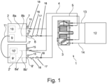
- FIG. 1 shows a heat pump system 1 for heating and/or cooling fluid in a common fluid circuit.
- the heat pump system 1 comprises a first heat pump unit 2 and a second heat pump unit 2'.
- Each of the heat pump units 2, 2' has a heat pump unit inlet pipe 6, 6' and a heat pump unit outlet pipe 7, 7'.
- fluid flows in a tank 3 for heat exchange with a liquid not in fluid communication with the fluid, for example water of a domestic water tank. Fluid enters the tank 3 via the tank supply pipe 4 and exits the tank via the tank return pipe 5.
- the pump inlet pipe 6, 6' supplies fluid to the respective heat pump unit 2, 2' and is connected to the tank return pipe 5.
- the pump outlet pipe 7, 7' returns fluid from the respective heat pump unit 2, 2' to the tank 3 via the tank supply pipe 4.
- no tank 3 may be present.
- further devices may be present, such as a hydraulic separator (not shown).
- the heat pump units 2, 2' and the tank 3 are part of a fluid circuit, in which the heat pump units 2, 2' represent parallel fluid flows. As such, the heat pump units 2, 2' are operational in parallel in that they share a fluid circuit. In other words, the heat pump units 2, 2' are in cascade. However, it is not necessary that all heat pump units 2, 2' are indeed operating. How operation is actually controlled is explained below.
- the fluid circuit in figure 1 shows further details: Pressure gauges 15, (water) filters 16, check valve /one-way valves 17 and manual valves 18 may be provided.
- the master control unit 9 is located in the first heat pump unit 2 and serves for joint control of both the first and second heat pump units 2, 2' and also for individual control of the first heat pump unit 2.
- Fluid in the tank 3 is in heat-exchange with consumption liquid (separately from the fluid) accommodated in the tank 3.
- the liquid is used in a circuit 12 which is connected to the tank 3 via a consumption circuit supply pipe 13 and a consumption circuit return pipe 14.
- Consumption may relate to consumption of the energy delivered by the consumption liquid (heat or cold) e.g. by emitters, and/or to the consumption of the domestic liquid.
- a temperature sensor 8a, 8b is provided in the first heat pump unit 2. This temperature sensor 8a, 8b determines the inlet temperature or outlet temperature of the fluid.
- a temperature sensor 8a for detecting the outlet temperature of the fluid is located at the heat pump outlet pipe 7 inside the heat pump unit 2 and a temperature sensor 8b for detecting an inlet temperature of the fluid is located at the heat pump inlet pipe 6 inside the heat pump unit 2.
- corresponding temperature sensors 8a', 8b' are provided in the second heat pump unit 2'. These sensors 8a', 8b' are supplementary for the invention and may be provided for safety purposes, just in case the temperature sensors 8a, 8b are out of function.
- a master control unit 9 is comprised in the first heat pump unit 2, and controls not only the first heat pump unit 2, but also the second heat pump unit 2', based on the determination of the temperature by the temperature sensor(s) 8a, 8b in the first heat pump unit 2.
- the master control unit 9 communicates with the second heat pump unit 2' in that it sends control signals/commands to the slave control unit 9' of the second heat pump unit 2'. Such commands relate to the operation of the second heat pump unit 2'.
- the slave control unit 9' receives the signals from the master control unit 9 and controls the operation of the second heat pump unit 2' accordingly.
- the master control unit 9 and the slave control unit 9' are in communication with each other and exchange signals.
- a wire 11 physically connects the master control unit 9 and the slave control unit 9'.
- the first heat pump unit 2 and the second heat pump unit 2' may be located relatively close to each other and e.g. on the same side of a building, a relatively short wire 11 may be sufficient.
- the temperature sensors 8a, 8b, 8a', 8b' are located on the respective heat pump inlet pipe or heat pump outlet pipe for indirect measurement of the temperature of the fluid.
- the first and second heat pump units 2, 2' each have a heat pump capacity, wherein the master control unit 9 controls the heat pump capacity of each of the first and second heat pump units 2, 2'.
- the control is based on the determined input and/or output temperature and considers various factors such as the total running time, the remaining lifetime, the heat pump capacity, the noise level, icing and de-icing requirements. On this basis, the capacity at which the plurality of pump units runs is chosen. This is possible if the plurality of heat pump units comprises inverters for modifying the capacity of the compressor. More specifically, the speed of the compressor can be adjusted for each heat pump unit 2, 2'.
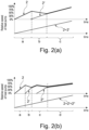
- first and second heat pump units operate in cascade.
- the total request increases with time, wherein initially, during interval a, only the first heat pump unit 2 operates.
- the second heat pump unit 2' supports the first heat pump unit 2 to meet the heating and/or cooling target. More specifically, in interval b, the capacity of the first heat pump unit 2 is continuously reduced while the capacity of the second heat pump unit 2' is continuously increased.
- the first and second heat pump units 2, 2' run with continuously increasing capacities in order to meet the increasing total request.
- the capacity of the first heat pump unit 2 reaches 50% of the maximum capacity at the end of interval a
- the second heat pump unit 2' starts operating so as to reduce the workload of the first heat pump unit 2.
- both first and second heat pump units 2, 2' are working in a preferred and more efficient frequency rate range.
- three heat pump units 2, 2', 2" are part of the heat pump system and in cascade, wherein the third heat pump unit 2" is provided in addition to first 2 and second 2' heat pump units.
- the first heat pump unit 2 can meet the total request alone.
- the second heat pump unit 2' becomes active while the first heat pump 2 is also active.
- all three heat pump units are working, wherein the capacity of the third heat pump unit 2" continuously increases and the capacities of the first and second heat pump units 2, 2' decreases.
- all three heat pump units are in operation, with continuously and equally increasing capacities. Thanks to associated management of the heat pump units 2, 2', the more optimal frequency range of the compressor of each units may be preferred.
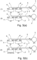
- Figure 3 is directed to various constellations with a master control unit 9 and a slave control unit 9' of the present invention.
- Figure 3(a) shows two different situations.
- the target temperature is 60°C.
- the temperature of the fluid in the tank 3 is 50°C, which is seen as corresponding to the pump inlet temperature at the first and second heat pump units 2, 2'.
- the second heat pump unit 2' is not working, as the request of power of 20 kW can be met by the first heat pump unit 2 alone, see the outlet temperature of the first heat pump unit 2 of 55°C.
- the target temperature is also 60°C and the inlet temperature is 50°C.
- the first heat pump unit 2 is not operating, but the second heat pump unit 2' is operating.
- the master control unit 9 may decide whether situation (1) or (2) is to be realized depending on the remaining lifetime of the first and second heat pump units, for example.
- Figure 3(b) shows two further constellations, which are close to those of figure 3(a) , but in which the power request is higher, namely 40 kW, for the same target temperature of 60°C.
- the master control unit 9 has decided to let both first and second heat pump units 2, 2' operate. It is indicated in figure 2(b) (1) that the outlet temperature of the first and second heat pump units is 55°C each.
- Situation (2) reflects that the first heat pump unit 2 is defrosting and is, therefore, not available for heating.
- the master control unit 9 is about to initiate operation of the second heat pump unit 2' so as to meet the heating request. As long as defrosting of the first heat pump unit 2 is ongoing, only the second heat pump unit 2' will be available for heating. By doing so, the second heat pump unit 2' is able to at least partially compensate for the temperature loss during defrosting of the first heat pump unit 2.
Landscapes
- Engineering & Computer Science (AREA)
- Physics & Mathematics (AREA)
- Thermal Sciences (AREA)
- Chemical & Material Sciences (AREA)
- Combustion & Propulsion (AREA)
- Mechanical Engineering (AREA)
- General Engineering & Computer Science (AREA)
- Heat-Pump Type And Storage Water Heaters (AREA)
- Air Conditioning Control Device (AREA)
Priority Applications (2)
| Application Number | Priority Date | Filing Date | Title |
|---|---|---|---|
| EP23212010.5A EP4560203A1 (fr) | 2023-11-24 | 2023-11-24 | Système de pompe à chaleur |
| PCT/EP2024/083219 WO2025109133A1 (fr) | 2023-11-24 | 2024-11-22 | Système de pompe à chaleur |
Applications Claiming Priority (1)
| Application Number | Priority Date | Filing Date | Title |
|---|---|---|---|
| EP23212010.5A EP4560203A1 (fr) | 2023-11-24 | 2023-11-24 | Système de pompe à chaleur |
Publications (1)
| Publication Number | Publication Date |
|---|---|
| EP4560203A1 true EP4560203A1 (fr) | 2025-05-28 |
Family
ID=88969809
Family Applications (1)
| Application Number | Title | Priority Date | Filing Date |
|---|---|---|---|
| EP23212010.5A Withdrawn EP4560203A1 (fr) | 2023-11-24 | 2023-11-24 | Système de pompe à chaleur |
Country Status (2)
| Country | Link |
|---|---|
| EP (1) | EP4560203A1 (fr) |
| WO (1) | WO2025109133A1 (fr) |
Citations (8)
| Publication number | Priority date | Publication date | Assignee | Title |
|---|---|---|---|---|
| EP0204521A2 (fr) * | 1985-05-29 | 1986-12-10 | York International Ltd | Système de chauffage et/ou de refroidissement |
| JP2004340533A (ja) * | 2003-05-19 | 2004-12-02 | Matsushita Electric Ind Co Ltd | ヒートポンプ給湯空調装置 |
| US20110315093A1 (en) * | 2009-03-30 | 2011-12-29 | Mitsubishi Electric Corporation | Fluid heating system, fluid heating method, fluid heating control system, control apparatus, and control method |
| JP2016223745A (ja) * | 2015-06-03 | 2016-12-28 | 三菱電機株式会社 | 貯湯式給湯機 |
| EP3136013A1 (fr) * | 2014-04-25 | 2017-03-01 | Mitsubishi Electric Corporation | Système de refroidissement de pompe à chaleur et procédé de commande associé |
| DE102020204276A1 (de) * | 2020-04-02 | 2021-10-07 | Robert Bosch Gesellschaft mit beschränkter Haftung | Heizungsvorrichtung und Verfahren zum Betrieb einer Heizungsvorrichtung |
| CN113883579A (zh) * | 2021-10-29 | 2022-01-04 | 青岛海信日立空调系统有限公司 | 一种水系统空调 |
| EP3995763A1 (fr) * | 2019-07-03 | 2022-05-11 | Mitsubishi Electric Corporation | Dispositif à cycle frigorifique |
Family Cites Families (4)
| Publication number | Priority date | Publication date | Assignee | Title |
|---|---|---|---|---|
| GB2514000B (en) | 2014-04-10 | 2015-03-25 | Esg Pool Ventilation Ltd | A fluid heating and/or cooling system and related methods |
| JP6592858B2 (ja) * | 2015-04-14 | 2019-10-23 | 三菱重工サーマルシステムズ株式会社 | 制御装置、制御方法及びプログラム |
| SE541234C2 (en) | 2015-11-20 | 2019-05-07 | Sens Geoenergy Storage Ab | Methods and systems for heat pumping |
| CZ2022492A3 (cs) | 2022-11-22 | 2023-11-15 | KovalĂk Electrotechnics s.r.o. | Zapojení tepelných čerpadel a způsob řízení tepelných čerpadel tohoto zapojení |
-
2023
- 2023-11-24 EP EP23212010.5A patent/EP4560203A1/fr not_active Withdrawn
-
2024
- 2024-11-22 WO PCT/EP2024/083219 patent/WO2025109133A1/fr active Pending
Patent Citations (8)
| Publication number | Priority date | Publication date | Assignee | Title |
|---|---|---|---|---|
| EP0204521A2 (fr) * | 1985-05-29 | 1986-12-10 | York International Ltd | Système de chauffage et/ou de refroidissement |
| JP2004340533A (ja) * | 2003-05-19 | 2004-12-02 | Matsushita Electric Ind Co Ltd | ヒートポンプ給湯空調装置 |
| US20110315093A1 (en) * | 2009-03-30 | 2011-12-29 | Mitsubishi Electric Corporation | Fluid heating system, fluid heating method, fluid heating control system, control apparatus, and control method |
| EP3136013A1 (fr) * | 2014-04-25 | 2017-03-01 | Mitsubishi Electric Corporation | Système de refroidissement de pompe à chaleur et procédé de commande associé |
| JP2016223745A (ja) * | 2015-06-03 | 2016-12-28 | 三菱電機株式会社 | 貯湯式給湯機 |
| EP3995763A1 (fr) * | 2019-07-03 | 2022-05-11 | Mitsubishi Electric Corporation | Dispositif à cycle frigorifique |
| DE102020204276A1 (de) * | 2020-04-02 | 2021-10-07 | Robert Bosch Gesellschaft mit beschränkter Haftung | Heizungsvorrichtung und Verfahren zum Betrieb einer Heizungsvorrichtung |
| CN113883579A (zh) * | 2021-10-29 | 2022-01-04 | 青岛海信日立空调系统有限公司 | 一种水系统空调 |
Also Published As
| Publication number | Publication date |
|---|---|
| WO2025109133A1 (fr) | 2025-05-30 |
Similar Documents
| Publication | Publication Date | Title |
|---|---|---|
| US5946926A (en) | Variable flow chilled fluid cooling system | |
| CN110274361B (zh) | 水多联空调系统及其变频水泵的控制方法 | |
| US9488400B2 (en) | System for managing lubricant levels in tandem compressor assemblies of an HVAC system | |
| KR20120039650A (ko) | 열원 시스템 | |
| KR20070004932A (ko) | 고정식 및 가변 압축기 시스템 용량 제어 | |
| CA2551824A1 (fr) | Commande de capacite adaptative integree pour une unite de refroidissement commandee par turbine a vapeur | |
| CN101865496A (zh) | 冷冻水直供系统及方法 | |
| JP4406778B2 (ja) | 冷水循環システム | |
| JP4333818B2 (ja) | 冷水循環システム | |
| CN112923508A (zh) | 空调冷却水系统的控制方法 | |
| US11143434B2 (en) | Refrigeration cycle apparatus | |
| CN111365931A (zh) | 一种工业冷却水平衡优化节能控制系统 | |
| JP4301238B2 (ja) | 冷水循環システム | |
| JP2009115452A5 (fr) | ||
| JP5816422B2 (ja) | 冷凍装置の排熱利用システム | |
| WO2017009955A1 (fr) | Système de réfrigération | |
| CN111089371A (zh) | 一种电子厂房冷源站控制系统及其控制方法 | |
| JPH04151466A (ja) | 空気調和機 | |
| EP4560203A1 (fr) | Système de pompe à chaleur | |
| JP4569661B2 (ja) | 冷水循環システム | |
| JP4748175B2 (ja) | 冷水循環システム | |
| WO2013175890A1 (fr) | Système de climatisation, système de climatisation intégré et dispositif de commande | |
| EP3859216B1 (fr) | Pompe à chaleur et procédé associé | |
| CN106546020B (zh) | 空调系统 | |
| CN218600030U (zh) | 多级制冷系统 |
Legal Events
| Date | Code | Title | Description |
|---|---|---|---|
| PUAI | Public reference made under article 153(3) epc to a published international application that has entered the european phase |
Free format text: ORIGINAL CODE: 0009012 |
|
| STAA | Information on the status of an ep patent application or granted ep patent |
Free format text: STATUS: THE APPLICATION HAS BEEN PUBLISHED |
|
| AK | Designated contracting states |
Kind code of ref document: A1 Designated state(s): AL AT BE BG CH CY CZ DE DK EE ES FI FR GB GR HR HU IE IS IT LI LT LU LV MC ME MK MT NL NO PL PT RO RS SE SI SK SM TR |
|
| STAA | Information on the status of an ep patent application or granted ep patent |
Free format text: STATUS: THE APPLICATION IS DEEMED TO BE WITHDRAWN |
|
| 18D | Application deemed to be withdrawn |
Effective date: 20251129 |