EP4560221A1 - Chauffe-eau à stratification améliorée - Google Patents
Chauffe-eau à stratification améliorée Download PDFInfo
- Publication number
- EP4560221A1 EP4560221A1 EP24215253.6A EP24215253A EP4560221A1 EP 4560221 A1 EP4560221 A1 EP 4560221A1 EP 24215253 A EP24215253 A EP 24215253A EP 4560221 A1 EP4560221 A1 EP 4560221A1
- Authority
- EP
- European Patent Office
- Prior art keywords
- temperature
- storage tank
- connection
- water
- outlet
- Prior art date
- Legal status (The legal status is an assumption and is not a legal conclusion. Google has not performed a legal analysis and makes no representation as to the accuracy of the status listed.)
- Pending
Links
Images



Classifications
-
- F—MECHANICAL ENGINEERING; LIGHTING; HEATING; WEAPONS; BLASTING
- F24—HEATING; RANGES; VENTILATING
- F24D—DOMESTIC- OR SPACE-HEATING SYSTEMS, e.g. CENTRAL HEATING SYSTEMS; DOMESTIC HOT-WATER SUPPLY SYSTEMS; ELEMENTS OR COMPONENTS THEREFOR
- F24D19/00—Details
- F24D19/10—Arrangement or mounting of control or safety devices
- F24D19/1006—Arrangement or mounting of control or safety devices for water heating systems
- F24D19/1066—Arrangement or mounting of control or safety devices for water heating systems for the combination of central heating and domestic hot water
- F24D19/1069—Arrangement or mounting of control or safety devices for water heating systems for the combination of central heating and domestic hot water regulation in function of the temperature of the domestic hot water
-
- F—MECHANICAL ENGINEERING; LIGHTING; HEATING; WEAPONS; BLASTING
- F24—HEATING; RANGES; VENTILATING
- F24D—DOMESTIC- OR SPACE-HEATING SYSTEMS, e.g. CENTRAL HEATING SYSTEMS; DOMESTIC HOT-WATER SUPPLY SYSTEMS; ELEMENTS OR COMPONENTS THEREFOR
- F24D19/00—Details
- F24D19/10—Arrangement or mounting of control or safety devices
- F24D19/1006—Arrangement or mounting of control or safety devices for water heating systems
- F24D19/1066—Arrangement or mounting of control or safety devices for water heating systems for the combination of central heating and domestic hot water
- F24D19/1075—Arrangement or mounting of control or safety devices for water heating systems for the combination of central heating and domestic hot water the system uses solar energy
-
- F—MECHANICAL ENGINEERING; LIGHTING; HEATING; WEAPONS; BLASTING
- F24—HEATING; RANGES; VENTILATING
- F24D—DOMESTIC- OR SPACE-HEATING SYSTEMS, e.g. CENTRAL HEATING SYSTEMS; DOMESTIC HOT-WATER SUPPLY SYSTEMS; ELEMENTS OR COMPONENTS THEREFOR
- F24D3/00—Hot-water central heating systems
- F24D3/08—Hot-water central heating systems in combination with systems for domestic hot-water supply
-
- F—MECHANICAL ENGINEERING; LIGHTING; HEATING; WEAPONS; BLASTING
- F24—HEATING; RANGES; VENTILATING
- F24H—FLUID HEATERS, e.g. WATER OR AIR HEATERS, HAVING HEAT-GENERATING MEANS, e.g. HEAT PUMPS, IN GENERAL
- F24H1/00—Water heaters, e.g. boilers, continuous-flow heaters or water-storage heaters
- F24H1/18—Water-storage heaters
- F24H1/185—Water-storage heaters using electric energy supply
-
- F—MECHANICAL ENGINEERING; LIGHTING; HEATING; WEAPONS; BLASTING
- F24—HEATING; RANGES; VENTILATING
- F24H—FLUID HEATERS, e.g. WATER OR AIR HEATERS, HAVING HEAT-GENERATING MEANS, e.g. HEAT PUMPS, IN GENERAL
- F24H1/00—Water heaters, e.g. boilers, continuous-flow heaters or water-storage heaters
- F24H1/18—Water-storage heaters
- F24H1/20—Water-storage heaters with immersed heating elements, e.g. electric elements or furnace tubes
- F24H1/201—Water-storage heaters with immersed heating elements, e.g. electric elements or furnace tubes using electric energy supply
- F24H1/202—Water-storage heaters with immersed heating elements, e.g. electric elements or furnace tubes using electric energy supply with resistances
-
- F—MECHANICAL ENGINEERING; LIGHTING; HEATING; WEAPONS; BLASTING
- F24—HEATING; RANGES; VENTILATING
- F24H—FLUID HEATERS, e.g. WATER OR AIR HEATERS, HAVING HEAT-GENERATING MEANS, e.g. HEAT PUMPS, IN GENERAL
- F24H15/00—Control of fluid heaters
- F24H15/10—Control of fluid heaters characterised by the purpose of the control
- F24H15/16—Reducing cost using the price of energy, e.g. choosing or switching between different energy sources
-
- F—MECHANICAL ENGINEERING; LIGHTING; HEATING; WEAPONS; BLASTING
- F24—HEATING; RANGES; VENTILATING
- F24H—FLUID HEATERS, e.g. WATER OR AIR HEATERS, HAVING HEAT-GENERATING MEANS, e.g. HEAT PUMPS, IN GENERAL
- F24H15/00—Control of fluid heaters
- F24H15/10—Control of fluid heaters characterised by the purpose of the control
- F24H15/174—Supplying heated water with desired temperature or desired range of temperature
-
- F—MECHANICAL ENGINEERING; LIGHTING; HEATING; WEAPONS; BLASTING
- F24—HEATING; RANGES; VENTILATING
- F24H—FLUID HEATERS, e.g. WATER OR AIR HEATERS, HAVING HEAT-GENERATING MEANS, e.g. HEAT PUMPS, IN GENERAL
- F24H15/00—Control of fluid heaters
- F24H15/10—Control of fluid heaters characterised by the purpose of the control
- F24H15/184—Preventing harm to users from exposure to heated water, e.g. scalding
-
- F—MECHANICAL ENGINEERING; LIGHTING; HEATING; WEAPONS; BLASTING
- F24—HEATING; RANGES; VENTILATING
- F24H—FLUID HEATERS, e.g. WATER OR AIR HEATERS, HAVING HEAT-GENERATING MEANS, e.g. HEAT PUMPS, IN GENERAL
- F24H15/00—Control of fluid heaters
- F24H15/20—Control of fluid heaters characterised by control inputs
- F24H15/212—Temperature of the water
- F24H15/215—Temperature of the water before heating
-
- F—MECHANICAL ENGINEERING; LIGHTING; HEATING; WEAPONS; BLASTING
- F24—HEATING; RANGES; VENTILATING
- F24H—FLUID HEATERS, e.g. WATER OR AIR HEATERS, HAVING HEAT-GENERATING MEANS, e.g. HEAT PUMPS, IN GENERAL
- F24H15/00—Control of fluid heaters
- F24H15/20—Control of fluid heaters characterised by control inputs
- F24H15/212—Temperature of the water
- F24H15/219—Temperature of the water after heating
-
- F—MECHANICAL ENGINEERING; LIGHTING; HEATING; WEAPONS; BLASTING
- F24—HEATING; RANGES; VENTILATING
- F24H—FLUID HEATERS, e.g. WATER OR AIR HEATERS, HAVING HEAT-GENERATING MEANS, e.g. HEAT PUMPS, IN GENERAL
- F24H15/00—Control of fluid heaters
- F24H15/20—Control of fluid heaters characterised by control inputs
- F24H15/212—Temperature of the water
- F24H15/223—Temperature of the water in the water storage tank
- F24H15/225—Temperature of the water in the water storage tank at different heights of the tank
-
- F—MECHANICAL ENGINEERING; LIGHTING; HEATING; WEAPONS; BLASTING
- F24—HEATING; RANGES; VENTILATING
- F24H—FLUID HEATERS, e.g. WATER OR AIR HEATERS, HAVING HEAT-GENERATING MEANS, e.g. HEAT PUMPS, IN GENERAL
- F24H15/00—Control of fluid heaters
- F24H15/20—Control of fluid heaters characterised by control inputs
- F24H15/296—Information from neighbouring devices
-
- F—MECHANICAL ENGINEERING; LIGHTING; HEATING; WEAPONS; BLASTING
- F24—HEATING; RANGES; VENTILATING
- F24H—FLUID HEATERS, e.g. WATER OR AIR HEATERS, HAVING HEAT-GENERATING MEANS, e.g. HEAT PUMPS, IN GENERAL
- F24H15/00—Control of fluid heaters
- F24H15/30—Control of fluid heaters characterised by control outputs; characterised by the components to be controlled
- F24H15/305—Control of valves
- F24H15/31—Control of valves of valves having only one inlet port and one outlet port, e.g. flow rate regulating valves
-
- F—MECHANICAL ENGINEERING; LIGHTING; HEATING; WEAPONS; BLASTING
- F24—HEATING; RANGES; VENTILATING
- F24H—FLUID HEATERS, e.g. WATER OR AIR HEATERS, HAVING HEAT-GENERATING MEANS, e.g. HEAT PUMPS, IN GENERAL
- F24H15/00—Control of fluid heaters
- F24H15/30—Control of fluid heaters characterised by control outputs; characterised by the components to be controlled
- F24H15/305—Control of valves
- F24H15/315—Control of valves of mixing valves
-
- F—MECHANICAL ENGINEERING; LIGHTING; HEATING; WEAPONS; BLASTING
- F24—HEATING; RANGES; VENTILATING
- F24H—FLUID HEATERS, e.g. WATER OR AIR HEATERS, HAVING HEAT-GENERATING MEANS, e.g. HEAT PUMPS, IN GENERAL
- F24H15/00—Control of fluid heaters
- F24H15/30—Control of fluid heaters characterised by control outputs; characterised by the components to be controlled
- F24H15/335—Control of pumps, e.g. on-off control
- F24H15/34—Control of the speed of pumps
-
- F—MECHANICAL ENGINEERING; LIGHTING; HEATING; WEAPONS; BLASTING
- F24—HEATING; RANGES; VENTILATING
- F24H—FLUID HEATERS, e.g. WATER OR AIR HEATERS, HAVING HEAT-GENERATING MEANS, e.g. HEAT PUMPS, IN GENERAL
- F24H15/00—Control of fluid heaters
- F24H15/30—Control of fluid heaters characterised by control outputs; characterised by the components to be controlled
- F24H15/355—Control of heat-generating means in heaters
- F24H15/37—Control of heat-generating means in heaters of electric heaters
-
- F—MECHANICAL ENGINEERING; LIGHTING; HEATING; WEAPONS; BLASTING
- F24—HEATING; RANGES; VENTILATING
- F24H—FLUID HEATERS, e.g. WATER OR AIR HEATERS, HAVING HEAT-GENERATING MEANS, e.g. HEAT PUMPS, IN GENERAL
- F24H15/00—Control of fluid heaters
- F24H15/40—Control of fluid heaters characterised by the type of controllers
- F24H15/493—Control of fluid heaters characterised by the type of controllers specially adapted for enabling recognition of parts newly installed in the fluid heating system, e.g. for retrofitting or for repairing by replacing parts
-
- F—MECHANICAL ENGINEERING; LIGHTING; HEATING; WEAPONS; BLASTING
- F24—HEATING; RANGES; VENTILATING
- F24H—FLUID HEATERS, e.g. WATER OR AIR HEATERS, HAVING HEAT-GENERATING MEANS, e.g. HEAT PUMPS, IN GENERAL
- F24H9/00—Details
- F24H9/0005—Details for water heaters
- F24H9/001—Guiding means
- F24H9/0015—Guiding means in water channels
-
- F—MECHANICAL ENGINEERING; LIGHTING; HEATING; WEAPONS; BLASTING
- F24—HEATING; RANGES; VENTILATING
- F24H—FLUID HEATERS, e.g. WATER OR AIR HEATERS, HAVING HEAT-GENERATING MEANS, e.g. HEAT PUMPS, IN GENERAL
- F24H9/00—Details
- F24H9/20—Arrangement or mounting of control or safety devices
- F24H9/2007—Arrangement or mounting of control or safety devices for water heaters
- F24H9/2014—Arrangement or mounting of control or safety devices for water heaters using electrical energy supply
- F24H9/2021—Storage heaters
-
- F—MECHANICAL ENGINEERING; LIGHTING; HEATING; WEAPONS; BLASTING
- F24—HEATING; RANGES; VENTILATING
- F24D—DOMESTIC- OR SPACE-HEATING SYSTEMS, e.g. CENTRAL HEATING SYSTEMS; DOMESTIC HOT-WATER SUPPLY SYSTEMS; ELEMENTS OR COMPONENTS THEREFOR
- F24D2200/00—Heat sources or energy sources
- F24D2200/02—Photovoltaic energy
-
- F—MECHANICAL ENGINEERING; LIGHTING; HEATING; WEAPONS; BLASTING
- F24—HEATING; RANGES; VENTILATING
- F24D—DOMESTIC- OR SPACE-HEATING SYSTEMS, e.g. CENTRAL HEATING SYSTEMS; DOMESTIC HOT-WATER SUPPLY SYSTEMS; ELEMENTS OR COMPONENTS THEREFOR
- F24D2200/00—Heat sources or energy sources
- F24D2200/08—Electric heater
-
- F—MECHANICAL ENGINEERING; LIGHTING; HEATING; WEAPONS; BLASTING
- F24—HEATING; RANGES; VENTILATING
- F24D—DOMESTIC- OR SPACE-HEATING SYSTEMS, e.g. CENTRAL HEATING SYSTEMS; DOMESTIC HOT-WATER SUPPLY SYSTEMS; ELEMENTS OR COMPONENTS THEREFOR
- F24D2220/00—Components of central heating installations excluding heat sources
- F24D2220/02—Fluid distribution means
- F24D2220/0207—Pumps
-
- F—MECHANICAL ENGINEERING; LIGHTING; HEATING; WEAPONS; BLASTING
- F24—HEATING; RANGES; VENTILATING
- F24D—DOMESTIC- OR SPACE-HEATING SYSTEMS, e.g. CENTRAL HEATING SYSTEMS; DOMESTIC HOT-WATER SUPPLY SYSTEMS; ELEMENTS OR COMPONENTS THEREFOR
- F24D2220/00—Components of central heating installations excluding heat sources
- F24D2220/04—Sensors
- F24D2220/042—Temperature sensors
-
- F—MECHANICAL ENGINEERING; LIGHTING; HEATING; WEAPONS; BLASTING
- F24—HEATING; RANGES; VENTILATING
- F24D—DOMESTIC- OR SPACE-HEATING SYSTEMS, e.g. CENTRAL HEATING SYSTEMS; DOMESTIC HOT-WATER SUPPLY SYSTEMS; ELEMENTS OR COMPONENTS THEREFOR
- F24D2220/00—Components of central heating installations excluding heat sources
- F24D2220/08—Storage tanks
-
- F—MECHANICAL ENGINEERING; LIGHTING; HEATING; WEAPONS; BLASTING
- F24—HEATING; RANGES; VENTILATING
- F24H—FLUID HEATERS, e.g. WATER OR AIR HEATERS, HAVING HEAT-GENERATING MEANS, e.g. HEAT PUMPS, IN GENERAL
- F24H15/00—Control of fluid heaters
- F24H15/30—Control of fluid heaters characterised by control outputs; characterised by the components to be controlled
- F24H15/335—Control of pumps, e.g. on-off control
-
- F—MECHANICAL ENGINEERING; LIGHTING; HEATING; WEAPONS; BLASTING
- F24—HEATING; RANGES; VENTILATING
- F24H—FLUID HEATERS, e.g. WATER OR AIR HEATERS, HAVING HEAT-GENERATING MEANS, e.g. HEAT PUMPS, IN GENERAL
- F24H2240/00—Fluid heaters having electrical generators
- F24H2240/09—Fluid heaters having electrical generators with photovoltaic cells
Definitions
- the object of the present disclosure is a storage water heating system with water inlet at the bottom and outlet at the top. More in detail, the present disclosure refers to a water heating system in a storage tank, which can comprise internal heating elements and is further associated with a heating apparatus external to the tank.
- An advantage the storage water heaters is that they allow for the accumulation of sufficient hot water to meet demand over several hours, while using relatively low-power heating elements, while one of the main drawbacks is due to the fact that the storage tank is subject to heat losses.
- the hot water coming out of the water heater is mixed with cold water from the water supply to reach the user at a comfort temperature, this measure allows the volume of hot water that can may be delivered to be further increased by increasing the temperature of the water of the storage tank, but this involves a further increase in heat standing losses.
- the prior art provides for various solutions to limit such heat standing losses in the storage water heaters.
- a first solution is that the hottest water is the one drawn for use, this is achieved by using the natural water thermocline, given by the temperature trend in the tank, whereby the water for use is drawn from the upper part, the hotter portion of the tank, while the cold water is fed into the lower part, i.e. the colder portion of the tank.
- Water heaters with vertical development storage tank are known, in which the temperature thermocline is controlled by an upper heating element configured to heat an upper portion, and a lower one configured to heat the remaining portion.
- the upper portion is regulated at a suitable temperature to deliver volumes of hot water typical of small withdrawals, the lower portion is heated in anticipation of a period characterised by withdrawals of greater volume, for example several showers.
- Water heaters equipped with algorithms capable of predicting the amount of hot water withdrawals during the day are known, having learnt them from past events. Therefore, when periods of lower withdrawal are expected, the storage tank is maintained at an average low temperature wherein only the water in an upper portion has a temperature that meets hot water demand, while when high withdrawals are expected the temperature of the storage tank is kept at a temperature wherein also the water in a lower portion has a temperature high enough to meet demand.
- the electricity market attributes a value to the ability to change the profile of the demand based on the availability of energy. This ability is known in the industry as "demand response" enablement.
- Storage water heaters are known in which the heating element management algorithms take into account the availability of energy on the electricity distribution network (hereinafter referred to as the electricity grid) and/or the availability energy locally produced from renewable sources.
- Demand response enabled water heaters have at least electric heating elements (resistances or heat pump), the ability to receive signals from the electricity grid or a local meter and the ability to modify the control of the heating elements based on these signals, therefore at least the ability to activate or deactivate the heating elements.
- patent EP3662210B1 describes an electric storage water heater, where the heating is controlled by an electronic regulator that takes into account the habits of the user.
- the water heater keeps the thermostating temperature low during the periods in which a withdrawal is not expected.
- the learning of the withdrawal profiles is based on an estimate of the withdrawals made according to the temperature variations.
- the method provides significant reductions in consumption in normal operation but does not teach how to respond to signals from the electricity grid in an optimised way.
- Document US11300325B2 describes a vertical developed storage water heater with an electrical resistance in an upper zone and one in a lower zone of the storage tank.
- the management of the resistances is entrusted to an electronic regulator, where in conditions of energy overabundance (imbalance towards the production), the water heater raises the temperature threshold for switching off the resistances in order to prolong the heating and thus drawing more electrical energy from the grid and store it as thermal energy.
- the consumption reduction strategies require that the upper part is normally at a temperature sufficient to meet a demand for a small volume of water, the lower part is normally at a lower temperature and is heated in anticipation of a withdrawal of greater volume.
- these water heaters have to respond to conditions of energy overabundance by storing heat, they store energy mainly in the lower zone, the one that contains water not intended for an immediate withdrawal, but which for this reason is generally at a lower temperature and therefore has a greater residual capacity of thermal energy.
- the heating thus modified is no longer optimised to meet the expected withdrawals, and therefore the additional energy stored partly translates into a loss due to heat standing losses. Instead, it is preferred that the stored energy may be stored to a greater extent to allow for a subsequent reduction in consumption.
- the request to store energy may come from the electricity grid, when this is in a temporary condition of energy overabundance.
- a power surplus may occur.
- Electric power, or surplus power refers to the share of power from local renewable sources that exceeds the local consumption; in these cases, the power which is not consumed locally is fed back into the electricity grid as energy contribution.
- the grid pays for the energy fed into the grid a lower price than the sale price, so there is an interest in consuming self-produced electricity locally.
- Self-consumption applications are known in which a domestic energy storage system receives a request to store energy to self-consume a surplus of power produced locally from renewable sources that would otherwise be fed back into the electricity grid. In this case, it is very useful to vary the power absorption by a value as close as possible to the surplus power in order to minimise the amount of power fed back into the electricity grid.
- Demand response enabled storage water heaters are at least able to activate or deactivate the heating elements based on external signals; therefore, they can also perform self-consumption functions. However, to perform the self-consumption function, it is much preferable for water heaters to be able not only to switch on and off, but also to regulate their consumption in order to track and adapt to the surplus electrical power.
- Document EP2610999A2 provides for supplying energy to a heating resistance of a storage water heater by modulating the power in order to use only the surplus power.
- a further example of consumption regulation is document EP3117158B1 which provides for the use of three resistances of a storage water heater, one of which may be controlled in power via a diode and two resistances that may only be controlled in switching on and off, the total adjustable power is equal to the sum of the powers of the three resistances and with an appropriate control it is possible to track the surplus power.
- Document EP3064858B1 discloses a heat storage system comprising a storage, a hydraulic circuit, circulation pump, at least one electric heater, and target temperature sensor.
- a power sensor is connected between house network and the grid; a heating control function modulates the power supplied to the electric heater based on the surplus power measurements.
- US20230136851A1 discloses a heat storage system comprising a storage, a hydraulic circuit, circulation pump, a heat pump for heating water passing through the hydraulic circuit; the water in the heat storage has a thermocline from the top, where it is hottest, to the bottom where it is colder.
- Retrofit systems to enable the self-consumption with traditional storage water heaters are known; such systems essentially vary the power sent to the water heater and/or bypass the control mechanism of electric heating resistances.
- the amount of surplus power that may be self-consumed is limited by the total power of the storage water heater, which generally reaches up to 2kW while instantaneous water heaters may have higher power values.
- Storage water heaters may also be gas-fired, or in some areas oil-fired. This is traditionally the least expensive solution. Consumers who have a storage water heater that is not powered by electricity have limited possibilities to use self-produced renewable energy.
- the object of the present disclosure is to increase the capacity to store thermal energy and at the same time reduce heat standing losses.
- a further object is to regulate the consumption of electrical power on the basis of surplus electrical power.
- Another object is to provide for instantaneously heated water, if hot water is not available in the storage tank.
- a further object is to increase the capacity to respond to the demand response by lowering the minimum temperature of the storage tank without affecting comfort.
- a further object is to provide an apparatus and a method to enable traditional water heaters to the demand response and self-consumption.
- a further object is to provide instantaneously heated water at a temperature greater than or equal to a usage temperature, possibly also detecting when a withdrawal is in progress without the need for a flowmeter. This may be useful, for example, when the temperature in the storage tank is lower than a usage temperature.
- Another object of the disclosure is to provide greater flexibility and speed in adapting the consumptions to the surplus power.
- a further object, at least for one or more executive variants, is to provide a retrofit solution for storage water heaters without control and communication capabilities, thus enabling the demand response or the self-consumption.
- the disclosure solves the problem with a heating system comprising at least one storage water tank, hereinafter “storage tank”, at least one heating apparatus external to the storage tank, the heating apparatus having an inlet connected to the lower portion and an outlet connected to the upper portion of the storage tank so that a liquid thrust by a pressure difference may be withdrawn from the storage tank, pass through the heating apparatus and be fed back into the upper portion of the storage tank, where the connection to the lower portion is located substantially at the base of the storage tank and the connection to the upper portion is located substantially at the top.
- An effect of this configuration is that the liquid in the storage tank may be heated starting from the top respecting and substantially guaranteeing the natural thermocline of the temperature of a liquid in the storage tank, so that the liquid at higher temperature is the first to be withdrawn.
- the liquid in general is water for sanitary uses or any technical liquid for space heating.
- the heating system may receive information on an available electrical power.
- the information on an available electrical power may concern electrical power fed into the electricity grid in an unbalanced quantity, therefore higher or lower than the power demand and/or produced locally from a renewable source in surplus with respect to the local consumption.
- a heating system configured in this way receives an information on an available electrical power, in response it can vary its electrical power consumption to adapt it to the available power offer and/or vary the thermostating temperature.
- the variation in electrical power consumption in response to the information from the grid may be conditioned to meet a minimum range of admissible temperatures for the water exiting the heating system.
- a minimum range of admissible temperatures for the water exiting the heating system For example, water must preferably reach a set temperature T target , set by a user or at least a minimum comfort temperature and must not exceed a maximum safety temperature.
- the admissible temperature interval width is directly related to the consumption flexibility.
- Water mixing systems from a heating device allow the range of permissible temperatures to be expanded. Since an excessive storage temperature can be reduced to an outlet comfort temperature with a mixing valve, the proposed heating apparatus allows increasing the capacity to respond to information from the grid.
- Varying the thermostating temperature may comprise:
- the heat produced in the heating system according to the disclosure is sent to the portion of water intended to be drawn first.
- the thermocline is maintained and there is the effect that the water at the highest temperature is the one having less time to dissipate heat; therefore, the heat standing losses are reduced.
- An effect of the heating apparatus is that during a withdrawal, the water to be delivered may be heated in the heating apparatus as an alternative or in addition to be directly drawn from the storage tank.
- the information on an available electrical power can contain quantitative information of available power because locally in excess or on the grid, or an indicative level of a quantity of power available due to an overabundance of energy on the grid, or it can also be just the information that there is an overabundance of energy on the grid.
- the inlet of the heating apparatus is connected to the storage tank via a direct connection to the inlet channel from the water supply to the storage tank and preferably the outlet is connected to the storage tank via a direct connection to the delivery channel from the storage tank to the users; in this way the heating system may be made by installing said heating apparatus between the inlet and outlet connections of a pre-existing storage water heater.
- the heating apparatus may also be an instantaneous water heater, the inlet whereof is connected to the lower portion and the outlet whereof is connected to the upper portion of a storage tank or a pre-existing storage water heater.
- any dimensional and spatial term (such as “lower”, “upper”, “inner”, “outer”, “front”, “rear” and the like) generally refers to the positions of the elements as shown in the annexed figures, without any limiting intent relative to the possible operating positions.
- the heating system 1 can operate with liquids other than water and the water supply can be replaced by any liquid delivery system.
- a heating system 1 for the water connected to a water supply for the water connected to a water supply.
- the heating system 1 comprises at least one storage tank 2, 20, and at least one heating apparatus 3, 30.
- the heating apparatus 3, 30 comprises:
- the heating element 32 is a variable power element capable of being managed and/or regulated by appropriate processing and control devices 35, such as a control unit 35, hereinafter for shortness control units 35 that may vary the absorbed power P thereof.
- the heating element 32 comprises a combination of independently controllable resistive heating elements. According to another possible embodiment the heating element 32 comprises a condenser of a variable power heat pump. According to another embodiment, the heating element 32 is a resistance configured to vary the consumed power P.
- the storage tank 2, 20 is a tank for a liquid, for example water, the lower portion whereof is configured to be connected to an inlet connection 24 of a water supply, while the upper portion of the storage tank 2, 20 is configured to be connected to an outlet connection 25 towards a water delivery point to the user.
- the heating system 1 comprises:
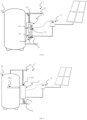
- the inlet connection 24 of the storage tank 2, 20 to the water supply may be connected to the lower hydraulic connection 22, and the outlet connection 25 from the storage tank 2, 20 may be connected to the upper hydraulic connection 23 as shown in Figure 1.a .
- the control unit 35 may comprise:
- the recirculation devices 34 comprise a pump 34 adapted to circulate a liquid coming from the lower hydraulic connection 22, 221, through the piping connection 33, from the inlet 331 to the outlet 332, and control devices may be provided for controlling the pump 34, said devices can be a control unit 35. According to some operating modes, a liquid may be conveyed from the lower hydraulic connection 22, 221, through the piping connection 33 by a pressure difference, which is therefore a recirculation device.
- the heating system 1 also comprises an outlet temperature sensor 38 configured to measure the water temperature at the outlet of the heating apparatus 3, 30, said water being able to be fed into the storage tank 2, 20 or sent to the water delivery point.
- an outlet temperature sensor 38 configured to measure the water temperature at the outlet of the heating apparatus 3, 30, said water being able to be fed into the storage tank 2, 20 or sent to the water delivery point.
- the outlet temperature sensor 38 is located in the heating apparatus 3, 30 in the proximity of the outlet end 332.
- the temperature measured by the outlet temperature sensor 38 is hereinafter referred to as outlet temperature T 38 .
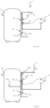
- Figures 1 and 2 show a heating apparatus 3 connected to the storage tank 2, 20, via hydraulic connections, while figures 3.a and 3.b show a heating apparatus 30 integrated into the storage tank 2, 20, for example fixed, internally or externally, to the walls of the casing of the storage tank 2, 20.
- Storage tank 2, 20, piping connection 33 and lower 22, and upper 23 hydraulic connections 221, 231 are configured so as to form a hydraulic circuit in which the water, under the action of a pressure difference or preferably of the pump 34, may be withdrawn from the lower portion of the storage tank 2, 20, heated in the piping connection 33, and sent to the upper hydraulic connection 23, 231 from which water may be fed to the use or into the upper portion of the storage tank 2, 20.
- the heating system 1 may comprise a non-return valve 4, arranged:
- a shut-off valve 8 may be provided on the branch of the lower hydraulic connection 22, 221 ( figure 2 ).
- the heating system 1 may comprise devices for varying the flow rate m of the water through the piping connection 33.
- the devices for varying the flow rate m of the water may be a controllable opening valve or even the same pump 34, which may be a variable flow rate or modulated revolution pump.
- the pump 34 may be part of the heating apparatus 3, 30 and the control unit 35 is configured to control the pump 34.
- the control unit 35 is capable of controlling the devices for varying the flow rate m.
- the heating system 1 comprises at least one lower temperature sensor 27, 37, capable of detecting the temperature of the water of the lower portion of the storage tank 2, 20 and of sending a measuring signal to the control unit 35.
- the temperature lower sensor 27, 37 may be positioned at any point in the lower portion of the storage tank 2, 20 and/or in the lower hydraulic connection 22, 221 and/or in the part of the piping connection 33 located between the heating element 32 and the inlet 331.
- the temperature lower sensor 27, 37 is located either in the lower portion of the storage tank 2, 20 ( Figure 1.a ) or in a part of the heating apparatus 3, 30 located between the heating element 32 and the inlet 331 of the piping connection 33 ( figure 1.c ).
- the heating system 1 may heat the water contained in the storage tank 2, 20 by means of the heating apparatus 3, 30. Under the action of a pressure difference, for example caused by the pump 34, the colder water is withdrawn from the lower portion of the storage tank 2, 20, is heated with the heating element 32, and is fed back into the upper portion of the storage tank 2, 20.
- a pressure difference for example caused by the pump 34
- thermocline of the temperatures in the storage tank 2, 20 is maintained, since water in the storage tank is heated with a substantially monotonically increasing temperature gradient from the engagement point of the lower hydraulic connection 22, 221 to the engagement point of the upper hydraulic connection 23, 231.
- the gradient may deviate from a monotonically increasing trend due to turbulences, in particular in transients following withdrawals and/or to the triggering of a recirculation motion, without this causing any such embodiment to depart from what is stated and claimed.
- the engagement point of the lower hydraulic connection 22, 221 is positioned substantially at the base of the storage tank 2, 20, for example it can coincide with the inlet connection 24 to the water supply ( Figure 1.a ) and preferably the engagement point of the upper hydraulic connection 23, 231 is positioned substantially at the top of the storage tank 2, 20, for example it can coincide with the outlet connection 25 towards the use ( Figure 1.a , 1.c ).
- part of the water that is heated in the piping connection 33 may come directly from the water supply and may be delivered directly to the use.
- the heating function may be activated to meet a self-consumption request or a demand response signal or a request for hot water.
- Six possible operating modes shall be described below, which are characterised by the reason for activation/deactivation, i.e. whether to meet a self-consumption request or a demand response signal or a request for hot water and based on whether or not a withdrawal occurs at the same time.
- the heating system 1 can receive power:
- the heating apparatus 3, 30, and preferably the control unit 35 is able to receive a signal containing at least the information relating to the fact that:
- control unit 35 If the control unit 35 is able to receive at least one signal indicative of a condition of overabundance of energy on the electricity grid, then the heating system 1 can operate in "Mode 1" for demand response.
- control unit 35 If the control unit 35 is able to detect and/or receive information relating to the surplus power from a renewable source and fed back into the grid, then the heating system 1 can also operate in "Mode 1" for self-consumption.
- Mode 1 self-consumption or demand response in the absence of withdrawal.
- the control unit 35 enters Mode 1 in the case of self-consumption when it detects that there is power from an available renewable source, which is equivalent to a local surplus power signal P sur or in case of demand response when it receives a signal of energy overabundance from the electricity grid.
- control unit 35 activates and keeps the heating element 32 and the pump 34 active until the outlet temperature T 38 reaches the surplus temperature T sur .
- control unit 35 regulates the power P to a value close to and less than or equal to the surplus power P sur .
- the heating system 1 is configured to vary the flow rate m
- the control unit 35 can be configured to regulate the flow rate m.
- the control unit 35 can regulate the flow rate m in a manner directly proportional to the power P, so as to maintain constant the increase in temperature of the water flowing through the piping connection 33.
- the flow rate m can be regulated to control the outlet temperature T 38 .
- the heating system 1 can be configured to vary the flow rate m of the liquid, as a function of the difference between a set temperature T target and a measured temperature of the water contained in the heating system 1 (or in the storage tank 2.20).
- the method for regulating the flow rate m may be defined as open loop or feedback.
- the flow rate m is controllable in a "feed forward" or open-loop control manner based on a requested temperature increase, ⁇ T, of the water at the outlet 332 with respect to the inlet 331 and the temperature of the water contained in the heating system 1 is a temperature measured upstream of the heating element 32.
- the heating system 1 has a lower temperature sensor 27, 37 configured to detect a temperature substantially equal to that of the water entering the heating system 3, 30 and/or equal to that of the water in the lower portion of the storage tank 2, 20, such temperature is indicated below as the lower temperature T inf .
- the lower temperature T inf cannot be detected with a specific sensor, this may be estimated: for the estimate, it is sufficient to activate the pump 34 without having activated the heating element 32 and detect the outlet temperature T 38 which, in the absence of heating, is approximately equal to the lower temperature T inf .
- T inf T inf + P m ⁇ c ⁇ T sur
- the power P is reduced and/or the flow rate m is increased. This allows to terminate smoothly the self-consumption mode while reducing the risk of a temperature overshoot.
- the control unit 35 may further reduce the temperature increase by lowering the power P to the maximum value that allows the surplus temperature T sur not to be exceeded at the output.
- the flow rate m control directly proportional to the power P, is a feed-forward type control and therefore less precise; however, high precision in controlling the temperature in the upper portion of the storage is not required. In fact, any temperature between the comfort temperature and the maximum temperature is acceptable for the device's purposes. Conversely, controlling the flow rate m to be directly proportional to the heating power P allows the heating to adapt to the surplus power Psur almost instantaneously, without delays caused by the typical reading times of any temperature sensor.
- feed-forward method of regulating the flow rate m it is possible to perform a feedback regulation on the flow rate m based on the value of the outlet temperature T 38 .
- a feedback control is advantageous because it makes the system robust with respect to errors, for example, errors in identifying the value of the flow rate m, which is typically known within an uncertainty range.
- the aim is to keep the outlet temperature T 38 less than or equal to the surplus temperature T sur , so it is very appropriate that the control unit 35 is configured to perform a feedback control on the flow rate m as a function of the outlet temperature T 38 .
- control unit 35 can be configured to calculate a flow rate variation ⁇ m, in order to maintain the outlet temperature T 38 close to the surplus temperature T sur , by performing a regulation of the flow rate m; this may be done, for example, by acting on the pump 34 or on the devices to vary the flow rate m.
- ⁇ m f T sur ⁇ T 38
- the function f represents a feedback control function and can comprise the proportional, derivative and/or integral components known to the man skilled in the art so that the control unit 35 reduces the flow rate m when the outlet temperature T 38 approaches the surplus temperature T sur .
- the self-consumption or demand response Mode 2 in presence of a withdrawal is described for the differences compared to the Mode 1 in absence of a withdrawal.
- the water in the heating system 3, 30 can come partly from the storage tank 2, 20 and partly from the water supply.
- self-consumption Mode 2 if the lower temperature sensor 27 is located inside the storage tank 2, 20 in the tank, the lower temperature T inf detected is different from the real water temperature in inlet 331 and is a value comprised between the temperature in the lower portion of the storage tank 2, 20 and that, generally lower, of the temperature of the water of the water supply.
- Mode 2 to obtain a better operation, it is preferable to use a lower temperature sensor 37 located at the inlet 331 of the heating apparatus 3, 30.
- the temperature T inf is generally overestimated.
- the flow rate set according to the formula m P ⁇ T ⁇ c ⁇ P sur ⁇ T ⁇ c is overestimated and the outlet temperature T 38 is therefore lower than the surplus temperature T sur .
- This error can be corrected with the feedback function in the flow control m.
- a mixing valve generally stabilises the temperature of the water outlet to the user; for example, if the outlet water from the heating system 1 has a higher temperature than that required by the user, the mixing valve reduces the flow rate of the water withdrawn from the outlet connection 25; the flow rate in the outlet connection 25 may be lower than the flow rate m through the heating apparatus, in this case a portion of the heated water is fed back into the storage tank 2, 20. Therefore, Mode 2, for the purposes of the ability of self-consuming or taking part to the demand response by storing energy, is based on the same control and in part provides substantially the same result in the case of withdrawal as in the case of no withdrawal of Mode 1.
- the activation and deactivation of the heating element 32 may cause sudden variations in the temperature at the outlet of the heating system 1, and even the presence of a mixing valve may not be able to compensate for them. Such sudden variations may entail the risk of scalding a user, reducing comfort and/or wasting the thermal energy that was intended to be stored.
- the control unit 35 is equipped to receive information from devices configured s to detect whether a withdrawal is in progress (described below). When it is in Mode 1 and a withdrawal is in progress, it switches to Mode 2. In Mode 2 the control unit 35, to avoid sudden changes in the temperature of the outlet water:
- control unit 35 To activate Mode 2 of self-consumption with a withdrawal in progress, the control unit 35 must be able to detect whether a withdrawal is in progress.
- the heating apparatus 3, 30 comprises devices 9, 35, 27, 37, 38, 34 to detect whether a withdrawal is in progress.
- a device for detecting whether a withdrawal is in progress may be a flow switch 9 (in figure 5 ); according to a possible embodiment, a flow switch 9 is inserted on the inlet connection 24 to the water supply or alternatively on the outlet connection 25. In this case, the control unit 35 is configured to receive a signal from the flow switch 9.
- the heating system 1 can comprise alternative devices are possible to detect whether a withdrawal is in progress, for example from a temperature sensor 27 located in the storage tank 2, 20.
- the control unit 35 can determine the start of a withdrawal from a sudden change, generally a decrease, of said temperature in the storage tank, and can determine the end of the same from an increase in said temperature.
- the control unit 35 activates the pump 34 without activating the heating element 32 and if it detects a water temperature lower than a preset expected value, it determines that a withdrawal is in progress.
- the control unit 35 can determine the end of the withdrawal if after an activation of the pump 34 it detects an increase in the water temperature.
- control unit 35 If the control unit 35 is not able to detect that a withdrawal is in progress, it cannot activate Mode 2 other than Mode 1; in this case, if the heating element 32 has variable power, then each activation and deactivation of the self-consumption and/or demand response function, even in Mode 1, occurs with a variation speed of the absorbed power P lower than a maximum comfort speed.
- the control unit 35 activates heating Mode 3 when it receives a signal indicating a temperature request, or when it detects that the water in the storage tank 2, 20 has a temperature lower than a set temperature T target . Since the water temperature in the storage tank 2, 20 is subject to an increasing gradient from bottom to top, the set temperature T target generally depends on the measurement point. In general, the set temperature T target may also vary based on the hourly program and/or the operating mode.
- the signal indicative of a temperature request may be:
- control unit 35 activates the heating element 32 and the pump 34.
- both the power P and the flow rate m are fixed and heating element 32 and pump 34 are both activated when there is a temperature request that can be according to any of the methods described.
- At least one of the flow rate m of the pump 34 and the power P of the heating element 32 is variable and is regulated with one or more proportional, derivative and/or integrative regulation functions.
- heating Mode 4 i.e. during a withdrawal, the heating function works as in absence of a withdrawal.
- the activation and/or deactivation of the heating element 32 during a withdrawal may cause sudden changes in the output temperature; however, since the heating element 32 is activated by a temperature request, it is necessary for it to be activated. Therefore, in heating Mode 3, the start of a withdrawal can be detected as in Mode 1. If a withdrawal is in progress the control unit 35 switches to Mode 4 and activates and/or deactivates the heating element 32 maintaining the variation speed of the power P lower than a predefined maximum comfort speed.
- a heating apparatus 3, 30 configured to operate in Modes 3 and 4 and heat even in absence of surplus power P sur , may be combined with a storage tank 2 otherwise devoid of own heating device.
- a heating apparatus 3, 30, configured to operate at least in Mode 1, can be combined with a storage water heater 20 to equip it with a self-consumption and/or demand response function.
- the storage tank 20 may be the tank of a water heater provided with its own heating elementss 202.
- An aspect of the present disclosure is a method for modifying a pre-existing gas or electric water heater 20 and equipping it with a self-consumption function.
- the method comprises the steps: providing the water heater 20 and a heating apparatus 3 comprising a piping connection 33 from an inlet 331 to an outlet 332, connecting the inlet 331 via a lower hydraulic connection 22, 221 to the lower portion of the storage tank 20 and connecting the outlet 332 via an upper hydraulic connection 23, 231 to the upper portion of the storage tank 20.
- the method comprises connecting the inlet 331 of the piping connection 33 to the inlet connection 24 to the water supply of the water heater 20 and connecting the outlet 332 of the piping connection 33 to the outlet connection 25.
- the temperature sensor 27, 37 is not an essential element of the heating system 1, since it is possible to measure the lower temperature also via the outlet temperature sensor 38 in a time interval in which the pump 34 has been active and the heating element 32 inactive.
- the heating system 1 comprising a water circulation system configured to draw water from the bottom of the tank, to heat it and to send back heated water to the top of the tank has several advantages versus a storage water heater of prior art: it has a substantially perfect thermocline since the temperature gradient in the storage tank 2, 20 is increasing from bottom to top, therefore the water at greater temperature is the first to be drawn and this allows to minimise the heat standing losses even versus vertical development water heaters, in which heating is entrusted to elements immersed in the storage tank or directly in contact with it.
- thermocline Water heaters solely equipped with heating elements configured to heat directly the water in a tank are subject to a trade-off between a thermocline, reachable only if water is heated from the top of the tank, and the need to heat a sufficient volume of water within the tank, satisfiable only by heating water from a bottom portion of the tank.
- Water heaters comprising a plurality of heating elements positioned at different heights in the tank partly address this problem without solving it.
- a thermocline allows hotter water to be drawn first, which, for any amount of thermal energy, all other conditions being the same, minimises heat standing losses. Minimising said losses is particularly advantageous where additional thermal energy is stored in order to use surplus power P sur .
- Instantaneous water heaters have substantially no heat standing losses.
- the heating system 1 according to at least some of the embodiments described adds some of the advantages of a storage water heater to an instantaneous water heater.
- the disclosure offers flexibility in setting the time for heating water, the power consumption event, which does not have to forcibly coincide with the hot water delivery event.
- the heating apparatus 3, 30 is configured to control the heating element 32 so as to follow the surplus power P sur and minimise the power fed into the electricity grid, or to respond to demand response signals.
- the activation of the heating element 32 can be independent of the water withdrawals.
- the heating function can be delegated in whole or in part to the heating apparatus 3, 30 that, unlike an element 202 inside the storage tank, has the possibility of supplying heated water starting from the top of the storage tank 2, 20.
- the heating system 1 is a storage water heater that comprises the storage tank 2, 20, optionally equipped with its own heating devices 202, and has the heating apparatus 30 integrated as in figure 3.a or 3.b .
- the heating apparatus 3, 30 can contribute in whole or in part to heating the storage tank 2, 20, which may or may not be equipped with its own heating elements 202; in this case the heating apparatus 3, 30 can be configured to provide a minimum amount of heat to the storage tank 2, 20 and possibly increase the consumption to cancel the surplus power P sur .
- the heating system 1 allows for controlling the amount of energy stored as thermal energy more precisely than the prior art.
- the temperature gradient from the point of withdrawal of the lower hydraulic connection 22, 221 to the inlet point of the upper hydraulic connection 23, 231 has a monotonically increasing trend. Knowing the temperature at two different heights, it is possible to estimate with precision and known methods the amount of thermal energy stored and therefore the volume of water that can be delivered for a given temperature of use.
- the heating apparatus 30 can be associated with a storage tank 2 and sold as an integrated product as in figure 3 ; alternatively, a storage tank 2, 20 and heating apparatus 3 can be a kit of single products.
- the heating system 1 can be assembled starting from a traditional storage water heater 20 and an instantaneous water heater equipped with a pump 34, preferably a variable flow pump 34.
- the heating system 1 can be obtained by modifying a previously installed storage water heater 20.
- Modes 5 and 6 make it possible to reduce consumptions without affecting comfort.
- the heating system 1 responds to a condition of energy scarcity by deactivating the heating elements 32, 202 until the user withdraws hot water.
- a heating system 1 must comprising devices 39, 41 configured to detect an upper water temperature, i.e. a temperature in the upper portion of the storage tank 2, 20, and devices 9, 35, 27, 37, 38, 34 configured to detect whether a withdrawal is in progress. Since the water temperature in the storage tank 2, 20 has a monotonous gradient increasing substantially from bottom to top, the upper temperature is understood to be the value detected by the upper temperature detection devices 39, 41.
- the devices 39, 41, for detecting a water temperature in the upper portion of the storage tank 2, 20 may be, by way of an example:
- the heating system 1 via the control unit 35, detects that a withdrawal is in progress and that the water temperature in the upper portion of the storage tank 2, 20 has a value lower than a minimum comfort temperature, such minimum temperature being a function of the set temperature T target , or a minimum factory value T min of a thermostatic valve 41.
- the control unit 35 activates the heating element 32 and possibly the pump 34 to supply heated water at a temperature higher than the minimum comfort temperature. Therefore, thanks to the presence of the heating apparatus 3, 30 that can function as an instantaneous heater, it is not necessary to maintain the water in the storage tank 2, 20 at a set temperature T target , nor at a minimum comfort temperature.
- the preferred embodiments are those in which the outlet 332 of the piping connection 33 is directly connected to the outlet connection 25 to the user(see e.g. Figures 1a , 1c , 2 , 3a , 3b , 5 ); in these embodiments the heating system 1 can function particularly effectively as an instantaneous water heater. In fact, it can receive water from the water supply, heat it and send it directly through the outlet connection 25 to the user without the need for the passage through a storage tank 2, 20, since heating can take place outside the storage tank 2, 20.
- the heating system 1 can be equipped with devices 41, 42 to limit the temperature of the water delivered to the outlet connection 25 at a lower and/or higher level.
- the heating system 1 can be equipped with devices 41, 42 configured to regulate the share of water flow coming from the storage tank 2, 20, versus that coming from the heating apparatus 3.
- a method is provided to regulate the outlet water temperature between the water temperature in the upper portion of the storage tank 2, 20 and the temperature at the outlet of the heating apparatus 3; therefore, it is possible to limit the temperature both above and below, in particular, it is possible to deliver water to the outlet pipe 25 at a temperature higher than the maximum temperature in the storage tank 2, 20.
- the upper branch 23' shall be referred to as the branch of the upper hydraulic connection 23 located between the outlet 10 of the storage tankand the connection with the outlet connection 25.
- the heating system 1 can comprise devices 41, 42 for regulating and/or interrupting the flow in the upper branch 23'.
- a device for regulating the water flows may be a mixing valve 41, preferably of the 3-way type, positioned at the intersection of the upper hydraulic connection 23 with the outlet connection 25, as in Figure 6a .
- the mixing valve 41 may be motorised and the heating system 1 may comprise an upper temperature sensor 39 positioned in the upper part of the storage tank 2, 20 or along the upper branch 23' i.e. between the outlet 10 of the storage tank 2, 20 and the mixing valve 41.
- An alternative device for regulating the water flows along the upper branch 23' may be a valve 42 positioned along the upper branch 23' as in Figure 6b , for example a "low-cut" thermostatic valve 42.
- a heating system 1 equipped with devices 41, 42 for regulating and/or interrupting the water flow along the upper branch 23' offers the additional benefit of being able to be used as an instantaneous heater without the need to activate recirculation devices such as the pump 34; in fact, during a withdrawal, water may flow through the piping connection 33, under the effect of the pressure difference that is created between the water supply pressure and the atmospheric pressure during a water withdrawal.
- the features illustrated in the embodiments are not necessarily available together. In other words, different embodiments may be imagined by the man skilled in the art, where not all of the illustrated features are jointly provided and/or implemented by the heating system 1.
- the embodiments available in each figure and/or in the description can be combined with the embodiments of one or more of any embodiments of any other figure and/or previously described.
- the retrofit method can be applied to any storage tank such as, for example, the storage tank of a gas or oil water heater.
- the heating apparatus control unit 35 maintains a minimum temperature set in the storage tank 2, 20, for example an average temperature and in addition performs the self-consumption and demand response functions.
- the heating system 1 finds application in the field of demand response being able to vary the electrical consumption based on external signals.
- the heating system 1 also finds application in the field of self-consumption, preferably in the version comprising a variable-power heating element 32.
Landscapes
- Engineering & Computer Science (AREA)
- Physics & Mathematics (AREA)
- General Engineering & Computer Science (AREA)
- Chemical & Material Sciences (AREA)
- Combustion & Propulsion (AREA)
- Mechanical Engineering (AREA)
- Thermal Sciences (AREA)
- Life Sciences & Earth Sciences (AREA)
- Sustainable Development (AREA)
- Sustainable Energy (AREA)
- Water Supply & Treatment (AREA)
- Fluid Mechanics (AREA)
- Heat-Pump Type And Storage Water Heaters (AREA)
Applications Claiming Priority (1)
| Application Number | Priority Date | Filing Date | Title |
|---|---|---|---|
| IT102023000025089A IT202300025089A1 (it) | 2023-11-27 | 2023-11-27 | Scaldaacqua ad accumulo a stratificazione perfezionata. |
Publications (1)
| Publication Number | Publication Date |
|---|---|
| EP4560221A1 true EP4560221A1 (fr) | 2025-05-28 |
Family
ID=89845231
Family Applications (1)
| Application Number | Title | Priority Date | Filing Date |
|---|---|---|---|
| EP24215253.6A Pending EP4560221A1 (fr) | 2023-11-27 | 2024-11-25 | Chauffe-eau à stratification améliorée |
Country Status (3)
| Country | Link |
|---|---|
| US (1) | US20250172298A1 (fr) |
| EP (1) | EP4560221A1 (fr) |
| IT (1) | IT202300025089A1 (fr) |
Citations (8)
| Publication number | Priority date | Publication date | Assignee | Title |
|---|---|---|---|---|
| EP2610999A2 (fr) | 2011-12-29 | 2013-07-03 | Werner Schmid | Procédé et dispositif de consommation d'énergie électrique d'une installation raccordée à un réseau domestique pour générer une énergie électrique renouvelable |
| EP3064858A1 (fr) * | 2015-03-06 | 2016-09-07 | Gebr. Tuxhorn GmbH & Co. KG | Systeme de chargement d'un ballon d'eau chaude |
| DE102016107627A1 (de) * | 2016-04-25 | 2017-10-26 | Oventrop Gmbh & Co. Kg | Anordnung zur Warmwasser- und Heizungswasser- Erzeugung unter mindestens teilweiser Nutzung von regenerativer elektrischer Energie |
| US20190293303A1 (en) * | 2018-03-20 | 2019-09-26 | Yanda Zhang | Intelligent hot water heating system with stratified temperature-heating control storage tank |
| EP3117158B1 (fr) | 2014-03-11 | 2020-01-22 | Electricité de France | Chauffe-eau électrique réglable en puissance |
| EP3662210B1 (fr) | 2017-08-01 | 2021-09-15 | Ariston Thermo S.P.A. | Procédé d'apprentissage de profil de prélèvements d'eau dans un chauffe-eau à accumulation |
| US11300325B2 (en) | 2017-09-19 | 2022-04-12 | A. O. Smith Corporation | System and method for operating a grid controlled water heater |
| US20230136851A1 (en) | 2021-11-03 | 2023-05-04 | Lunar Energy, Inc. | Retrofit hot water heat pump |
-
2023
- 2023-11-27 IT IT102023000025089A patent/IT202300025089A1/it unknown
-
2024
- 2024-11-21 US US18/954,723 patent/US20250172298A1/en active Pending
- 2024-11-25 EP EP24215253.6A patent/EP4560221A1/fr active Pending
Patent Citations (9)
| Publication number | Priority date | Publication date | Assignee | Title |
|---|---|---|---|---|
| EP2610999A2 (fr) | 2011-12-29 | 2013-07-03 | Werner Schmid | Procédé et dispositif de consommation d'énergie électrique d'une installation raccordée à un réseau domestique pour générer une énergie électrique renouvelable |
| EP3117158B1 (fr) | 2014-03-11 | 2020-01-22 | Electricité de France | Chauffe-eau électrique réglable en puissance |
| EP3064858A1 (fr) * | 2015-03-06 | 2016-09-07 | Gebr. Tuxhorn GmbH & Co. KG | Systeme de chargement d'un ballon d'eau chaude |
| EP3064858B1 (fr) | 2015-03-06 | 2018-12-19 | Gebr. Tuxhorn GmbH & Co. KG | Systeme de chargement d'un ballon d'eau chaude |
| DE102016107627A1 (de) * | 2016-04-25 | 2017-10-26 | Oventrop Gmbh & Co. Kg | Anordnung zur Warmwasser- und Heizungswasser- Erzeugung unter mindestens teilweiser Nutzung von regenerativer elektrischer Energie |
| EP3662210B1 (fr) | 2017-08-01 | 2021-09-15 | Ariston Thermo S.P.A. | Procédé d'apprentissage de profil de prélèvements d'eau dans un chauffe-eau à accumulation |
| US11300325B2 (en) | 2017-09-19 | 2022-04-12 | A. O. Smith Corporation | System and method for operating a grid controlled water heater |
| US20190293303A1 (en) * | 2018-03-20 | 2019-09-26 | Yanda Zhang | Intelligent hot water heating system with stratified temperature-heating control storage tank |
| US20230136851A1 (en) | 2021-11-03 | 2023-05-04 | Lunar Energy, Inc. | Retrofit hot water heat pump |
Also Published As
| Publication number | Publication date |
|---|---|
| US20250172298A1 (en) | 2025-05-29 |
| IT202300025089A1 (it) | 2025-05-27 |
Similar Documents
| Publication | Publication Date | Title |
|---|---|---|
| US10635120B2 (en) | Method for operating and/or monitoring an HVAC system | |
| US9063551B2 (en) | Adaptive heating control system for a water heater | |
| CA2784312C (fr) | Systeme de chauffe-eau sur demande | |
| AU2012262613B2 (en) | A water heater controller or system | |
| AU2010210842B2 (en) | Apparatus and control method for a hybrid tankless water heater | |
| CN112842073B (zh) | 液体加热器具及其控制方法、控制装置和可读存储介质 | |
| JP3912690B2 (ja) | 加熱水道水の温度制御方法並びに装置 | |
| CN107005061B (zh) | 电力管理系统 | |
| US20120054123A1 (en) | Hot water heater with an integrated flow meter | |
| KR20170105466A (ko) | 온수공급장치 및 온수공급방법 | |
| JP6044326B2 (ja) | 貯湯式給湯機及びソーラーシステム | |
| MX2008004033A (es) | Sistema y metodo para calentamiento mejorado de fluidos. | |
| EP3105511B1 (fr) | Nstallation d'eau chaude sanitaire | |
| RU2340835C2 (ru) | Автоматизированная информационная система для контроля и управления работой отопительной котельной с водогрейными котлами | |
| US11867429B2 (en) | Tankless water heater with integrated variable speed pump | |
| EP2966365B1 (fr) | Commande d'eau chaude | |
| EP4560221A1 (fr) | Chauffe-eau à stratification améliorée | |
| EP2492602B1 (fr) | Appareil et procédé pour optimiser le fonctionnement d'une chaudière pour chauffer l'eau | |
| US6415986B1 (en) | Heat supply system | |
| WO2022187253A1 (fr) | Procédé de commande de dispositif de chauffage | |
| CN119554785B (zh) | 一种储能换热用热水器及其控制方法和系统 | |
| EP4348127B1 (fr) | Chauffe-eau | |
| CA2753031C (fr) | Gestion de la demande de chauffe-eau | |
| US20120002955A1 (en) | Temperature control and power management control system for hydraulic heating systems | |
| EP1451505A1 (fr) | Procede et dispositif permettant de mesurer, reguler et enregistrer une quantite d'energie acheminee a un consommateur lors d'une distribution d'energie |
Legal Events
| Date | Code | Title | Description |
|---|---|---|---|
| PUAI | Public reference made under article 153(3) epc to a published international application that has entered the european phase |
Free format text: ORIGINAL CODE: 0009012 |
|
| STAA | Information on the status of an ep patent application or granted ep patent |
Free format text: STATUS: THE APPLICATION HAS BEEN PUBLISHED |
|
| AK | Designated contracting states |
Kind code of ref document: A1 Designated state(s): AL AT BE BG CH CY CZ DE DK EE ES FI FR GB GR HR HU IE IS IT LI LT LU LV MC ME MK MT NL NO PL PT RO RS SE SI SK SM TR |
|
| STAA | Information on the status of an ep patent application or granted ep patent |
Free format text: STATUS: REQUEST FOR EXAMINATION WAS MADE |
|
| 17P | Request for examination filed |
Effective date: 20251127 |