EP4560254A1 - Verfahren zur verbesserung eines schiesstrainings - Google Patents
Verfahren zur verbesserung eines schiesstrainings Download PDFInfo
- Publication number
- EP4560254A1 EP4560254A1 EP23307049.9A EP23307049A EP4560254A1 EP 4560254 A1 EP4560254 A1 EP 4560254A1 EP 23307049 A EP23307049 A EP 23307049A EP 4560254 A1 EP4560254 A1 EP 4560254A1
- Authority
- EP
- European Patent Office
- Prior art keywords
- target
- laser
- shooting device
- projectile
- shooting
- Prior art date
- Legal status (The legal status is an assumption and is not a legal conclusion. Google has not performed a legal analysis and makes no representation as to the accuracy of the status listed.)
- Pending
Links
Images


Classifications
-
- F—MECHANICAL ENGINEERING; LIGHTING; HEATING; WEAPONS; BLASTING
- F41—WEAPONS
- F41G—WEAPON SIGHTS; AIMING
- F41G3/00—Aiming or laying means
- F41G3/26—Teaching or practice apparatus for gun-aiming or gun-laying
- F41G3/2616—Teaching or practice apparatus for gun-aiming or gun-laying using a light emitting device
- F41G3/2622—Teaching or practice apparatus for gun-aiming or gun-laying using a light emitting device for simulating the firing of a gun or the trajectory of a projectile
- F41G3/2655—Teaching or practice apparatus for gun-aiming or gun-laying using a light emitting device for simulating the firing of a gun or the trajectory of a projectile in which the light beam is sent from the weapon to the target
-
- F—MECHANICAL ENGINEERING; LIGHTING; HEATING; WEAPONS; BLASTING
- F41—WEAPONS
- F41G—WEAPON SIGHTS; AIMING
- F41G3/00—Aiming or laying means
- F41G3/26—Teaching or practice apparatus for gun-aiming or gun-laying
- F41G3/2605—Teaching or practice apparatus for gun-aiming or gun-laying using a view recording device cosighted with the gun
-
- F—MECHANICAL ENGINEERING; LIGHTING; HEATING; WEAPONS; BLASTING
- F41—WEAPONS
- F41G—WEAPON SIGHTS; AIMING
- F41G3/00—Aiming or laying means
- F41G3/26—Teaching or practice apparatus for gun-aiming or gun-laying
- F41G3/2616—Teaching or practice apparatus for gun-aiming or gun-laying using a light emitting device
- F41G3/2622—Teaching or practice apparatus for gun-aiming or gun-laying using a light emitting device for simulating the firing of a gun or the trajectory of a projectile
- F41G3/2683—Teaching or practice apparatus for gun-aiming or gun-laying using a light emitting device for simulating the firing of a gun or the trajectory of a projectile with reflection of the beam on the target back to the weapon
- F41G3/2688—Teaching or practice apparatus for gun-aiming or gun-laying using a light emitting device for simulating the firing of a gun or the trajectory of a projectile with reflection of the beam on the target back to the weapon using target range measurement, e.g. with a laser rangefinder
-
- G—PHYSICS
- G09—EDUCATION; CRYPTOGRAPHY; DISPLAY; ADVERTISING; SEALS
- G09B—EDUCATIONAL OR DEMONSTRATION APPLIANCES; APPLIANCES FOR TEACHING, OR COMMUNICATING WITH, THE BLIND, DEAF OR MUTE; MODELS; PLANETARIA; GLOBES; MAPS; DIAGRAMS
- G09B9/00—Simulators for teaching or training purposes
- G09B9/003—Simulators for teaching or training purposes for military purposes and tactics
-
- F—MECHANICAL ENGINEERING; LIGHTING; HEATING; WEAPONS; BLASTING
- F41—WEAPONS
- F41G—WEAPON SIGHTS; AIMING
- F41G3/00—Aiming or laying means
- F41G3/26—Teaching or practice apparatus for gun-aiming or gun-laying
- F41G3/2616—Teaching or practice apparatus for gun-aiming or gun-laying using a light emitting device
- F41G3/2622—Teaching or practice apparatus for gun-aiming or gun-laying using a light emitting device for simulating the firing of a gun or the trajectory of a projectile
- F41G3/2644—Displaying the trajectory or the impact point of a simulated projectile in the gunner's sight
Definitions
- the present invention relates to a method and system for a shooting training of a shooting device on a target.
- the invention relates to a method and system used in live exercise shooting training or games.
- a technique most commonly used is the a posteriori observation of the accuracy of the shot. If the shot is fired at a target, then the target serves as a support for checking the accuracy of the shot fired. If the shot is fired at a target, then the accuracy of the shot is analyzed by way of the impact of the ammunition (blank or via a paintball for example). Another technique is to film the target via an external device allowing the user to check the accuracy of the shot.
- a last approach is to use a laser system coupled to the firing of the shot and analyzed by an external device, for example by means of multiple markers mounted on different parts of the potential targets which transmit the information to a central system whether there is an impact or not.
- EP 0985899 A1 proposes a compact device for recording video images which may be mounted on a gun and used to record video images before and after the firing of the gun.
- the recording device comprises a camera comprising a lens and a video image sensor.
- the video recording device is mounted on the gun such that the viewing area of the camera comprises the target area of the gun.
- the video image sensor generates an electronic signal representative of a video image impinging on the respective sensor.
- the output of the image sensor is processed and generally employed to produce successive frame data which are sequentially stored in locations of a semiconductor memory organized as a circular buffer memory while the video recording device is in an active state.
- additional frames are stored in the buffer memory for a short period of time and a portion of the buffer memory is employed to keep a video record of the shooting both before and after the event. Additional frames are successively stored in the unused portion of the buffer memory.
- US patent 8,022,986 by Jekel provides a shooting device orientation measurement device which comprises a processor configured to receive first location information indicative of the locations of a first and a second point on a shooting device, the first and second points being a known distance apart in a direction parallel to a pointing axis of the shooting device, and to receive second location information indicative of the locations of the first and second points on the shooting device.
- the processor is further configured to receive information indicative of a first terrestrial orientation and to determine a second terrestrial orientation corresponding to the shooting device based on the first and second location information and the information indicative of the first terrestrial orientation.
- the first location information represents a location relative to a first sensor at a first location and the second location information represents a location relative to a second sensor at a second location, and the first and second sensors are separated by a given distance.
- Patent application US 2012/0178053 A1 by D'Souza et al. relates to a method and system for a shooting training system which automatically predicts the ballistics based on automatically gathered meteorological and distance information.
- the projectile shooting training system also confirms that manual efforts performed by an operator to adjust the sight turrets would or would not result in hitting the target after firing a shot. Both adjustment of the turrets and target settings are used to distinguish between the following states after firing a shot: hit; kill; miss; near miss.
- a light or other signal is sent from the shooting device to the target to indicate that a shot was fired by the shooting device.
- the drawbacks of the existing methods are that, in general, shooting training requires an assessment of the shot fired to be provided in a way that is as close as possible to real ballistics while being free from the associated dangers.
- the analysis of a shot may be seen as a marking problem in which it is necessary to be able to label a target through certain opaque obstacles and fuzzy obstacles, or even via a curved trajectory.
- a method known for more than 20 years for tackling this problem consists in equipping the potential targets with photosensitive sensors that are able to send information when they are illuminated by a laser.
- This method has several drawbacks: attenuation of the laser over great distances, the inability to shoot through fuzzy obstacles (e.g. foliage), and the need to equip the target with enough photosensitive sensors, among others.
- the number of photosensitive sensors necessary engenders heavy weight that is not representative to real field equipment, as well as high cost. Additionally, laser light is emitted in a straight line, which does not precisely represent the trajectory of a projectile.
- a first aspect of the method comprises a method for improving a shooting training with a shooting device on a target, the shooting device comprises a laser having an initial position and the target comprising one or more laser receivers, the method comprising:
- the invention enables simultaneous and realistic estimation of the projectile trajectory, which engenders a more precise determination of the impact zone. Additionally, the system does not require placing a large number of sensors on users' equipment, which reduces the weight and therefore enable realistic training conditions, and reduces the costs.
- the invention enables using the laser for transmitting data instead of determining the impact zone, reducing the number of laser sensors.
- this mean of communication enables determining the position of the receiver target in the shooting device frame using the image analysis.
- this in turns enables communicating with the target by pointing the laser at it without knowing its "identification" or network address.
- the communication between the shooting device and the target using the laser enables lowering the cost and ensuring an effective use of bandwidth.
- the data is transmitted if the projectile hits the target.
- the shooting device comprises a trigger to shoot the projectile on the target, the acquisition of the image or video data being triggered when the trigger is activated.
- the steps of the method are performed automatically when a user pulls the trigger.
- the target is moving and the analysis step comprises: analyzing the motion of the target and determining a velocity of the target, and wherein the impact zone determination step comprises predicting the target position when the projectile reaches the target.
- the target is moving, it is possible to measure a future position of the target.
- the method comprises, acquiring further image or video data relating to the target prior to the step of transmitting data relating to the shot on the target.
- the further image or video data enable determining the kinematics of the target and thus its position at the transmitting time to ensure that the data relating to the shot is transmitted.
- the data relating to the shot on the target are chosen in a group consisting in a type of ammunition, identification information about a first user shooting the projectile, a time stamp and/or target coordinates and a combination thereof.
- the data relating to the shot can be further for training purpose, damage assessment on the target side and optional report to an exercise monitoring station.
- a second aspect of the invention provides a system for improving a shooting training with a shooting device on a target, the system comprising means to implement the method of any one of claims 1 to 6, the means comprising:
- the diameter of the laser is adjustable based on the analysis of the video of image data.
- a third aspect of the invention provides a computer program product, said computer program product comprising code instructions for performing, when executed by a processing unit, the steps of:
- the invention relates to a method 1000 for improving a shooting training with a shooting device on a target.
- Figure 1 represents a flow diagram of a method 1000 for improving a shooting training with a shooting device on a target, according to the invention.
- the shooting device W comprises a laser L having an initial position and the target T comprises one or more laser receivers R.
- the method 1000 may be used for live exercise training in which multiple players are training.
- the method 1000 may be used in a shooting game, such as a laser game.
- each user may hold a shooting device and be a target at the same time.
- some users may hold a shooting device and others may be a target.
- the target T corresponds to a user or a body area of a user.
- the shooting device W may be a firearm, such as a gun, that launches projectiles such as ammunitions or bullets.
- the device W is not required to fire any ammunition, the shot may be calculated virtually.
- the method 1000 comprises acquiring image or video data relating to the target.
- the shooting device W of a user may comprise a camera C which takes images and/or videos of a scene comprising another user.
- the camera C may be sensitive to infrared light in order to take images or videos in the dark.
- a first user U1 may hold a shooting device and aim an another user.
- the method 1000 is implemented by a system 100.
- the system 100 comprises means to implement the method 1000.
- the system 100 comprises the camera C comprised in the shooting device W of the first user U1 takes a photo and/or a video of a scene that comprises the second user U2, and therefore comprises the target T.
- the target T is a body area of the second user U2 which is in the field of view F of the camera C.
- the shooting device W comprises a trigger Trig to shoot a projectile on the target T.
- the acquisition of the image or video data being triggered when the trigger is activated.
- the photo and/or video is acquired automatically.
- the camera stream is activated as soon as the trigger Trig is activated, which is determined using an inertial measurement unit.
- the method comprises analyzing the acquired image or video data of the target T to determine pixels corresponding to at least one part of the target T.
- the analysis may comprise using a stance calculation algorithm based on neural networks.
- Figure 3 representing a schematic of a method for determining an impact zone of a shot from a shooting device W on a target T, according to an example.
- Figure 3 shows an example of an acquired image of the target T, i.e. the second user U2.
- the target T is detected by detecting the stance of the second user U2.
- the camera stream i.e. the acquired image or video data is processed either locally on the camera C or transmitted to a processing unit PU using a dedicated interface, such as Wi-Fi or USB (or similar) in order to extract the stance of the second user U2.
- the processing unit PU may be held by the first user U1 or be a dedicated service on a remote location serving as a computing node for multiple shooters.
- the camera C has previously been aligned and calibrated.
- a database may be used, the database listing standard distances between different body key points.
- a database such as the NASA Standard Human Body Model and the human body stance may be used.
- the method comprises determining a distance between the shooting device and the target based on the analysis and determining a position of one of the laser receivers.
- the standard distances between different body key points together with the camera parameters (such as the optical parameters of the lens) determined previously may be used to determine the body distance between the shooting device and the target T, i.e. the second user U2.
- the distance may be determined based on a GPS position of the users.
- each user may hold a GPS transmitter, for example comprised in the processing unit PU, which enables continuous tracking of the GPS position of each user.
- the first user U1 may hold a laser telemeter to detect the distance between the shooting device the second user U2.
- the distance is calculated per user and subsequent processing is performed on a user basis, then rejecting users that do not cross the ammunition's ballistic path.
- the method comprises shooting a virtual or a real projectile with the shooting device.
- the first user U1 may shoot blank ammunition, aiming at the target T, which is the second user U2 or a body area of the second user U2.
- the previous steps may be triggered when the first user U1 pulls the trigger Trigg.
- a non-lethal projectile may also be shot from the shooting device W. Therefore, the previous steps and the projectile being shot may be completed simultaneously.
- the method comprises determining the impact zone of the projectile on the target T by calculating a trajectory from the shooting device to the target T based on the distance determination and ballistic data from the projectile.
- the ballistic data may include the type of ammunition and the type of shooting device W.
- the trajectory of the projectile may be calculated by the processing unit PU of user U1 in which the ballistic data from the projectile are stored.
- the shooting device W and the ammunition used may be known, and therefore the ballistic properties.
- the projectile drop is calculated.
- the theoretical hit point is determined analogous to the dynamic hit determination.
- the processing unit PU of user U1 may calculate if the projectile has hit the target T, and/or which area of the target has been hit, corresponding to the impact zone on the target.
- the method 1000 comprises deflecting the laser L from the initial position to a new position based on the determined position of said one laser receiver.
- the method 1000 comprises transmitting with the laser at the new position to the laser receiver data relating to the determined impact zone and relating to the shot on the target.
- the processing unit PU of the user U1 calculates the position of the receiver of the second user U2 in the shooting device coordinates frame. Further, the processing unit PU then deflects the shooting device mounted steerable laser to aim at the target receiver. Data are then transmitted to the laser receiver of the second user U2 for further processing.
- each user may comprise a receiver R for receiving data relating to the shot.
- the data may include a type of ammunition, identification information about the first user U1 and/or the second user U2, a time stamp (when the trigger has been activated) and/or target coordinates (corresponding to the body area which has been hit).
- the transmitted data enable the second user U2 assessing damage locally and warning them that they have been hit.
- a light or a sound signal may be used to warn the user U2. Additional step may be taken like deactivating U2 shooting device.
- damage assessment information may be sent by the processing unit of the second user U2 to an exercise monitoring station for higher-level scenario control and later debriefing analysis.
- the target may comprise only one laser receiver R. for example on the helmet H.
- the target may comprise several receivers R.
- the processing unit PU may select one of the receivers.
- the processing Unit may select the receiver which is visible on the image or video data or randomly pick one of the receivers.
- the receiver R may be comprised in the processing unit PU or may be separate.
- the receiver R may be placed on the helmet of the second user U2 and the data may be transmitted via Bluetooth to the PU.
- the shooting device may comprise a laser L, and the data may be transmitted to the receiver R via a laser beam B.
- the laser beam B is deflected to aim at the receiver R in order to transmit the data.
- the shooting device W may comprise a system for deflecting the laser L, such as micro-electromechanical systems.
- the receiver R is placed in the field of view F of the camera C, which enables the deflection of the laser L.
- the image and/or video data may be analyzed to calculate the deflection of the laser needed to reach the receiver R.
- the method 1000 may further comprise: acquiring further image or video data relating to the target T prior to the step of transmitting data relating to the shot on the target T.
- the target T being hit by the projectile may engender a different position or stance of the second user U2.
- the second user U2 may fall on the ground or run away. Therefore, the position of the receiver R may be different from that at the time the image or video data was acquired.
- the diameter of the laser beam B may be adapted (increased or decreased) on the laser L depending on the estimated distance to enable close combat training, that is if several users are in the same area, or if the laser spot has an elliptical shape.
- the target T and the shooting device W may be moving.
- the second user U2 may be running. Therefore, in an example, the target T is moving and the analysis step may comprise: analyzing the motion of the target T and determining a velocity of the target T with respect to the shooting device coordinate frame, and wherein the impact zone determination step comprises predicting the target position when the projectile reaches the target T.
- the velocity may be determined by analyzing several images of the target and determining the position of a same spot of the target on the different images. Alternatively, the velocity may be determined from a video of the target.
- the tracking of the body stance of the user U2 enables determining the instantaneous velocity v human of the tracked user and its position in the immediate future in the potentially moving coordinate's frame of the shooting device. Using the determined velocity, the distance estimation between the shooting device W and the target T as well as the ballistic properties of the ammunition, the time delayed impact point may be calculated when shooting with lead.
- the data is transmitted if the projectile hits the target. For example, if the theoretical impact point coincides with the body, this information may be transmitted to the receiver R.
- the invention relates to a system 100 for improving a shooting training with a shooting device on a target.
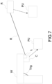
- Figure 7 illustrate a system 100 according to the invention.
- the system 100 is configured to implement the method 1000 described above.
- the system 100 comprises a shooting device W for shooting projectiles and comprising a camera C for acquiring image or video data relating to the target.
- the camera C may be sensitive to infrared light in order to be used at night or in dark conditions (for example, inside a building with no light).
- the shooting device W comprises a laser L having an initial position.
- the camera C may comprise a system for analysing the images or videos and therefore detect the stance of the second user U2. Therefore, the camera may be implemented using hardware, software, and/or a combination thereof in order to analyze the image and video data.
- the camera acquires the image and video data and transmits the data to a processing unit PU for further analysis.
- the camera may comprise a Bluetooth module to communicate with the processing unit PU.
- the camera C may transmit the image and video data to the processing unit PU via Bluetooth or local Wi-Fi.
- the camera C may comprise a power supply.
- WO 2020/079157 describes a camera that may be used.
- the camera C comprise a laser source L for transmitting data.
- the laser source L may use MEMS deflector and may be steerable to any position in the image.
- the system 100 further comprises one or more receivers for receiving the data relating to the determined impact zone and relating to the shot on the target.
- the shooting device further comprises a deflecting system configured to aim the laser at the one or more receivers.
- Figure 4a and Figure 4b show two examples of receivers R placed on a helmet H of a user, the receivers R being laser receivers.
- the receiver is placed on a harness which is placed on the helmet H.
- the harness enables to mount multiple laser receivers around the head to detect incoming signals coming from different directions.
- the receiver is placed on the top part of the helmet H. In that case, the laser receivers R may be able to detect a laser beam B with a 360-degree-angle. Therefore, the data may be transmitted even if the first user U1 is behind the second user U2.
- the system 100 comprises multiple receivers R.
- the system 100 may comprise one receiver which is placed on the helmet H of the user and a second receiver placed on the chest of the user. This is advantageous as it enables transferring data when several users are in close to each other or in case a particular sensor is hidden by any obstacle.
- the deflecting system comprises micro-electro-mechanical systems (MEMS).
- MEMS micro-electro-mechanical systems
- the diameter of the laser L is adjustable based on the analysis of the video of image data.
- the system 100 further comprises a processing unit PU - a processing unit comprising code instructions for analyzing the acquired image or video data of the target to determine pixels corresponding to at least one part of the target; for determining a distance between the shooting device and the target based on the analysis, determining a position of one of the laser receivers, for determining after a shooting of a projectile, the impact zone of the projectile on the target by calculating a trajectory from the shooting device on the target, based on the distance determination and ballistic data of the projectile deflecting the laser from the initial position to a new position based on the determined position of the of said one laser receiver; and transmitting with the laser at the new position to the laser receiver data relating to the determined impact zone and relating to the shot on the target.
- the processing unit PU of the first user U1 may comprise an artificial intelligence controller implementing image detection algorithms. Additionally, the processing unit PU of the second user U2 may comprise an acoustic indicator and an optical indicator or a vibration device to warn the second user U2 that they have been hit.
- the processing unit PU may be implemented using hardware, software, and/or a combination thereof.
- hardware devices may be implemented using processing circuity such as, but not limited to, a processor, Central Processing Unit (CPU), a controller, an arithmetic logic unit (ALU), a digital signal processor, a microcomputer, a field programmable gate array (FPGA), a System-on-Chip (SoC), a programmable logic unit, a microprocessor, or any other device capable of responding to and executing instructions in a defined manner.
- Software may include a computer program, program code, instructions, or some combination thereof, for independently or collectively instructing or configuring a hardware device to operate as desired.
- the computer program and/or program code may include program or computer-readable instructions, software components, software modules, data files, data structures, and/or the like, capable of being implemented by one or more hardware devices, such as one or more of the hardware devices mentioned above.
- a hardware device is a computer processing device (e.g. CPU, a controller, an ALU, a digital signal processor, a microcomputer, a microprocessor, etc.)
- the computer processing device may be configured to carry out program code by performing arithmetical, logical, and input/output operations, according to the program code.
- Each unit may also include one or more storage devices.
- the one or more storage devices may be tangible or non-transitory computer-readable storage media, such as random access memory (RAM), read only memory (ROM), a permanent mass storage device (such as a disk drive), solid state (e.g., NAND flash) device, and/or any other like data storage mechanism capable of storing and recording data.
- the one or more storage devices may be configured to store computer programs, program code, instructions, or some combination thereof, for one or more operating systems and/or for implementing the example embodiments described herein.
- the computer programs, program code, instructions, or some combination thereof may also be loaded from a separate computer readable storage medium into the one or more storage devices and/or one or more computer processing devices using a drive mechanism.
- Such separate computer readable storage medium may include a Universal Serial Bus (USB) flash drive, a memory stick, a Blu-ray/DVD/CD-ROM drive, a memory card, and/or other like computer readable storage media.
- USB Universal Serial Bus
- the processing unit PU may further comprise a Bluetooth and Wi-Fi module to receive the image and video data from the camera and the shot information from the laser receiver.
- the processing unit PU may further comprise a power supply.
- the processing unit PU may be a standard smartphone with graphic processing unit functionality.
- the phone may run an Android operating system.
- the processing unit PU may be a dedicated Linux platform.
- the processing unit may be the device for shot analysis described in WO 2020/079157 .
- the invention also concerns a computer program product, said computer program product comprising code instructions for performing, when executed by a processing unit, the steps of:
- the present description illustrates one embodiment of the invention, but is not limiting.
- the example was chosen to allow a good understanding of the principles of the invention, and one specific application, but it is not exhaustive, and the description should allow a person skilled in the art to provide modifications and implementation variants while keeping the same principles.
- the system has been implemented in the examples with one receiver placed on a helmet, the receiver may be placed on the chest for example or on any other body part of the users. Additionally, several receivers may be used.
- the invention has been illustrated in shooting training, the invention may also be used in games, such as laser game.
Landscapes
- Engineering & Computer Science (AREA)
- Radar, Positioning & Navigation (AREA)
- General Engineering & Computer Science (AREA)
- Theoretical Computer Science (AREA)
- Physics & Mathematics (AREA)
- Business, Economics & Management (AREA)
- Educational Administration (AREA)
- Educational Technology (AREA)
- General Physics & Mathematics (AREA)
- Optics & Photonics (AREA)
- Aiming, Guidance, Guns With A Light Source, Armor, Camouflage, And Targets (AREA)
Priority Applications (4)
| Application Number | Priority Date | Filing Date | Title |
|---|---|---|---|
| EP23307049.9A EP4560254A1 (de) | 2023-11-24 | 2023-11-24 | Verfahren zur verbesserung eines schiesstrainings |
| US18/954,370 US20250172370A1 (en) | 2023-11-24 | 2024-11-20 | Method for improving a shooting training |
| AU2024266770A AU2024266770A1 (en) | 2023-11-24 | 2024-11-21 | Method for improving a shooting training |
| CA3256678A CA3256678A1 (en) | 2023-11-24 | 2024-11-22 | Method for improving a shooting training |
Applications Claiming Priority (1)
| Application Number | Priority Date | Filing Date | Title |
|---|---|---|---|
| EP23307049.9A EP4560254A1 (de) | 2023-11-24 | 2023-11-24 | Verfahren zur verbesserung eines schiesstrainings |
Publications (1)
| Publication Number | Publication Date |
|---|---|
| EP4560254A1 true EP4560254A1 (de) | 2025-05-28 |
Family
ID=89843526
Family Applications (1)
| Application Number | Title | Priority Date | Filing Date |
|---|---|---|---|
| EP23307049.9A Pending EP4560254A1 (de) | 2023-11-24 | 2023-11-24 | Verfahren zur verbesserung eines schiesstrainings |
Country Status (4)
| Country | Link |
|---|---|
| US (1) | US20250172370A1 (de) |
| EP (1) | EP4560254A1 (de) |
| AU (1) | AU2024266770A1 (de) |
| CA (1) | CA3256678A1 (de) |
Citations (5)
| Publication number | Priority date | Publication date | Assignee | Title |
|---|---|---|---|---|
| EP0985899A1 (de) | 1998-09-09 | 2000-03-15 | Mitsubishi Denki Kabushiki Kaisha | Videorecorder für eine Zielwaffe |
| US8022986B2 (en) | 2009-05-19 | 2011-09-20 | Cubic Corporation | Method and apparatus for measuring weapon pointing angles |
| US20120178053A1 (en) | 2008-03-13 | 2012-07-12 | Cubic Corporation | Sniper training system |
| US8400619B1 (en) * | 2008-08-22 | 2013-03-19 | Intelligent Automation, Inc. | Systems and methods for automatic target tracking and beam steering |
| WO2020079157A1 (fr) | 2018-10-18 | 2020-04-23 | Thales | Dispositif et procede d'analyse de tir |
-
2023
- 2023-11-24 EP EP23307049.9A patent/EP4560254A1/de active Pending
-
2024
- 2024-11-20 US US18/954,370 patent/US20250172370A1/en active Pending
- 2024-11-21 AU AU2024266770A patent/AU2024266770A1/en active Pending
- 2024-11-22 CA CA3256678A patent/CA3256678A1/en active Pending
Patent Citations (6)
| Publication number | Priority date | Publication date | Assignee | Title |
|---|---|---|---|---|
| EP0985899A1 (de) | 1998-09-09 | 2000-03-15 | Mitsubishi Denki Kabushiki Kaisha | Videorecorder für eine Zielwaffe |
| US20120178053A1 (en) | 2008-03-13 | 2012-07-12 | Cubic Corporation | Sniper training system |
| US8400619B1 (en) * | 2008-08-22 | 2013-03-19 | Intelligent Automation, Inc. | Systems and methods for automatic target tracking and beam steering |
| US8022986B2 (en) | 2009-05-19 | 2011-09-20 | Cubic Corporation | Method and apparatus for measuring weapon pointing angles |
| WO2020079157A1 (fr) | 2018-10-18 | 2020-04-23 | Thales | Dispositif et procede d'analyse de tir |
| US20210372738A1 (en) * | 2018-10-18 | 2021-12-02 | Thales | Device and method for shot analysis |
Also Published As
| Publication number | Publication date |
|---|---|
| US20250172370A1 (en) | 2025-05-29 |
| AU2024266770A1 (en) | 2025-06-12 |
| CA3256678A1 (en) | 2025-10-30 |
Similar Documents
| Publication | Publication Date | Title |
|---|---|---|
| US10584940B2 (en) | System and method for marksmanship training | |
| US11015902B2 (en) | System and method for marksmanship training | |
| US10539393B2 (en) | System and method for shooting simulation | |
| US10274287B2 (en) | System and method for marksmanship training | |
| US8459997B2 (en) | Shooting simulation system and method | |
| KR101211100B1 (ko) | 선도 사격을 모사하는 화기 모사 시스템 및 레이저 발사 장치 | |
| US10234240B2 (en) | System and method for marksmanship training | |
| US8888491B2 (en) | Optical recognition system and method for simulated shooting | |
| US20210372738A1 (en) | Device and method for shot analysis | |
| US8678824B2 (en) | Shooting simulation system and method using an optical recognition system | |
| WO2012135352A2 (en) | Lidar methods and apparatus | |
| US12305961B2 (en) | Device and method for shot analysis | |
| US11359887B1 (en) | System and method of marksmanship training utilizing an optical system | |
| KR20090034156A (ko) | 곡사화기 모의 훈련 장치 및 방법 | |
| EP4560254A1 (de) | Verfahren zur verbesserung eines schiesstrainings | |
| CN117073456B (zh) | 一种火炮模拟训练设备、系统及模拟训练方法 | |
| EP1870661A1 (de) | Simulationssystem und -verfahren zur Bestimmung der Kompasspeilung von Zielvorrichtungen einer virtuellen Schusseinrichtung für Geschosse oder Flugkörper | |
| KR101241283B1 (ko) | 선도 사격을 모사하는 화기 모사 시스템 및 표적 감지 장치 | |
| JPH11142098A (ja) | 投下爆弾の着弾位置検出方法及び装置 | |
| IL300923B2 (en) | Combat training system | |
| US11662178B1 (en) | System and method of marksmanship training utilizing a drone and an optical system | |
| WO1998049514A2 (en) | System and method for enabling digital pursuit of natural and artificial targets | |
| KR20200008776A (ko) | 레이더 전자사격 시스템 | |
| US12253337B2 (en) | Hybrid tactical engagement simulation system | |
| GB2643209A (en) | Anti-drone firearm use training system |
Legal Events
| Date | Code | Title | Description |
|---|---|---|---|
| PUAI | Public reference made under article 153(3) epc to a published international application that has entered the european phase |
Free format text: ORIGINAL CODE: 0009012 |
|
| STAA | Information on the status of an ep patent application or granted ep patent |
Free format text: STATUS: THE APPLICATION HAS BEEN PUBLISHED |
|
| AK | Designated contracting states |
Kind code of ref document: A1 Designated state(s): AL AT BE BG CH CY CZ DE DK EE ES FI FR GB GR HR HU IE IS IT LI LT LU LV MC ME MK MT NL NO PL PT RO RS SE SI SK SM TR |
|
| STAA | Information on the status of an ep patent application or granted ep patent |
Free format text: STATUS: REQUEST FOR EXAMINATION WAS MADE |
|
| 17P | Request for examination filed |
Effective date: 20251031 |
|
| GRAP | Despatch of communication of intention to grant a patent |
Free format text: ORIGINAL CODE: EPIDOSNIGR1 |
|
| STAA | Information on the status of an ep patent application or granted ep patent |
Free format text: STATUS: GRANT OF PATENT IS INTENDED |