EP4560302A1 - Dispositif de mesure de gaz et procédé de mesure de gaz pour un gaz cible avec compensation améliorée d'une condition environnementale - Google Patents
Dispositif de mesure de gaz et procédé de mesure de gaz pour un gaz cible avec compensation améliorée d'une condition environnementale Download PDFInfo
- Publication number
- EP4560302A1 EP4560302A1 EP24212102.8A EP24212102A EP4560302A1 EP 4560302 A1 EP4560302 A1 EP 4560302A1 EP 24212102 A EP24212102 A EP 24212102A EP 4560302 A1 EP4560302 A1 EP 4560302A1
- Authority
- EP
- European Patent Office
- Prior art keywords
- measuring device
- gas
- mode
- detector
- compensator
- Prior art date
- Legal status (The legal status is an assumption and is not a legal conclusion. Google has not performed a legal analysis and makes no representation as to the accuracy of the status listed.)
- Pending
Links
Images


Classifications
-
- G—PHYSICS
- G01—MEASURING; TESTING
- G01N—INVESTIGATING OR ANALYSING MATERIALS BY DETERMINING THEIR CHEMICAL OR PHYSICAL PROPERTIES
- G01N33/00—Investigating or analysing materials by specific methods not covered by groups G01N1/00 - G01N31/00
- G01N33/0004—Gaseous mixtures, e.g. polluted air
- G01N33/0006—Calibrating gas analysers
-
- G—PHYSICS
- G01—MEASURING; TESTING
- G01N—INVESTIGATING OR ANALYSING MATERIALS BY DETERMINING THEIR CHEMICAL OR PHYSICAL PROPERTIES
- G01N25/00—Investigating or analyzing materials by the use of thermal means
- G01N25/20—Investigating or analyzing materials by the use of thermal means by investigating the development of heat, i.e. calorimetry, e.g. by measuring specific heat, by measuring thermal conductivity
- G01N25/22—Investigating or analyzing materials by the use of thermal means by investigating the development of heat, i.e. calorimetry, e.g. by measuring specific heat, by measuring thermal conductivity on combustion or catalytic oxidation, e.g. of components of gas mixtures
- G01N25/28—Investigating or analyzing materials by the use of thermal means by investigating the development of heat, i.e. calorimetry, e.g. by measuring specific heat, by measuring thermal conductivity on combustion or catalytic oxidation, e.g. of components of gas mixtures the rise in temperature of the gases resulting from combustion being measured directly
- G01N25/30—Investigating or analyzing materials by the use of thermal means by investigating the development of heat, i.e. calorimetry, e.g. by measuring specific heat, by measuring thermal conductivity on combustion or catalytic oxidation, e.g. of components of gas mixtures the rise in temperature of the gases resulting from combustion being measured directly using electric temperature-responsive elements
-
- G—PHYSICS
- G01—MEASURING; TESTING
- G01N—INVESTIGATING OR ANALYSING MATERIALS BY DETERMINING THEIR CHEMICAL OR PHYSICAL PROPERTIES
- G01N27/00—Investigating or analysing materials by the use of electric, electrochemical, or magnetic means
- G01N27/02—Investigating or analysing materials by the use of electric, electrochemical, or magnetic means by investigating impedance
- G01N27/04—Investigating or analysing materials by the use of electric, electrochemical, or magnetic means by investigating impedance by investigating resistance
- G01N27/14—Investigating or analysing materials by the use of electric, electrochemical, or magnetic means by investigating impedance by investigating resistance of an electrically-heated body in dependence upon change of temperature
- G01N27/16—Investigating or analysing materials by the use of electric, electrochemical, or magnetic means by investigating impedance by investigating resistance of an electrically-heated body in dependence upon change of temperature caused by burning or catalytic oxidation of surrounding material to be tested, e.g. of gas
-
- G—PHYSICS
- G01—MEASURING; TESTING
- G01N—INVESTIGATING OR ANALYSING MATERIALS BY DETERMINING THEIR CHEMICAL OR PHYSICAL PROPERTIES
- G01N33/00—Investigating or analysing materials by specific methods not covered by groups G01N1/00 - G01N31/00
- G01N33/0004—Gaseous mixtures, e.g. polluted air
- G01N33/0009—General constructional details of gas analysers, e.g. portable test equipment
- G01N33/0027—General constructional details of gas analysers, e.g. portable test equipment concerning the detector
Definitions
- the invention relates to a gas measuring device and a gas measuring method which are capable of measuring the concentration of a target gas and can be operated in different modes, wherein in each mode the influence of a non-directly measured ambient condition on a detection variable is well compensated and wherein it depends on the mode which ambient condition is compensated.
- the invention applies a principle known from the prior art, also known as a "catalytic catalytic sensor.”
- the target gas is combustible, meaning it can be oxidized.
- a detector is heated and heats a gas sample in a measuring chamber. The heating of the gas sample leads to the oxidation of combustible target gas in the gas sample. The oxidation releases heat energy. The released heat energy further heats the detector, and a detector detection variable that correlates with the detector temperature is measured. The further heating and thus the detector detection variable correlate with the desired concentration of combustible target gas.
- Further heating of the detector depends not only on the target gas concentration but also on ambient conditions. It is also known from the prior art to use a compensator that oxidizes less or no target gas at all, but ideally reacts to ambient conditions in the same way as the detector. A detection variable of the compensator is measured and used to compensate for the influence of ambient conditions on the detector's detection variable.
- the invention can also be applied to a gas measuring device that uses a different principle to measure the concentration of a target gas, in particular an optical measuring method with a radiation source and a photodetector (absorption spectroscopy) or an acoustic measuring method with a radiation source or sound source and an acoustic sensor or an electrochemical measuring method.
- a gas measuring device that uses a different principle to measure the concentration of a target gas, in particular an optical measuring method with a radiation source and a photodetector (absorption spectroscopy) or an acoustic measuring method with a radiation source or sound source and an acoustic sensor or an electrochemical measuring method.
- the invention is based on the object of providing a gas measuring device and a gas measuring method which are capable of measuring the concentration of a target gas and of compensating for the influence of an ambient condition on the measurement results better than known gas measuring devices and gas measuring methods, without necessarily requiring a sensor for these ambient conditions.
- gas measuring device having the features of claim 1 and by a gas measuring method having the features of claim 12.
- gas measuring method having the features of claim 12.
- Advantageous embodiments of the gas measuring device according to the invention are, to the extent appropriate, also advantageous embodiments of the gas measuring method according to the invention and vice versa.
- the gas measuring device is capable of measuring the concentration of at least one target gas in a spatial area.
- the target gas is a flammable target gas; in another application, it is another target gas harmful to humans.
- the target gas can also be a gas essential to human life, such as oxygen, carbon dioxide, or an anesthetic.
- the gas measuring device typically only provides at least an estimated value (approximate value) for the actual target gas concentration, although the estimated value may differ from the actual value.
- the gas measuring method according to the invention is carried out automatically using a gas measuring device according to the invention.
- a gas sample flows from the area to be monitored into the interior of the gas measuring device, where it reaches both a detector and a compensator of the gas measuring device.
- a fluid delivery unit of the gas measuring device draws in the gas sample; in another embodiment, the gas sample diffuses into the interior.
- the detector has a measurable detector detection quantity, e.g., electrical voltage or current. This detector detection quantity correlates with the concentration of the target gas in a gas sample.
- a detector detection quantity sensor of the gas measuring device is capable of measuring the detector detection quantity.
- a sensor measures a physical quantity means the following: The sensor directly measures the physical quantity or another physical quantity that correlates with the quantity being measured and is therefore a measure of the quantity being measured.
- a detection quantity is, for example, the temperature of a conductive component, and the sensor measures the electrical voltage and/or the electrical current.
- the gas sample originates from a spatial area to be monitored. Ambient conditions, particularly the ambient temperature, in this spatial area affect the gas sample. As a rule, the detector detection variable is therefore inevitably influenced by at least one environmental condition, particularly the ambient temperature. The compensator detection variable is also influenced by this environmental condition. However, the compensator detection variable correlates less with the target gas concentration than the detector detection variable and, in one embodiment, does not depend significantly on the target gas concentration. Ideally, both detection variables—optionally after a zero value correction—depend equally on all environmental conditions. In practice, this ideal situation is generally unattainable.
- a signal-processing evaluation unit can automatically determine the concentration of the target gas in the gas sample. To determine this, the evaluation unit uses the measured detector detection quantity (i.e., a signal from the detector detection quantity sensor), the measured compensator detection quantity (i.e., a signal from the compensator detection quantity sensor), and—if present—a signal from an optional sensor for an ambient condition. It is possible for the evaluation unit to use the respective signal from at least two ambient condition sensors.
- the step in which the evaluation unit determines the target gas concentration can also be described as a process in which the evaluation unit calculates an estimate of the actual target gas concentration. This step therefore at least approximately measures the actual target gas concentration.
- the determined target gas concentration therefore depends on both the detector detection variable and the compensator detection variable.
- the compensator detection variable allows for computational compensation, to a certain extent, for the influence of the ambient temperature and the influence of at least one other environmental condition on the detector detection variable.
- a total detection variable is calculated by applying a functional relationship, which preferably comprises a weighted average of the measured detector detection variable and the measured compensator detection variable.
- the target gas concentration is determined as a function of the total detection variable.
- the gas measuring device does not provide the actual target gas concentration as the measurement result, but rather an estimated value for the target gas concentration.
- the "measurement result of the gas measuring device" or the "determined target gas concentration” is referred to, whereby the determined target gas concentration usually deviates from the actual target gas concentration.
- the determined target gas concentration should deviate relatively little from the actual target gas concentration. How this is achieved according to the invention is described below.
- the detector detection variable and thus the signal of the detector detection variable sensor depend on the one hand on the desired target gas concentration and on the other hand on three environmental conditions: the ambient temperature, the ambient humidity, and the ambient pressure.
- the gas measuring device according to the invention can comprise a sensor for one environmental condition.
- the compensator detection variable and thus the signal of the compensator detection variable sensor also depend on these three environmental conditions.
- the invention shows a way of taking the respective influence of these three environmental conditions into account without the gas measuring device necessarily having to have a sensor for each environmental condition.
- the gas detection device can be operated in at least one of at least two different modes.
- One of these modes is a pressure-compensated mode, and one or more of these modes is a humidity-compensated mode.
- the gas detection device is operated in at least one mode and in exactly one mode at any given time. It is possible for it to be operated in two different modes during a deployment or during two consecutive deployments.
- the characteristic that an ambient condition is compensated cannot usually be fully achieved.
- the formulation that an ambient condition is compensated means the following: The ambient condition is compensated at least to a certain extent.
- the formulation that an ambient condition is compensated preferably means the following:
- the gas measuring device is calibrated. For this calibration, a sample with several sample elements is used. Each sample element contains the target gas with a known target gas concentration. The gas measuring device measures the respective target gas concentration of each sample element under known ambient conditions. During calibration, the gas measuring device is calibrated so that the following result is achieved: When applied to the sample, the influence of the ambient pressure (pressure-compensating mode) or the influence of the ambient humidity (humidity-compensating mode) is compensated as best as possible.
- the formulation that a boundary condition is met means that this boundary condition is met when the gas measuring device is applied to the sample.
- the gas measuring device is calibrated in such a way that the influence of the ambient pressure (pressure-compensating mode) or the influence of the ambient humidity (humidity-compensating mode) is compensated as best as possible while maintaining the boundary condition.
- the gas detection device is not necessarily able to optimally compensate for an environmental condition, especially not necessarily optimally for every possible combination of environmental conditions.
- a boundary condition is also not necessarily met for every possible combination of environmental conditions.
- the determined target gas concentration depends in a first way on the detector detection variable and the compensator detection variable, and in humidity-compensated mode, in a second way. These two modes differ from each other.
- the determined target gas concentration depends on a weighted average of the two detection variables, with at least one weighting factor being different for one mode than the other.
- the evaluation unit determines the target gas concentration as a function of an overall detection variable, wherein the overall detection variable is calculated by applying a functional relationship to the two individual detection variables, and wherein the functional relationship comprises a weighted average of the detector detection variable and the compensator detection variable.
- this functional relationship depends differently on the detector detection variable and/or the compensator detection variable than in humidity-compensating mode.
- the weighting factor with which the detector detection variable is incorporated into the functional relationship and/or the weighting factor of the compensator detection variable differ from mode to mode.
- the gas measuring device can be operated in at least one of at least two different modes. In one embodiment, it can be operated in at least one of four different modes, namely, additionally, in a pressure-optimized and/or a humidity-optimized mode.
- the pressure-optimized mode the influence of the ambient pressure on the evaluation unit's determination result is compensated for as best as possible, i.e., without a boundary condition relating to another ambient condition.
- the humidity-optimized mode the influence of ambient humidity on the determination result is compensated for as best as possible, i.e. without observing a boundary condition regarding another ambient condition.
- the at least two different modes allow the gas measuring device to be adapted to specific operating conditions and to specific requirements regarding the accuracy of the measurement results.
- the ambient pressure is expected to fluctuate significantly during an application, while the ambient humidity remains approximately constant.
- This operating condition occurs, for example, when the target gas concentration is measured in a pipe with a gas mixture flowing through it.
- the pressure of the gas mixture in the pipe can fluctuate significantly. Therefore, for this application, the gas measuring device is preferably operated in pressure-compensated or even in the optional pressure-optimized mode.
- the gas measuring device is preferably operated in humidity-compensated or even in the optional humidity-optimized mode.
- This operating condition occurs, for example, when the target gas concentration is measured in a completely or at least largely enclosed space, such as a measuring chamber or container.
- the invention eliminates the need to compromise, allowing the gas measuring device to be used unchanged and without adjustment for every possible operating condition. This compromise may result in the device not providing a sufficiently accurate measurement result under certain operating conditions.
- the invention can be used in combination with at least one sensor for an environmental condition.
- the invention eliminates the need for the gas measuring device to include a sufficiently reliable sensor for each environmental condition that influences or could influence the detection result, i.e., a temperature sensor, a humidity sensor, and a pressure sensor.
- the invention also eliminates the need to receive and process a signal containing information about an environmental condition from a spatially distant sensor.
- the environmental conditions at the measuring position of this spatially distant sensor can differ significantly from the environmental conditions at the measuring position of the gas measuring device according to the invention.
- the gas measuring device can be selectively operated in any of at least two, optionally four, different modes.
- the setting of the mode in which the gas measuring device is operated is carried out exclusively by adapting the evaluation unit, i.e., generally by adapting the software.
- at least one calculation rule used by the evaluation unit to determine the estimated target gas concentrations by evaluating signals is adapted accordingly to the respective mode.
- the hardware can in many cases remain the same for every possible mode in which the gas measuring device is or can be used.
- this feature makes it easier to implement the invention on an existing gas measuring device.
- this feature makes it possible to manufacture several identical gas measuring devices and then configure each of these identical devices for the respective mode. This approach is in many cases more reliable, particularly due to the possibility of series production, than using gas measuring devices with different hardware components for the different modes.
- a gas measuring device it is possible for a gas measuring device according to the invention to be adapted to a mode in advance, i.e. during calibration and/or adjustment of the gas measuring device. It is possible for the gas measuring device to then only be usable in this mode.
- the gas measuring device additionally comprises a selection unit. A user or a higher-level controller selects one of the at least two different possible modes with the aid of this selection unit. The gas measuring device is then operated in this mode. The user or the controller can later select a different mode with the aid of the selection unit.
- This embodiment makes it possible to use the same gas measuring device to be used successively for different operating conditions without having to replace any component of the gas measuring device.
- the gas measuring device prefferably switch from one mode to another and to measure an estimated value for the target gas concentration in at least two different modes, preferably in every possible mode, one after the other.
- the gas measuring device additionally comprises at least one sensor for an ambient condition, in particular a temperature sensor.
- the temperature sensor of the gas measuring device is capable of measuring a temperature in the environment of the gas measuring device.
- the evaluation unit of the gas measuring device additionally uses a signal from the or each sensor for an ambient condition, for example, a signal containing information about the measured ambient temperature. It is possible for the gas measuring device to comprise one sensor for at least two ambient conditions, and for the evaluation unit to use two signals from these two sensors to determine the target gas concentration. Thanks to the invention, however, it is not necessary for the gas measuring device to comprise one sensor for each relevant ambient condition.
- the gas measuring device comprises a temperature sensor, but neither a sensor for the ambient humidity nor a sensor for the ambient pressure.
- a temperature sensor can be chemically and mechanically separated. Thermal contact is usually sufficient.
- a sensor for an ambient condition can be selectively activated or deactivated, for example, manually by a user or automatically by a control unit of the gas measuring device, wherein this sensor belongs to the gas measuring device.
- the control unit or a user deactivates a sensor for an ambient condition if it has been determined or decided that this sensor is defective.
- the fact that a sensor for an ambient condition is defective can be recognized in particular by a measured value from the sensor that lies outside a value range for the ambient condition that occurs in practice.
- a user or the control unit may deactivate a sensor for an environmental condition if the gas detection device is intended to be used in an environment that is or could be harmful to that sensor, or if that sensor consumes a lot of electrical power or is unable to provide a reliable measurement of the environmental condition in that environment.
- the gas detection device includes a temperature sensor that is permanently active, as well as a pressure sensor and/or a humidity sensor that is selectively activated or deactivated.
- the gas measuring device comprises a sensor for each relevant ambient condition, i.e. in particular a sensor for the ambient temperature, for the ambient humidity, and for the ambient pressure.
- a sensor for each relevant ambient condition i.e. in particular a sensor for the ambient temperature, for the ambient humidity, and for the ambient pressure.
- Each of these sensors can be activated and deactivated, preferably independently of any other sensor.
- a user can selectively activate or deactivate each sensor for an ambient condition.
- the embodiment in which the gas measuring device comprises a sensor for each relevant ambient condition makes it easier to produce several gas measuring devices according to the invention. These gas measuring devices all have the same hardware and in particular comprise the sensors for the ambient conditions. In order to determine a specific To adapt a gas detection device, it is sufficient to enable or disable individual sensors. It is not necessary to manufacture gas detection devices with different hardware.
- the gas measuring device can be operated selectively in a mode selection state in which at least one of the two to four inventive or optional modes can be selected and applied, or in a standard state in which the evaluation unit determines the target gas concentration independently of a mode or in a default mode or in which the gas measuring device measures the target gas concentration successively in each mode, i.e. automatically switches from one mode to another.
- the design with these two states can be combined with the design in which at least one sensor for an environment is optionally activated or deactivated.
- the gas measuring device comprises a pressure sensor that is optionally activated or deactivated.
- the evaluation unit uses the signal from the pressure sensor to take into account the influence of the ambient pressure on the determination of the target gas concentration.
- the gas measuring device is operated at least temporarily in pressure-compensated mode. The same applies to a humidity sensor and the humidity-compensated mode.
- the gas measuring device can, for example, measure every ambient condition relevant to the measurement result. The corresponding sensor is therefore present and activated.
- the gas measuring device is designed as a so-called catalytic converter.
- the detector comprises a heatable detector segment, and the gas measuring device is capable of heating the detector segment.
- the gas measuring device is capable of applying an electrical voltage to the detector segment, and the then flowing current heats the detector segment.
- the heated detector segment oxidizes combustible target gas that has reached the detector as part of the gas sample—of course, only if this gas sample contains a sufficient amount of combustible
- the oxidation of the target gas releases heat energy, and this released heat energy increases the temperature of the detector segment.
- the temperature of the detector segment thus correlates with the target gas concentration.
- the compensator comprises a heatable compensator segment.
- the gas measuring device is capable of heating the compensator segment.
- the heated compensator segment is capable of oxidizing less combustible target gas per unit of time than the heated detector segment, ideally no combustible target gas at all.
- the gas measuring device is configured as follows: Per unit of time, a smaller amount of the gas sample reaches the compensator than the detector.
- a so-called bridge voltage is measured, which depends on both the voltage applied to the detector and the voltage applied to the compensator, particularly in a Wheatstone bridge.
- the evaluation unit determines the target gas concentration based on the bridge voltage and, optionally, the signal from the temperature sensor.
- the compensator responds to ambient conditions in the same way as the detector, but is less affected or even unaffected by a combustible target gas. This ideal situation is generally not achievable in practice.
- the catalytic converter design eliminates the need to specify which target gases are likely to occur in the monitored area and should be detected. Rather, a catalytic converter can generally detect any combustible target gas, provided the target gas concentration is sufficiently high. Typically, a catalytic converter can at least approximately determine the total concentrations of all combustible target gases.
- the gas measuring device can also be designed differently than just described.
- the gas measuring device comprises a radiation source or sound source capable of emitting electromagnetic radiation or sound, and a receiver as a detector capable of generating a signal depending on the intensity of the incident electromagnetic radiation or sound.
- the emitted radiation or sound penetrates a measuring chamber containing a gas sample to be examined.
- a target gas to be detected absorbs part of the radiation or sound in a specific wavelength range and therefore reduces the intensity of the incident radiation or influences the speed of the incident sound.
- the measured intensity acts as the detector detection quantity.
- the detector detection quantity sensor measures the intensity of the incident radiation or sound.
- a reference receiver for example, acts as a compensator, and the intensity of the radiation impinging on the reference receiver acts as the compensator detection quantity.
- the target gas to be detected reduces the intensity of the radiation hitting the detector, but not the intensity of the radiation hitting the compensator.
- a gas detection device is often referred to as an infrared-optical (photoelectric) gas detection device and in many cases consumes less electrical energy than a catalytic sensor.
- the invention can also be used, for example, in combination with a photo-acoustic (infrared acoustic) or electrochemical sensor.
- the radiation source emits electromagnetic radiation.
- the detector is a photodetector that generates a signal depending on the intensity of the incident electromagnetic radiation and is referred to below as the target gas photodetector.
- the signal of the target gas photodetector depends not only on the target gas concentration but also on at least one environmental condition. For example, both the target gas and water droplets and/or particles in the environment, and thus in the gas sample, absorb electromagnetic radiation.
- the target gas to be detected absorbs electromagnetic radiation in a specific wavelength range. Therefore, a wavelength filter is preferably arranged between the radiation source and the photodetector, which exclusively or at least predominantly allows only radiation in the wavelength range in which the target gas attenuates the electromagnetic radiation to pass through.
- the wavelength range of the target gas may overlap with a wavelength range in which water droplets and/or particles attenuate radiation.
- a signal from the target gas photodetector may also be influenced by the ambient humidity and/or ambient pressure.
- the gas measuring device therefore additionally comprises a reference photodetector, which functions as the compensator detection quantity sensor.
- a further wavelength filter allows electromagnetic radiation in the wavelength range in which water droplets and/or particles attenuate radiation to pass through.
- the evaluation unit determines the target gas concentration based on a signal from the target gas photodetector and a signal from the reference photodetector. It is also possible to provide two different radiation sources emitting electromagnetic radiation in different wavelength ranges instead of two wavelength filters.
- the gas measuring device can be adapted to the respective mode solely by adjusting or modifying the evaluation unit.
- a software program is adapted, which the evaluation unit uses to determine the target gas concentration.
- the signal of the detector detection quantity sensor and the signal of the compensator detection quantity sensor occur in the functional model, as well as preferably the signal of the temperature sensor and optionally the signal of the humidity sensor and/or the signal of the pressure sensor.
- the gas measuring device is operated in one mode.
- the evaluation unit applies the functional relationship that is valid for this mode to the respective signal of each detection quantity sensor and prefers the The temperature sensor signal is received.
- the evaluation unit then delivers a measured target gas concentration as the measurement result.
- the invention relates to a calibration device and a calibration method by means of which a gas measuring device can be calibrated according to the embodiment just described, i.e. with the functional model.
- the calibration device is capable of capturing a specification, preferably from a user.
- the captured specification specifies at least one mode in which the gas measuring device to be calibrated should be operable. It is possible for the specification to specify at least two different modes.
- the calibration device uses a given sample and applies a set of given possible relationships.
- each given possible functional relationship has at least one model parameter, and the calibration device determines a value for each model parameter.
- a parameter value is inserted into each possible functional relationship for the or each parameter. This turns the possible relationship into an actually applied relationship. It is also possible to apply another learning method to the sample and, for example, train a neural network.
- the signal value combination contains a value for each detection variable sensor's respective signal and, optionally, for each temperature sensor's signal for an ambient condition, which is measured at the ambient conditions-target gas combination of the sample element.
- the actual target gas concentration of the sample element is specified or measured with another device and results in the signal values of the detection variable sensors.
- a further development of the embodiment with the functional model relates to an arrangement with a first and a second gas measuring device according to the invention.
- the first gas measuring device can be operated in pressure-compensating mode, the second gas measuring device in humidity-compensating mode.
- the evaluation unit of the first gas measuring device has read access to a first computer-evaluable model, and the evaluation unit of the second gas measuring device has read access to a second computer-evaluable model.
- the first computer-evaluable model describes a dependence of the target gas concentration on the or each detection variable and preferably on the ambient temperature, and the gas measuring device meets the requirements for operation in pressure-compensating mode when using the first model.
- the second computer-evaluable model likewise describes a dependence of the target gas concentration on the or each detection variable and preferably on the ambient temperature and meets the requirements for operation in humidity-compensating mode.
- the gas measuring device can be designed as a mobile device, with a user carrying this device while in an area.
- the device informs the user about the concentration of at least one target gas in the spatial area.
- the mobile device has its own power supply unit and its own output unit.
- the gas measuring device according to the invention can also be designed as a stationary device. which is installed at a specific location within the spatial area and preferentially transmits messages containing measured target gas concentrations to a spatially distant receiver.
- the spatially distant receiver outputs messages in at least one human-perceivable form.
- the gas measuring device according to the invention and the gas measuring method according to the invention are capable in the exemplary embodiment of monitoring a spatial area for the presence of at least one combustible target gas and/or of measuring the concentration of a combustible target gas in this area to be determined at least approximately.
- the gas measuring device can measure the sum of the target gas concentrations in the presence of multiple combustible target gases.
- the gas measuring device uses a method known from the prior art to analyze a gas mixture in the spatial area.
- the gas measuring device is designed as a stationary device that is arranged at a specific location in the area to be monitored during use. It is possible for several stationary gas measuring devices to be arranged in this area.
- the or each gas measuring device is at least temporarily in a data connection with a spatially distant receiver and transmits at least one signal to this receiver.
- the transmitted signal comprises information about the measured target gas concentration.
- the data connection is preferably a wireless data connection, i.e., it is implemented using radio waves. A wired data connection is also possible.
- a detector is located inside the housing of the gas measuring device.
- a gas sample diffuses from the area to be monitored through an opening in the housing into the interior of the housing or is conveyed into the interior, e.g., by a pump or other fluid-conveying device.
- the gas measuring device is designed as a catalytic converter. Its principle was described above.
- the invention can also be applied to a gas measuring device that includes an infrared-optical, photoacoustic, or electrochemical sensor.
- the detector of the catalytic converter comprises an electrically conductive wire with a heating segment.
- the heating detector segment is, for example, a coil forming a segment of the wire.
- the electrically conductive material is, for example, platinum, rhodium, or tungsten, or an alloy using at least one of these metals.
- An electrical voltage U is applied to this wire, causing an electrical current to flow through the wire. The flowing current heats the heating detector segment, and the heated heating detector segment releases thermal energy.
- the released heat energy causes at least one combustible target gas to be oxidized inside the housing - of course only if the spatial area and thus the gas sample inside contain a sufficient amount of combustible target gas.
- methane is a combustible target gas to be detected.
- methane reacts with oxygen, producing water and carbon dioxide.
- CH 4 and 2 O 2 become 2 H 2 O and CO 2 .
- the temperature change alters a measurable property of the detector that correlates with the detector temperature, for example, the electrical resistance R of the detector wire through which the current flows.
- the electrical resistance is known to increase with the temperature of the conductive material.
- the gas detection device measures at least one measurable quantity that is influenced by the property and thus by the detector temperature, and which is referred to below as the "detection quantity.”
- the detection quantity is, for example, directly the temperature or a quantity that correlates with the electrical resistance R of the wire, for example, the electrical voltage U applied to the detector, the current I, or the electrical power P consumed by the detector wire.
- the measured detection quantity U, I, or P correlates with the desired concentration of the target gas.
- the electrical voltage U applied to the detector correlates with the electrical resistance R of the wire
- the resistance R correlates with the temperature of the wire
- the temperature of the wire correlates with the target gas concentration
- the measured electrical voltage U correlates with the desired target gas concentration - in the presence of several target gases with the combination (sum) of the target gas concentrations.
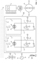
- FIG. 1 shows an exemplary embodiment of a gas measuring device 100 according to the invention, which is capable of monitoring a spatial area B for the presence of at least one combustible target gas.
- a detector 10 is arranged in a detector chamber 8.
- a compensator 11, described further below, is arranged in a compensator chamber 5.
- the two chambers 8, 5 are arranged in a housing 4.
- the detector chamber 8 and thus the detector 10 are in fluid communication with the area B to be monitored via an opening ⁇ 1.
- the compensator chamber 5 and thus the compensator 11 are in fluid communication with the area B via an opening ⁇ 2. Thanks to the openings ⁇ 1, ⁇ 2, a gas sample Gp from the area B can reach the interior of the housing 4 and from there to the two chambers 8, 5.
- An optional flame protection 2 for example a metallic grid, in front of the openings ⁇ 1, ⁇ 2 reduces the risk of flames escaping from a chamber 8, 5.
- a thermal barrier (not shown) inside the gas measuring device 100 thermally separates the detector 10 from the compensator 11.
- the electrical voltage U10 applied to detector 10 causes an electrical current I to flow.
- the flowing current I heats the heating detector segment 20 to a working temperature, which is often between 400 °C and 500 °C.
- this working temperature alone is generally not sufficient to oxidize a combustible target gas in detector chamber 8.
- a higher working temperature is often undesirable because it could lead to uncontrolled combustion or decomposition or even explosion of the combustible target gas, which is often undesirable, and also consumes more electrical energy.
- the detector 10 comprises a catalytic material which, in conjunction with the heated heating detector segment 20, oxidizes the target gas oxidized. Therefore, a gas measuring device with such a detector 10 is also referred to as a "catalytic sensor.”
- the heating detector segment 20 is surrounded by electrical insulation, for example, a ceramic sheath.
- This electrical insulation electrically insulates the heating detector segment 20 and, in particular, prevents unwanted short circuits.
- the electrical insulation is thermally conductive so that the heating detector segment 20 can dissipate thermal energy into the environment of the detector 10, and conversely, thermal energy inside the detector chamber 8 can further heat the heating detector segment 20.
- a coating of a catalytic material is applied to this electrical insulation. Or a catalytic material is embedded in the electrical insulation. This catalytic coating comes into contact with the gas mixture in the detector chamber 8 and thus also with a combustible target gas.
- a detector 10 constructed in this way is often referred to as a "pellistor.”
- catalytic material 26 platinum, palladium, or rhodium, or an alloy containing at least one of these materials, is used as the catalytic material.
- catalytic material 26 can also be embedded in the ceramic casing 25.
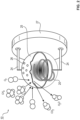
- the solid sphere of the detector 10 has a porous surface with a catalytic coating 26.
- this porous surface is manufactured as follows: The detector 10 with the porous surface but without the catalytic coating is provided. The catalytic coating 26 is applied to the porous surface, and a portion of the catalytic material penetrates into the interior of the detector 10. Thanks to this porous surface, the detector 10 has a larger surface area compared to a smooth surface. Thanks to this larger surface area, the detector 10 is better able to oxidize combustible target gas, in particular because a larger amount of target gas comes into contact with the catalytic material. Thanks to the porous surface, a gas can penetrate into deeper layers of the detector 10.
- the compensator 11 is constructed in the same way as the detector 10 and also includes a heating segment, designated by reference numeral 38. However, in one embodiment, a smaller amount of gas can reach the compensator 11 per unit of time than the detector 10. In another embodiment, the compensator 11 does not include a catalytic coating 26 or includes a catalytic coating 26 that is capable of oxidizing less target gas per unit of time than the detector 10.
- the protective layer 35 covers at least the conductor track 30, preferably the entire carrier plate 31, and prevents the conductor track 30 from coming into direct contact with a gas mixture.
- the protective layer 35 is made of silicon nitride.
- a catalytically active material is applied to the protective layer 35, at least in a region above the heating segment 32.
- the compensator 11 can in turn be constructed in the same way as the detector 10 of Figure 3 or and Figure 4 or have less or even no catalytically active material.
- the temperature of the detector 10 and thus also the or each detection variable is influenced not only by the released heat energy, but also by the ambient conditions in the area B to be monitored.
- the three essential ambient conditions are the ambient temperature Temp, the ambient pressure P and the ambient humidity Hum.
- both the zero point of the detector 10 and the increase in the detector temperature depend not only on the target gas concentration, but also on the ambient temperature Temp.
- the zero point is the value that the detector detection variable assumes when no target gas is present.
- These three ambient conditions Temp, P, Hum can also change the conditions inside the housing 4 and thus also in the detector chamber 8.
- These ambient conditions can namely also influence the detector temperature and thus a detection variable U10, for example because the thermal conductivity in the environment of the detector 10 is changed.
- the gas measuring device 100 is, on the one hand, capable of reliably detecting a combustible target gas despite varying ambient conditions and, on the other hand, generates only a few false alarms, i.e., only rarely decides that a target gas is present even though in reality no target gas has occurred above a detection limit, which is an erroneous result.
- the three environmental conditions temperature, pressure, humidity are designated Temp, P, Hum, values of these three environmental conditions are designated temp, p, hum.
- the gas measuring device 100 is capable of computationally compensating, to a certain extent, the influence of the three ambient conditions Temp, P, Hum on the detection variable.
- the current intensity 1.1 is kept constant by closed-loop control, and the electrical voltage U10 applied to the detector 10 acts as the detection variable.
- this detection variable U10 depends on the temperature of the heating detector segment 20. This temperature, in turn, depends on the target gas concentration on the one hand and on the three ambient conditions just mentioned on the other.
- the gas measuring device 100 comprises, in addition to the detector 10, the already mentioned compensator 11 in the compensator chamber 5, cf.
- the compensator 11 also includes a wire with a heating compensator segment 38.
- An electrical voltage U11 is also applied to the compensator 11, causing an electrical current I2 to flow and heating the heating segment 38 of the compensator 11.
- the compensator 11 is also exposed to varying environmental conditions.
- the compensator 11 also includes a spirally wound and electrically conductive wire, which functions as a heating compensator segment and is designated by reference numeral 38.
- the compensator 11 also includes a ceramic casing, a mounting plate, electrical connections, and mechanical supports. In one embodiment, however, the ceramic casing of the compensator 11, unlike the detector 10, is not provided with a catalytic coating.
- the compensator 11 is constructed in the same way as the detector 10, thus also comprising a ceramic coating. This ceramic coating is also catalytically active in the other embodiment.
- the gas measuring device 100 is designed such that less gas can reach the compensator 11 from the region B to be monitored than the detector 10 in a unit of time.
- the heating segment 38 of the compensator 11 is heated to a lower temperature than the heating segment 20 of the detector 10.
- Figure 1 shows the compensator 11 in the compensator chamber 5. It can be seen that the detector 10 comprises the heating detector segment 20 and the compensator 11 comprises the heating compensator segment 38.
- the compensator 11 is also designed as a spherical pellistor, but unlike the detector 10, it does not comprise a catalytically active coating 26.
- the detector 10 is supplied with electrical energy by a voltage source 43, and the compensator 11 by a voltage source 44.
- a detector circuit 3.1 comprises the detector 10 and the voltage source 43
- a compensator circuit 3.2 comprises the compensator 11 and the voltage source 44. Because two independent circuits 3.1 and 3.2 are implemented, the electrical voltage U11 applied to the compensator 11 can differ from the electrical voltage U10 applied to the detector 10, and the strength of the current flowing in the compensator circuit 3.2 can deviate from the strength of the current flowing in the detector circuit 3.1.
- the two voltage sources 43, 44 are preferably implemented with rechargeable batteries (accumulators). It is possible that the same voltage supply unit functions as both the first voltage source 43 and the second voltage source 44.
- a voltage sensor 12.1 measures the electrical voltage U10 applied to detector 10.
- a current sensor 13.1 measures the strength I.1 of the electrical current flowing through circuit 3.1 for detector 10.
- a voltage sensor 12.2 measures the electrical voltage U11 applied to compensator 11.
- a current sensor 13.2 measures the strength I.2 of the electrical current flowing through circuit 3.2 for compensator 11.
- a combustible target gas only affects the detector 10, while the ambient conditions are similar for the detector 10 and the compensator 11. If these ideal conditions are met, the difference between the detector detection value U10 and the compensator detection value U11 - optionally corrected by a zero value - a reliable measure of the desired concentration of the target gas under any possible combination of ambient conditions.
- the gas measuring device 100 measures the ambient temperature, preferably at a measuring position on an outer surface of the gas measuring device 100.
- the invention can also be implemented without the gas measuring device 100 comprising a temperature sensor.
- a temperature sensor 14 of the gas measuring device 100 is capable of measuring the ambient temperature Temp.
- the temperature sensor 14 provides the temperature difference ⁇ Temp between the current ambient temperature and a predetermined reference ambient temperature of, for example, 20°C.
- the temperature sensor 14 provides an analog or digital signal that includes information about the ambient temperature Temp—in the exemplary embodiment, the temperature difference ⁇ Temp.
- the influence of the ambient temperature Temp on the detection variable is computationally compensated to a certain extent with the help of a signal from the temperature sensor 14.
- the gas measuring device 100 from Figure 1 it comprises a sensor 17 for the ambient pressure P and a sensor 18 for the ambient humidity Hum.
- the sensors 17, 18 can be constructed relatively simply, so that the ambient humidity Hum and/or the ambient pressure P can only be measured with a relatively large measurement error.
- each sensor 17, 18 can be activated and deactivated. For example, a user switches off a sensor 17 or 18 if the gas measuring device 100 is or is to be used in an environment in which the activated sensor 17 or 18 can be damaged, for example due to very high pressure or very high humidity or a specific gas in the environment. It is also possible that a sensor 17, 18 is defective and the gas measuring device 100 is to be used nevertheless.
- the gas measuring device 100 comprises a reliable sensor 14 for the ambient temperature Temp, but only a relatively simple and/or deactivatable sensor 18 for the ambient pressure P, or none at all, and a relatively simple and/or deactivatable sensor 17 for the ambient humidity Hum.
- a temperature sensor 14 can be chemically insulated from the environment, specifically by insulating material with good thermal conductivity. The temperature sensor 14 is capable of measuring the ambient temperature Temp relatively reliably, but is not directly exposed to the other ambient conditions.
- Both a pressure sensor and a humidity sensor must generally be in fluid communication with the environment, i.e., with the spatial area B to be monitored, and can therefore be exposed to flammable target gases and other potentially harmful substances over a very long period of time.
- a sensor that is in fluid communication with the environment and yet sufficiently robust and reliable is often relatively expensive and/or heavy and/or requires a relatively high electrical power consumption.
- a temperature sensor does not have this disadvantage or at least only to a lesser extent.
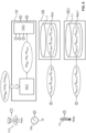
- a schematically shown signal-processing control unit 6 with an evaluation unit 9 receives signals from the sensors 12.1, 12.2, 13.1, 13.2, 14, 17, 18 and determines the current concentration of a combustible target gas in the monitored area B, thus deriving an estimated value.
- This estimated value generally varies over time. If several combustible target gases are present in area B, in the exemplary embodiment the estimated value describes the summed concentrations of these combustible target gases.
- the control unit 6 and thus the evaluation unit 9 have at least temporary read access to a data memory 7 in which an evaluation program and/or a computer-evaluable model Mod with several functional relationships are stored.
- the gas measuring device 100 would fully compensate for the influence of all three environmental conditions—i.e., the influence of the ambient temperature Temp, the influence of the ambient pressure P, and the influence of the ambient humidity Hum—with the aid of the compensator 11 and the temperature sensor 14 alone, for every possible value of these three environmental conditions during use.
- this is generally not possible in practice, at least not if the ambient pressure P and/or the ambient humidity Hum can vary considerably during use and neither a pressure sensor nor a humidity sensor is present and activated.
- a key reason for this is that in many cases the compensator 11 and the detector 10 react differently to at least one environmental condition, particularly due to design-related or construction-related differences or unavoidable manufacturing tolerances.
- a value range is specified for each of the three ambient conditions: temperature Temp, humidity Hum and pressure P.
- the value range for temperature extends from Temp min to Temp max , the value range for humidity from Hum min to Hum max and the value range for pressure from P min to P max .
- the gas measuring device 100 achieves the following described effect if each of these three environmental conditions is within the specified value range.
- the gas measuring device 100 of the exemplary embodiment can be selectively operated in one of four different possible modes. In one embodiment, one of these four modes is selected during configuration of the gas measuring device 100 and implemented using appropriate software. The model Mod in the data memory 7 is then valid for this selected mode. The gas measuring device 100 cannot necessarily be switched from one mode to another during operation.
- the gas measuring device 100 comprises a schematically shown switch 16 with which a user can select one of these four possible modes. The user actuates the switch 16 to switch from one mode to another.
- This switch 16 can be implemented, for example, as a mechanical switch or with the aid of a touchscreen or multiple buttons.
- a model for each mode is stored in the data memory 7.
- the gas measuring device 100 automatically switches from one mode to the other during operation, so that it is operated in each of the possible modes during use. In each mode, the gas measuring device 100 determines an estimated value for the target gas concentration. As a rule, the estimated values differ from mode to mode.
- a preferred embodiment for deriving an estimated value and preferably displaying it to a user is as follows: As long as an estimated value determined in a mode lies within a predetermined target concentration range, this estimated value is output. Or no message is output at all, or a message is output stating that there is no impermissible target gas concentration. If, however, at least one estimated value lies outside the predetermined target concentration range, the estimated value that is furthest from the predetermined target concentration range is output, i.e. the largest estimated value of a dangerous target gas or the smallest estimated value of a vital Target gas, e.g., oxygen. With this design, you're on the safe side.
- P The influence of the ambient pressure P is compensated as best as possible (pressure-optimized mode).
- Hum The influence of the ambient humidity Hum is compensated as best as possible (humidity-optimized mode).
- P_Hum The influence of the ambient pressure P is compensated as well as possible while maintaining a boundary condition concerning the ambient humidity Hum (pressure compensating mode).
- Hum_P the influence of the ambient humidity is compensated as well as possible while maintaining a boundary condition concerning the ambient pressure P (humidity compensating mode).
- the boundary condition relating to the ambient humidity Hum is predefined and specifies, for example, that the measured value con for the target gas concentration Con varies by a maximum of x% if the ambient humidity Hum remains within the predefined humidity range from Hum min to Hum max and the actual target gas concentration con remains constant. During use, the ambient humidity Hum always lies within this humidity range. The same applies to the boundary condition relating to the ambient pressure P, i.e., the ambient pressure lies within the range from P min to P max .
- the gas measuring device 100 can therefore be operated in one of four possible modes. This allows the gas measuring device 100 to be adapted to different operating conditions.
- a possible application condition is the following:
- the target gas concentration is to be measured in a pipe with a gas mixture flowing through it.
- the ambient pressure P can fluctuate significantly, which is why the P mode or the P_Hum mode are appropriate.
- the target gas concentration in an enclosed space is to be measured.
- This enclosed space is only fluidically connected to the environment via a relatively small opening and is, for example, a container for fluids.
- the enclosed space is a test chamber in which different ambient conditions, and in particular different humidities, are created to test a component.
- the ambient humidity Hum can fluctuate significantly, which is why the Hum or Hum_P modes are useful.
- the invention makes it possible to produce a set of identical gas measuring devices and to adapt each gas measuring device 100 of this set to the respective operating condition by selecting one of four possible modes. The selection is made in advance or during operation. Operation in a specific mode requires the implementation or selection of software, while the hardware remains unchanged. This configuration increases reliability in many cases and reduces design and construction costs compared to a configuration in which at least two sets of different gas measuring devices are produced, one set for each operating condition.
- the electrical detector voltage U10 applied to the detector 10 acts as the detection variable, which correlates with the temperature of the heating segment 20 of the detector 10, cf.
- the current I.1 is kept constant.
- the electrical compensator voltage U11 applied to the compensator 11 acts as the detection variable, which correlates with the temperature of the heating segment 38 of the compensator 11.
- the current I.2 is kept constant.
- the three sensors 14, 17, and 18 also each provide an electrical signal—of course, only if they are actually present, intact, and activated. This signal is designated U( ⁇ Temp), U(Hum), and U( ⁇ P), respectively.
- This signal is designated U( ⁇ Temp), U(Hum), and U( ⁇ P), respectively.
- the three environmental conditions ambient temperature, ambient humidity, Hum and ambient pressure P each have a linear effect on the detection variables. Therefore, a proportionality factor is determined in advance for each of these three environmental conditions, preferably empirically, and used during operation.
- the evaluation unit 9 calculates a value for a total detection quantity Det depending on the values for the five variables U10, U11, U( ⁇ Temp), U(Hum), U( ⁇ P).
- the function F depends on at least one parameter for U10 and U11, optionally on at least one further parameter.
- the amplification factor ⁇ compensates to a certain extent for design-related differences between the detector 10 and the compensator 11 and is preferably greater than 1.1.
- the amplification factor ⁇ compensates to a certain extent for the assumed linear influence of the ambient temperature Temp on the overall detection variable Det. Accordingly, the factors ⁇ and ⁇ compensate for the also assumed linear influence of the ambient humidity Hum and the ambient pressure ⁇ P.
- the parameters of the function F in equations (1) to (3) are calculated empirically using a sample. It is also possible that the function F takes the form of a neural network or is generated by another learning method.
- Con meas ⁇ Con * Det with an empirically determined factor ⁇ Con .
- Con denotes the actual target gas concentration, and Con meas the measured value.
- Con meas Con.
- the calculation rule (4) or (5) is set such that a value of zero for the total detection quantity Det leads to a value of zero for the target gas concentration Con.
- Both the function F and the function Fcon are stored in the data memory 7 in a suitable computer-evaluable manner and form part of the model Mod.
- the evaluation unit 9 uses a function F P , F P_Hum , F Hum or F Hum_P as function F in the calculation rule (1). If the calculation rule (2) or (3) is used, then, depending on the mode, a gain factor ⁇ P , ⁇ P_Hum , ⁇ Hum or ⁇ Hum_P is used as the gain factor ⁇ for the compensator voltage U11. Accordingly, a gain factor ⁇ P , ⁇ P_Hum , ⁇ Hum or ⁇ Hum_P is used as the gain factor ⁇ for the signal U( ⁇ Temp) of the temperature sensor 14. In one embodiment, four different zero values are used accordingly, in another embodiment the same zero value x0 is always used regardless of the mode.
- Figure 5 to Figure 7 illustrate given boundary conditions for how the measured value Con meas for the target gas concentration Con depends on the temperature difference ⁇ Temp ( Figure 5 ), from the ambient pressure P ( Figure 6 ) or the ambient humidity Hum ( Figure 7 ).
- On the x-axis is the deviation ⁇ Temp of the ambient temperature Temp from a reference ambient temperature in [degrees C] ( Figure 5 ), the deviation ⁇ P of the ambient pressure P from a given reference pressure in [mbar] ( Figure 6 ) or the ambient humidity Hum in [% rel. humidity] ( Figure 7 ).
- the deviation between the measured value con meas and the actual target gas concentration con in [% LEL] is plotted on the ⁇ -axis. Shown are a tolerance band Tol Temp for the dependence on the ambient temperature Temp, a tolerance band Tol P for the dependence on the ambient pressure P, and a tolerance band Tol Hum for the dependence on the ambient humidity Hum.
- the same function Fcon is determined for each mode in the calculation rule (4), for which the sample is used.
- the functions F P , F P_Hum , F Hum , or F Hum_P are further determined in the calculation rule (1).
- the values for the ambient temperature Temp in the sample cover the entire value range from Temp min to Temp max .
- the values for the ambient pressure P in the sample cover the entire value range from P min to P max .
- the values for the ambient humidity Hum in the sample cover the entire value range from Hum min to Hum max .
- the values for the actual target gas concentration in the sample cover the entire value range in which the gas measuring device 100 can be used.
- a subsample with multiple sample elements is selected from the sample.
- This subsample includes different values for the target gas concentration.
- the function in calculation rule (4) is determined empirically, for example, the factor ⁇ Con in calculation rule (5).
- the functions F P , F P_Hum , F Hum and/or F Hum_P are determined.
- Calculation rule (4), which was determined using the partial sample, is retained. Each remaining sample element therefore provides a calculated value con meas for the target gas concentration Con.
- the following example describes how values for the parameters of calculation rule (2) are derived.
- This derivation assumes that the three ambient conditions Temp, P, Hum, and the actual target gas concentration Con independently affect the total detection variable Det and thus the measured target gas concentration Con meas .
- the ambient temperature Temp has an approximately linear effect on the total detection variable Det and thus on the measured target gas concentration Con meas , so that the influence of the ambient temperature Temp can be compensated with sufficient accuracy using the factor ⁇ . In many cases, these assumptions correspond sufficiently closely to reality.
- the gas measuring device 100 is exposed to a defined reference test environment Cond Ref .
- the reference test environment Cond Ref has a reference concentration con Ref of the target gas to be detected, a reference ambient temperature temp Ref , a reference ambient pressure p Ref , and a reference ambient humidity hum Ref .
- the factor ⁇ Ref is initially set to 0, i.e., the influence of the ambient temperature Temp and thus the signal U( ⁇ Temp) are initially neglected.
- the factor ⁇ Ref is initially set to 1, i.e., the total detection value Det depends on the difference between the two voltages U10 and U11.
- the factors ⁇ Ref and ⁇ Ref can assume other values.
- the zero value x0 is always set so that the total detection quantity Det and thus the measured target gas concentration Con meas for the reference test environment Cond Ref , i.e. in the absence of combustible target gas, assume the value 0.
- a value for the factor ⁇ Con is then empirically determined in the calculation rule (5).
- the reference test environment Cond Ref is modified such that it has successively different target gas concentrations con(1), ...
- the gas measuring device 100 provides a value det(1), ... for the total detection variable Det.
- the gas measuring device 100 uses the just determined or set factors ⁇ Ref , ⁇ Ref and x0. This procedure provides a sample ⁇ [con(1), det(1)], ... ⁇ .
- the factor ⁇ Con is determined using this sample with the aid of a regression analysis.
- FIG 8 and Figure 9 illustrate an example of a procedure in which the gas measuring device 100 is exposed to two different defined test environments Cond Hum and Cond P.
- a calibration device 110 with a first component 110.1 and a second component 110.2 as well as a further gas measuring device 100.1 are shown, wherein the gas measuring device 100.1 is identical in construction to the gas measuring device 100.
- the test environment Cond Hum has a significantly higher ambient humidity Hum than the reference test environment Cond Ref , while the other ambient conditions Con, Temp, P are the same.
- the relative ambient humidity Hum is 0% in the reference test environment Cond Ref and 90% in the test environment Cond Hum , which is the highest value at which the gas measuring device 100 can still be used.
- the test environment Cond P has a significantly higher or lower ambient pressure P than the reference test environment Cond Ref , while the other ambient conditions Con, Temp, Hum are the same.
- the test environment Cond P has an ambient pressure P that is 200 mbar higher than the reference test environment Cond Ref .
- the gas measuring device 100 supplies a value u10(Cond Hum ), u11(Cond Hum ), u( ⁇ Temp) (Cond Hum ) for the three signals U10, U11, U( ⁇ Temp) for the test environment Cond Hum , and a value u10(Cond P ), u11(Condp), u( ⁇ Temp) (Condp) for the test environment Condp.
- the values ⁇ ref and ⁇ Con which were determined or set as just described, are used.
- a value is determined for the gain factor ⁇ , which is described below.
- the zero value x0 is set such that a target gas concentration of zero is measured in the reference test environment Cond Ref , i.e. in the absence of combustible target gas.
- Figure 8 shows two measurement curves 50 P , 50 Hum , which were generated with the same gas measuring device 100.
- the amplification factor ⁇ is plotted on the x-axis, and the resulting deviation of the measurement result con meas from the actual target gas concentration con in % LEL (Lower Explosion Level) is plotted on the ⁇ -axis, whereby this deviation con meas - con depends on the amplification factor ⁇ .
- Calculation rules (3) and (5) were used for this. Therefore, a positive or negative deviation of the measured target gas concentration Con meas from the actual target gas concentration Con can occur.
- the measurement curve 50 p was obtained in the test environment Cond P , the measurement curve 50 Hum in the test environment Cond Hum .
- the gas measuring device 100 delivers the correct value 0 for the target gas concentration Con.
- the value ⁇ which compensates for the influence of the ambient temperature Temp, is adjusted, for example, by exposing the gas measuring device 100 to a changed ambient temperature and checking the resulting measured value con meas .
- This procedure delivers a set of parameter values ⁇ Hum , ⁇ Hum , x0 Hum . This set of parameter values is used for the humidity-optimized mode Hum
- This value is used for the pressure-optimized mode P.
- a set of parameter values ⁇ P , ⁇ P , x0 P for the pressure-optimized mode P is derived.
- the boundary condition is used that the measured target gas concentration Con meas should deviate from the actual target gas concentration Con at any ambient humidity Hum by a maximum of 10% LEL.
- This boundary condition is defined in Figure 8 indicated by the tolerance band Tol Hum .
- a set of parameter values ⁇ P_Hum , ⁇ P_Hum , x0 P_Hum for the pressure-compensating mode P_Hum is derived.
- the target gas concentration Con affects the detection parameters U10, U11, U( ⁇ Temp) independently of the ambient conditions Temp, P, Hum. Therefore, the calculation rule (5) with the already determined factor ⁇ Con is preferred. It is also possible to empirically determine a factor ⁇ Con for each mode.
- Figure 9 illustrates, by way of example, how two gas measuring devices 100 and 100.1 are calibrated using a calibration device 110 before their first use.
- the two gas measuring devices 100 and 100.1 are identical in construction and, in particular, have the same detectors and compensators. They are, for example, as described with reference to Figure 1 described, but do not necessarily include a switch 16.
- the gas measuring device 100 is intended to be operated in the pressure-compensating mode P_Hum, the gas measuring device 100.1 in the humidity-compensating mode Hum_P.
- the calibration device 110 provides a set ⁇ P_Hum , ⁇ P_Hum , x0 P_Hum of parameter values for the pressure-compensating mode P_Hum and a set ⁇ Hum_P , ⁇ Hum_P , x0 Hum_P of parameter values for the humidity-compensating mode Hum_P.
- the gas measuring device 100 is used with the temperature sensor 14.
- a humidity sensor 117 and a pressure sensor 118 are used to create the respective test environment Cond Ref , Cond P , Cond Hum .
- the two sensors 117 and 118 are robust and reliable and are used only for calibration and are not components of the gas measuring devices 100, 100.1.
- the procedure just described uses the calculation rules (3) and (5), and three different test environments, Cond Ref , Cond P , and Cond Hum , are used. In many cases, this procedure results in a gas measuring device 100, 100.1 that is capable of measuring the target gas concentration Con with sufficient accuracy in the respective mode. A more generally applicable procedure is described below. This procedure requires more effort and computation time.
- mode P i.e. the mode in which the influence of the ambient pressure P is compensated as best as possible.
- switch 16 In the position shown, switch 16 is in this mode P.
- a first sample of measured values is determined.
- No combustible target gas is present, i.e. the target gas concentration is zero.
- the ambient humidity Hum assumes a constant value hum 0 , for example 0%.
- the ambient pressure P assumes M different values p(1), ..., p(M) from the value range from P min to P max , the ambient temperature N different values temp(1), ..., temp(N) from the value range from Temp min to Temp max .
- N ⁇ M. It is possible that N equals 1, i.e. that the ambient temperature Temp is the same for all values of the first sample of measured values.
- the M values p(1), ..., p(M) for the ambient pressure P and the N values temp(1), ..., temp(N) for the ambient temperature Temp are chosen so that they can actually occur during use.
- the gas measuring device 100 is successively exposed to these M*N different conditions x 1,1 , ..., x M,N , and the three detection variables U10, U11, U( ⁇ Temp) are measured.
- Each condition x i,j leads to three measured values u10(x i,j ), u11(x i,j ), u( ⁇ Temp)(x i,j ) for the three variables U10, U11, U( ⁇ Temp).
- the first sample of measured values consists of M*N sample elements, where each sample element has the form u 10 x i , j , u 11 x i , j , u ⁇ Temp x i , j ; p i , ⁇ temp j , hum 1 has.
- the total detection variable Det is set so that it depends as little as possible, ideally not at all, on the ambient pressure P. It is accepted that it depends relatively strongly on the ambient humidity Hum and at least somewhat on the ambient temperature Temp.
- x values par(1), ..., par(x) must be defined for the x parameters Par(1), ..., Par(x) of the function FP .
- the parameter values par(1), ..., par(x) are defined such that they result in a minimal empirical variance Var in the first detection quantity sample.
- an objective function is numerically minimized.
- the variables of these objective functions are the x parameters Par(1), ..., Par(x) of the function FP .
- F P,10,11 and F P,Temp each depend on at least one parameter.
- a value is determined for the or each parameter of the function F P,10,11 .
- a value is determined for the parameters ⁇ P and x0 P.
- a reduced first detection quantity sample is used, in which the measured values of the temperature sensor 14 are omitted.
- Each sample element of this reduced detection quantity sample therefore has the form det x i ,j ; u10 x i ,j , u11 x i ,j
- the respective value for the or each parameter of the function F P,10,11 is set such that the measure of empirical variance Var is minimized.
- the function F P,10,11 is defined.
- This function F P,10,11 is applied to the reduced detection size sample. More precisely:
- the function F P,10,11 is applied to the respective two values u10(x i,j ), u11(x i,j ) in each sample element of the form (8), namely det x i ,j ; u10 x i ,j , u11 x i ,j , u ⁇ Temp x i ,j applied.
- det P,10,11 (x i,j ) F P,10,11 [u10(x i,j ), u11(x i,j )] a reduced second detection size sample is generated in which each sample element has the form det x i ,j ; det P ,10 ,11 x i ,j , u ⁇ Temp x i ,j Using this sample, a value is determined for the or each parameter of the function F P,Temp . In the case of calculation rule (3), this is a value for the single parameter ⁇ P . The or each value is again determined in such a way that the measure of variance Var is minimized.
- the zero value x0 P is determined under typical ambient conditions and depending on a gain factor ⁇ .
- the ambient conditions are, for example, 20 °C, 1000 mbar, and 0% relative humidity.
- the two detection quantity samples just described are used to first calculate the gain factor ⁇ P for the compensator voltage U11 and then the gain factor ⁇ P for the measured ambient temperature U( ⁇ Temp).
- the previously used zero value x0 is used without changing it.
- a second sample of measured values is determined in addition to the first.
- the ambient humidity Hum assumes the constant value hum 0
- the ambient pressure PM takes on various values
- the ambient temperature Temp N takes on various values.
- flammable target gas is present in the environment.
- the function derived empirically using the first sample of measured values is denoted by F P,0 .
- a function F P,con is derived empirically.
- the applied function F is derived by suitable averaging of the two functions F P,0 and F P,con .
- the measured value con meas for the target gas concentration Con meas should vary by a maximum of x% depending on the ambient humidity Hum, provided the ambient humidity Hum remains within a specified humidity range.
- the first sample of measurements is used, i.e. a sample with sample elements, where each sample element has the form (6), i.e. u10 x i , u11 x i , u ⁇ Temp x i ; ⁇ temp i , p i , hum 1
- the first sample of measured values shows the same ambient humidity hum(x 1 ) throughout.
- a value hum(2), ..., hum(K) is set for the ambient humidity Hum, whereby the total K values hum(1), ..., hum(K) are all different from one another.
- the above-mentioned boundary condition that the measured value con for the target gas concentration Con should vary by a maximum of x% depending on the ambient humidity Hum leads to a boundary condition for the total detection variable Det.
- the factor y depends on the specified functional relationship between the target gas concentration Con and the total detection variable Det, whereby this relationship is described by the calculation rule (4), in particular by the calculation rule (5).
- the total detection variable Det should lie within a tolerance band of width y% with fluctuating ambient humidity Hum.
- the parameter values par(1), ..., par(x) for the function F P_Hum of the calculation rule (18) are set such that the boundary condition (21) is met.
- Gas measuring device comprises the detector 10, the compensator 11, the temperature sensor 14, the control unit 6 and the data memory 7 as well as optionally the humidity sensor 17 and the pressure sensor 18 2 optional flame protection in front of the openings ⁇ 1, ⁇ 2 5 Compensator chamber, surrounds the compensator 11 6
- Control unit receives signals from sensors 12.1, 12.2, 13.1, 13.2, 14 7 Data storage in which the model mod is stored 7.1
- Detector chamber surrounding the detector 10 9 Evaluation unit, belonging to control unit 6, derives the target gas concentration Con meas 10 Detector, includes the heating segment 20 11 Compensator, includes the heating segment 38 12.1 Voltage sensor, measures the voltage U10 12.2 Voltage sensor, measures the voltage U11 13.1 Current sensor, measures the current 1.1 13.2 Current sensor, measures the current 1.2 14 Temperature sensor, measures the difference ⁇ Temp between the ambient temperature and a reference temperature 16 Selection unit in the form of a switch with which a user can select a mode 17 Hu
Landscapes
- Chemical & Material Sciences (AREA)
- Engineering & Computer Science (AREA)
- Health & Medical Sciences (AREA)
- Life Sciences & Earth Sciences (AREA)
- Combustion & Propulsion (AREA)
- Analytical Chemistry (AREA)
- Physics & Mathematics (AREA)
- Biochemistry (AREA)
- General Health & Medical Sciences (AREA)
- General Physics & Mathematics (AREA)
- Immunology (AREA)
- Pathology (AREA)
- Medicinal Chemistry (AREA)
- Food Science & Technology (AREA)
- Chemical Kinetics & Catalysis (AREA)
- Electrochemistry (AREA)
- Investigating Or Analyzing Materials By The Use Of Electric Means (AREA)
Applications Claiming Priority (1)
| Application Number | Priority Date | Filing Date | Title |
|---|---|---|---|
| DE102023132371.7A DE102023132371A1 (de) | 2023-11-23 | 2023-11-21 | Gasmessvorrichtung und Gasmessverfahren für ein Zielgas mit verbesserter Kompensation einer Umgebungsbedingung |
Publications (1)
| Publication Number | Publication Date |
|---|---|
| EP4560302A1 true EP4560302A1 (fr) | 2025-05-28 |
Family
ID=93463024
Family Applications (1)
| Application Number | Title | Priority Date | Filing Date |
|---|---|---|---|
| EP24212102.8A Pending EP4560302A1 (fr) | 2023-11-23 | 2024-11-11 | Dispositif de mesure de gaz et procédé de mesure de gaz pour un gaz cible avec compensation améliorée d'une condition environnementale |
Country Status (3)
| Country | Link |
|---|---|
| US (1) | US12584874B2 (fr) |
| EP (1) | EP4560302A1 (fr) |
| DE (1) | DE102023132371A1 (fr) |
Families Citing this family (2)
| Publication number | Priority date | Publication date | Assignee | Title |
|---|---|---|---|---|
| CN120629281B (zh) * | 2025-07-17 | 2026-02-06 | 深圳市墨达科技有限公司 | 一种基于热导系数原理的多参数补偿式可燃气体探测方法及系统 |
| CN120820512A (zh) * | 2025-09-05 | 2025-10-21 | 山东省科学院自动化研究所 | 基于非色散红外的宽量程环氧乙烷气体传感器及测量方法 |
Citations (3)
| Publication number | Priority date | Publication date | Assignee | Title |
|---|---|---|---|---|
| US20180052124A1 (en) * | 2016-08-18 | 2018-02-22 | Nevada Nanotech Systems Inc. | Systems and methods for determining at least one property of a material |
| US20180335412A1 (en) * | 2017-05-17 | 2018-11-22 | Msa Technology, Llc | Comparative diagnostics for catalytic structures and combustible gas sensors including catalytic structures |
| DE102022102969A1 (de) * | 2021-02-22 | 2022-08-25 | Dräger Safety AG & Co. KGaA | Gasdetektionsvorrichtung mit einem Detektor und einem Kompensator und Gasdetektionsverfahren mit einer solchen Gasdetektionsvorrichtung |
Family Cites Families (10)
| Publication number | Priority date | Publication date | Assignee | Title |
|---|---|---|---|---|
| DE4130099C2 (de) * | 1991-09-11 | 1996-07-18 | Auergesellschaft Gmbh | Verfahren und eine Vorrichtung zum Feststellen des Vorliegens eines durch eine Meßkammer eines Gasmeßgerätes geförderten Meßgasstromes |
| DE102006059566B4 (de) * | 2006-12-16 | 2008-12-11 | Woelke Industrieelektronik Gmbh | Verfahren zum Betrieb eines Gasmessgerätes sowie zugehöriges Gasmessgerät |
| US8721970B2 (en) * | 2008-01-25 | 2014-05-13 | Life Safety Distribution Ag | Temperature and humidity compensated single element pellistor |
| JP6427226B2 (ja) * | 2017-05-30 | 2018-11-21 | 新コスモス電機株式会社 | 接触燃焼式ガスセンサ |
| DE102017005713A1 (de) * | 2017-06-19 | 2018-12-20 | Dräger Safety AG & Co. KGaA | Katalytischer Gassensor für brennbare Gase |
| US11029294B2 (en) * | 2019-04-05 | 2021-06-08 | Honeywell International Inc. | Method and apparatus for measuring humidity using an electrochemical gas sensor |
| CA3153895A1 (fr) * | 2019-10-22 | 2021-04-29 | Benjamin S. Rogers | Procedes de fonctionnement et d'etalonnage d'un capteur de gaz, et capteurs de gaz associes |
| US11703473B2 (en) * | 2019-12-11 | 2023-07-18 | Msa Technology, Llc | Operation of combustible gas sensor in a dynamic mode with a constant resistance setpoint |
| DE102022106689A1 (de) * | 2021-03-30 | 2022-10-06 | Dräger Safety AG & Co. KGaA | Gasdetektionsvorrichtung mit einem Detektor und einem Kompensator und Gasdetektionsverfahren |
| KR102641537B1 (ko) * | 2021-12-06 | 2024-02-27 | 주식회사 현대케피코 | 열전도식 가스감지센서 및 이를 이용한 가스 측정방법 |
-
2023
- 2023-11-21 DE DE102023132371.7A patent/DE102023132371A1/de active Pending
-
2024
- 2024-11-11 EP EP24212102.8A patent/EP4560302A1/fr active Pending
- 2024-11-20 US US18/953,386 patent/US12584874B2/en active Active
Patent Citations (3)
| Publication number | Priority date | Publication date | Assignee | Title |
|---|---|---|---|---|
| US20180052124A1 (en) * | 2016-08-18 | 2018-02-22 | Nevada Nanotech Systems Inc. | Systems and methods for determining at least one property of a material |
| US20180335412A1 (en) * | 2017-05-17 | 2018-11-22 | Msa Technology, Llc | Comparative diagnostics for catalytic structures and combustible gas sensors including catalytic structures |
| DE102022102969A1 (de) * | 2021-02-22 | 2022-08-25 | Dräger Safety AG & Co. KGaA | Gasdetektionsvorrichtung mit einem Detektor und einem Kompensator und Gasdetektionsverfahren mit einer solchen Gasdetektionsvorrichtung |
Also Published As
| Publication number | Publication date |
|---|---|
| DE102023132371A1 (de) | 2025-05-22 |
| US12584874B2 (en) | 2026-03-24 |
| US20250164425A1 (en) | 2025-05-22 |
Similar Documents
| Publication | Publication Date | Title |
|---|---|---|
| EP4560302A1 (fr) | Dispositif de mesure de gaz et procédé de mesure de gaz pour un gaz cible avec compensation améliorée d'une condition environnementale | |
| EP1183520B1 (fr) | Dispositif de capteur de gaz | |
| EP3285322B1 (fr) | Procédé de détermination de conditions de fonctionnement critiques d'une pile à combustible | |
| DE69821410T2 (de) | Gassensor | |
| DE102022106689A1 (de) | Gasdetektionsvorrichtung mit einem Detektor und einem Kompensator und Gasdetektionsverfahren | |
| DE69629640T2 (de) | NOx-Sensor und Messverfahren dazu | |
| DE69414258T2 (de) | Überwachung von mehrfachelektroden gassensoren | |
| DE102022102969A1 (de) | Gasdetektionsvorrichtung mit einem Detektor und einem Kompensator und Gasdetektionsverfahren mit einer solchen Gasdetektionsvorrichtung | |
| DE60027978T2 (de) | Gasanalysegerät und Kalibrierverfahren dafür | |
| EP2612137A1 (fr) | Procédé et dispositif pour détecter au moins une propriété d'un gaz | |
| EP4012405A1 (fr) | Appareil de mesure de gaz | |
| EP4043873B1 (fr) | Dispositif de détection de gaz et procédé de détection de gaz au moyen d'un détecteur et d'un modulateur | |
| EP4478040B1 (fr) | Dispositif et procédé de détection d'un gaz cible au moyen de plusieurs paires de capteurs-compensateurs | |
| WO2003036286A1 (fr) | Capteur utilise pour determiner une concentration en monoxyde de carbone d'un melange gazeux | |
| EP2083405A1 (fr) | Dispositif d'alerte d'incendie | |
| EP4266034B1 (fr) | Dispositif de détection de gaz et procédé de détection de gaz utilisant un composant de capteur et un composant d'oxydation | |
| EP4303577B1 (fr) | Ensemble capteur comprenant un capteur électrochimique et un capteur de température et procédé utilisant un tel ensemble capteur | |
| EP0421100B1 (fr) | Procédé et dispositif pour reconnaître des conditions dangereuses dans une pièce | |
| EP4273537B1 (fr) | Capteur électrochimique comprenant une cellule de mesure et un composant oxydant et procédé utilisant un tel capteur | |
| DE102023110687A1 (de) | Gasdetektionsvorrichtung und Gasdetektionsverfahren mit automatischer Störgrößen-Kompensation | |
| EP4321859B1 (fr) | Dispositif de mesure des gaz et méthode de mesure des gaz pour mesurer la concentration des gaz cibles et l'humidité ambiante | |
| DE102022109534A1 (de) | Gasdetektionsvorrichtung und Gasdetektionsverfahren mit einem Sensor-Bauteil und einem Oxidierungs-Bauteil | |
| DE102016215881A1 (de) | Verfahren zur Durchführung eines Erholungsprozesses von Gassensoren | |
| EP3964825A1 (fr) | Procédé de détermination d'au moins une propriété d'un fluide dans au moins une chambre de mesure | |
| DE102022116509A1 (de) | Gasdetektionsvorrichtung und Gasdetektionsverfahren mit einem Sensor-Bauteil und einem Oxidierungs-Bauteil |
Legal Events
| Date | Code | Title | Description |
|---|---|---|---|
| PUAI | Public reference made under article 153(3) epc to a published international application that has entered the european phase |
Free format text: ORIGINAL CODE: 0009012 |
|
| STAA | Information on the status of an ep patent application or granted ep patent |
Free format text: STATUS: THE APPLICATION HAS BEEN PUBLISHED |
|
| AK | Designated contracting states |
Kind code of ref document: A1 Designated state(s): AL AT BE BG CH CY CZ DE DK EE ES FI FR GB GR HR HU IE IS IT LI LT LU LV MC ME MK MT NL NO PL PT RO RS SE SI SK SM TR |
|
| STAA | Information on the status of an ep patent application or granted ep patent |
Free format text: STATUS: REQUEST FOR EXAMINATION WAS MADE |
|
| 17P | Request for examination filed |
Effective date: 20251128 |
|
| GRAP | Despatch of communication of intention to grant a patent |
Free format text: ORIGINAL CODE: EPIDOSNIGR1 |
|
| STAA | Information on the status of an ep patent application or granted ep patent |
Free format text: STATUS: GRANT OF PATENT IS INTENDED |
|
| GRAJ | Information related to disapproval of communication of intention to grant by the applicant or resumption of examination proceedings by the epo deleted |
Free format text: ORIGINAL CODE: EPIDOSDIGR1 |
|
| STAA | Information on the status of an ep patent application or granted ep patent |
Free format text: STATUS: REQUEST FOR EXAMINATION WAS MADE |
|
| GRAP | Despatch of communication of intention to grant a patent |
Free format text: ORIGINAL CODE: EPIDOSNIGR1 |
|
| STAA | Information on the status of an ep patent application or granted ep patent |
Free format text: STATUS: GRANT OF PATENT IS INTENDED |
|
| RIC1 | Information provided on ipc code assigned before grant |
Ipc: G01N 27/16 20060101AFI20260106BHEP Ipc: G01N 33/00 20060101ALI20260106BHEP |
|
| INTG | Intention to grant announced |
Effective date: 20260120 |
|
| INTC | Intention to grant announced (deleted) | ||
| INTG | Intention to grant announced |
Effective date: 20260205 |
|
| GRAS | Grant fee paid |
Free format text: ORIGINAL CODE: EPIDOSNIGR3 |
|
| GRAA | (expected) grant |
Free format text: ORIGINAL CODE: 0009210 |
|
| STAA | Information on the status of an ep patent application or granted ep patent |
Free format text: STATUS: THE PATENT HAS BEEN GRANTED |