EP4560330A2 - Dispositif de diagnostic de batterie et procédé de diagnostic de batterie - Google Patents
Dispositif de diagnostic de batterie et procédé de diagnostic de batterie Download PDFInfo
- Publication number
- EP4560330A2 EP4560330A2 EP23868472.4A EP23868472A EP4560330A2 EP 4560330 A2 EP4560330 A2 EP 4560330A2 EP 23868472 A EP23868472 A EP 23868472A EP 4560330 A2 EP4560330 A2 EP 4560330A2
- Authority
- EP
- European Patent Office
- Prior art keywords
- ocv
- soc
- battery
- data
- battery cell
- Prior art date
- Legal status (The legal status is an assumption and is not a legal conclusion. Google has not performed a legal analysis and makes no representation as to the accuracy of the status listed.)
- Pending
Links
Images


Classifications
-
- G—PHYSICS
- G01—MEASURING; TESTING
- G01R—MEASURING ELECTRIC VARIABLES; MEASURING MAGNETIC VARIABLES
- G01R31/00—Arrangements for testing electric properties; Arrangements for locating electric faults; Arrangements for electrical testing characterised by what is being tested not provided for elsewhere
- G01R31/36—Arrangements for testing, measuring or monitoring the electrical condition of accumulators or electric batteries, e.g. capacity or state of charge [SoC]
- G01R31/3644—Constructional arrangements
- G01R31/3648—Constructional arrangements comprising digital calculation means, e.g. for performing an algorithm
-
- G—PHYSICS
- G01—MEASURING; TESTING
- G01R—MEASURING ELECTRIC VARIABLES; MEASURING MAGNETIC VARIABLES
- G01R19/00—Arrangements for measuring currents or voltages or for indicating presence or sign thereof
- G01R19/003—Measuring mean values of current or voltage during a given time interval
-
- G—PHYSICS
- G01—MEASURING; TESTING
- G01R—MEASURING ELECTRIC VARIABLES; MEASURING MAGNETIC VARIABLES
- G01R19/00—Arrangements for measuring currents or voltages or for indicating presence or sign thereof
- G01R19/10—Measuring sum, difference or ratio
-
- G—PHYSICS
- G01—MEASURING; TESTING
- G01R—MEASURING ELECTRIC VARIABLES; MEASURING MAGNETIC VARIABLES
- G01R19/00—Arrangements for measuring currents or voltages or for indicating presence or sign thereof
- G01R19/165—Indicating that current or voltage is either above or below a predetermined value or within or outside a predetermined range of values
- G01R19/16533—Indicating that current or voltage is either above or below a predetermined value or within or outside a predetermined range of values characterised by the application
- G01R19/16538—Indicating that current or voltage is either above or below a predetermined value or within or outside a predetermined range of values characterised by the application in AC or DC supplies
- G01R19/16542—Indicating that current or voltage is either above or below a predetermined value or within or outside a predetermined range of values characterised by the application in AC or DC supplies for batteries
-
- G—PHYSICS
- G01—MEASURING; TESTING
- G01R—MEASURING ELECTRIC VARIABLES; MEASURING MAGNETIC VARIABLES
- G01R19/00—Arrangements for measuring currents or voltages or for indicating presence or sign thereof
- G01R19/165—Indicating that current or voltage is either above or below a predetermined value or within or outside a predetermined range of values
- G01R19/16566—Circuits and arrangements for comparing voltage or current with one or several thresholds and for indicating the result not covered by subgroups G01R19/16504, G01R19/16528, G01R19/16533
- G01R19/16576—Circuits and arrangements for comparing voltage or current with one or several thresholds and for indicating the result not covered by subgroups G01R19/16504, G01R19/16528, G01R19/16533 comparing DC or AC voltage with one threshold
-
- G—PHYSICS
- G01—MEASURING; TESTING
- G01R—MEASURING ELECTRIC VARIABLES; MEASURING MAGNETIC VARIABLES
- G01R31/00—Arrangements for testing electric properties; Arrangements for locating electric faults; Arrangements for electrical testing characterised by what is being tested not provided for elsewhere
- G01R31/36—Arrangements for testing, measuring or monitoring the electrical condition of accumulators or electric batteries, e.g. capacity or state of charge [SoC]
- G01R31/367—Software therefor, e.g. for battery testing using modelling or look-up tables
-
- G—PHYSICS
- G01—MEASURING; TESTING
- G01R—MEASURING ELECTRIC VARIABLES; MEASURING MAGNETIC VARIABLES
- G01R31/00—Arrangements for testing electric properties; Arrangements for locating electric faults; Arrangements for electrical testing characterised by what is being tested not provided for elsewhere
- G01R31/36—Arrangements for testing, measuring or monitoring the electrical condition of accumulators or electric batteries, e.g. capacity or state of charge [SoC]
- G01R31/382—Arrangements for monitoring battery or accumulator variables, e.g. SoC
- G01R31/3835—Arrangements for monitoring battery or accumulator variables, e.g. SoC involving only voltage measurements
-
- G—PHYSICS
- G01—MEASURING; TESTING
- G01R—MEASURING ELECTRIC VARIABLES; MEASURING MAGNETIC VARIABLES
- G01R31/00—Arrangements for testing electric properties; Arrangements for locating electric faults; Arrangements for electrical testing characterised by what is being tested not provided for elsewhere
- G01R31/36—Arrangements for testing, measuring or monitoring the electrical condition of accumulators or electric batteries, e.g. capacity or state of charge [SoC]
- G01R31/392—Determining battery ageing or deterioration, e.g. state of health
-
- G—PHYSICS
- G01—MEASURING; TESTING
- G01R—MEASURING ELECTRIC VARIABLES; MEASURING MAGNETIC VARIABLES
- G01R31/00—Arrangements for testing electric properties; Arrangements for locating electric faults; Arrangements for electrical testing characterised by what is being tested not provided for elsewhere
- G01R31/36—Arrangements for testing, measuring or monitoring the electrical condition of accumulators or electric batteries, e.g. capacity or state of charge [SoC]
- G01R31/396—Acquisition or processing of data for testing or for monitoring individual cells or groups of cells within a battery
-
- G—PHYSICS
- G01—MEASURING; TESTING
- G01R—MEASURING ELECTRIC VARIABLES; MEASURING MAGNETIC VARIABLES
- G01R31/00—Arrangements for testing electric properties; Arrangements for locating electric faults; Arrangements for electrical testing characterised by what is being tested not provided for elsewhere
- G01R31/50—Testing of electric apparatus, lines, cables or components for short-circuits, continuity, leakage current or incorrect line connections
- G01R31/52—Testing for short-circuits, leakage current or ground faults
-
- Y—GENERAL TAGGING OF NEW TECHNOLOGICAL DEVELOPMENTS; GENERAL TAGGING OF CROSS-SECTIONAL TECHNOLOGIES SPANNING OVER SEVERAL SECTIONS OF THE IPC; TECHNICAL SUBJECTS COVERED BY FORMER USPC CROSS-REFERENCE ART COLLECTIONS [XRACs] AND DIGESTS
- Y02—TECHNOLOGIES OR APPLICATIONS FOR MITIGATION OR ADAPTATION AGAINST CLIMATE CHANGE
- Y02E—REDUCTION OF GREENHOUSE GAS [GHG] EMISSIONS, RELATED TO ENERGY GENERATION, TRANSMISSION OR DISTRIBUTION
- Y02E60/00—Enabling technologies; Technologies with a potential or indirect contribution to GHG emissions mitigation
- Y02E60/10—Energy storage using batteries
Definitions
- Embodiments disclosed herein relate to a battery diagnosis apparatus and method.
- the secondary batteries which are chargeable/dischargeable batteries, may be interpreted as including all of conventional nickel (Ni)/cadmium (Cd) batteries, Ni/metal hydride (MH) batteries, etc., and recent lithium-ion batteries.
- lithium-ion batteries may have a higher energy density than conventional Ni/Cd batteries, Ni/MH batteries, etc., and may be manufactured to be small and lightweight, allowing them to have high usability in terms of power sources for mobile devices.
- the lithium ion battery is attracting attention as a next-generation energy storage medium as a usage range thereof is expanded to a power source of electric vehicles.
- Diagnosis of abnormal behavior may be performed based on a battery voltage to inspect the manufacturing quality of batteries or to diagnose whether a defect has occurred.
- abnormal behavior of the battery voltage may be diagnosed by using the deviation of cell voltages of battery cells, but this diagnosis method has a low diagnosis accuracy.
- Embodiments disclosed herein aim to provide a battery diagnosis apparatus and method by which abnormality of a voltage behavior may be diagnosed even when there is a little change in a battery voltage.
- a battery diagnosis apparatus includes a sensor configured to generate first open circuit voltage (OCV) data by measuring an OCV from a diagnosis target battery and a controller configured to obtain first SOC data regarding a state of charge (SOC) of the diagnosis target battery based on the first OCV data, derive second SOC data for estimating the SOC of the diagnosis target battery based on the first SOC data, obtain second OCV data of the diagnosis target battery based on the second SOC data, and diagnose a state of the diagnose target battery based on the first OCV data and the second OCV data.
- OCV open circuit voltage
- the diagnosis target battery may include a plurality of battery cells
- the first OCV data may include a plurality of OCV values measured at a plurality of time points for each of the plurality of battery cells.
- the controller may be further configured to calculate an average SOC value of a plurality of SOC values converted from the plurality of OCV values for each battery cell, calculate a relative capacity value of each battery cell based on the average SOC value, and calculate a plurality of estimated SOC values of each battery cell at the plurality of time points based on the relative capacity value.
- the controller may be further configured to calculate a pseudoinverse matrix of an average SOC matrix indicating the average SOC value of each battery cell and calculate a relative capacity matrix indicating the relative capacity value by multiplying the pseudoinverse matrix by an SOC matrix indicating the plurality of SOC values for each battery cell.
- the controller may be further configured to calculate an estimated SOC matrix indicating the plurality of estimated SOC values of each battery cell by multiplying the average SOC matrix by the relative capacity matrix.
- the controller may be further configured to derive OCV deviation data based on a difference between the first OCV data and the second OCV data and diagnose the state of the diagnose target battery based on the OCV deviation data.
- the OCV deviation data may include a plurality of OCV deviation values of each battery cell at the plurality of time points
- the controller may be further configured to calculate a plurality of OCV deviation change amounts indicating a difference between an OCV deviation value at a current time point and an OCV deviation value at a previous time point, based on the plurality of OCV deviation values of each battery cell and diagnose a state of each battery cell based on the plurality of OCV deviation change amounts of each battery cell.
- the controller may be further configured to diagnose that abnormality occurs in a first battery cell among the plurality of battery cells, when the plurality of OCV deviation change amounts of the first battery cell is greater than an upper limit of a normal range or is less than a lower limit of the normal range.
- the controller may be further configured to convert the first OCV data into the first SOC data based on an OCV-SOC mapping table and convert the second SOC data into the second OCV data based on the OCV-SOC mapping table.
- a battery diagnosis method includes generating first open circuit voltage (OCV) data by measuring an OCV from a diagnosis target battery, obtaining first SOC data regarding a state of charge (SOC) of the diagnosis target battery based on the first OCV data, deriving second SOC data for estimating the SOC of the diagnosis target battery based on the first SOC data, obtaining second OCV data of the diagnosis target battery based on the second SOC data, and diagnosing a state of the diagnose target battery based on the first OCV data and the second OCV data.
- OCV open circuit voltage
- the diagnosis target battery may include a plurality of battery cells
- the first OCV data may include a plurality of OCV values measured at a plurality of time points for each of the plurality of battery cells.
- the deriving of the second SOC data may include calculating an average SOC value of a plurality of SOC values converted from the plurality of OCV values for each battery cell, calculating a relative capacity value of each battery cell based on the average SOC value, and calculating a plurality of estimated SOC values of each battery cell at the plurality of time points based on the relative capacity value.
- the calculating of the relative capacity value may include calculating a pseudoinverse matrix of an average SOC matrix indicating the average SOC value of each battery cell and calculating a relative capacity matrix indicating the relative capacity value by multiplying the pseudoinverse matrix by an SOC matrix indicating the plurality of SOC values for each battery cell.
- the calculating of the plurality of estimated SOC values may include calculating an estimated SOC matrix indicating the plurality of estimated SOC values of each battery cell by multiplying the average SOC matrix by the relative capacity matrix.
- the diagnosing of the state of the diagnosis target battery may include deriving OCV deviation data based on a difference between the first OCV data and the second OCV data and diagnosing a state of the diagnose target battery based on the OCV deviation data.
- the OCV deviation data may include a plurality of OCV deviation values of each battery cell at the plurality of time points
- the diagnosing of the state of the diagnosis target battery may include calculating a plurality of OCV deviation change amounts indicating a difference between an OCV deviation value at a current time point and an OCV deviation value at a previous time point, based on the plurality of OCV deviation values of each battery cell and diagnosing a state of each battery cell based on the plurality of OCV deviation change amounts of each battery cell.
- the diagnosing of the state of the diagnosis target battery may include diagnosing that abnormality occurs in a first battery cell among the plurality of battery cells, when the plurality of OCV deviation change amounts of the first battery cell is greater than an upper limit of a normal range or is less than a lower limit of the normal range.
- the obtaining of the first SOC data may include converting the first OCV data into the first SOC data based on an OCV-SOC mapping table
- the obtaining of the second OCV data may include converting the second SOC data into the second OCV data based on the OCV-SOC mapping table.
- a battery diagnosis apparatus and method by which abnormality of a voltage behavior may be diagnosed even when there is a little change in a battery voltage.
- each of such phrases as “A or B,” “at least one of A and B,” “at least one of A or B,” “A, B, or C,” “at least one of A, B, and C,” and “at least one of A, B, or C,” may include any one of, or all possible combinations of the items enumerated together in a corresponding one of the phrases.
- Such terms as “1 st “, “2 nd ,” “first”, “second”, “A”, “B”, “(a)”, or “(b)” may be used to simply distinguish a corresponding component from another, and does not limit the components in other aspect (e.g., importance or order), unless mentioned otherwise.
- a method according to various embodiments disclosed herein may be included and provided in a computer program product.
- the computer program product may be traded as a product between a seller and a buyer.
- the computer program product may be distributed in the form of a machine-readable storage medium (e.g., compact disc read only memory (CD-ROM)), or be distributed (e.g., downloaded or uploaded) online via an application store, or between two user devices directly. If distributed online, at least part of the computer program product may be temporarily generated or at least temporarily stored in the machine-readable storage medium, such as memory of the manufacturer's server, a server of the application store, or a relay server.
- a machine-readable storage medium e.g., compact disc read only memory (CD-ROM)
- CD-ROM compact disc read only memory
- each component e.g., a module or a program of the above-described components may include a single entity or multiple entities, and some of the multiple entities may be separately disposed in different components. According to various embodiments disclosed herein, one or more of the above-described components may be omitted, or one or more other components may be added. Alternatively or additionally, a plurality of components (e.g., modules or programs) may be integrated into a single component. In such a case, according to various embodiments, the integrated component may still perform one or more functions of each of the plurality of components in the same or similar manner as they are performed by a corresponding one of the plurality of components before the integration.
- operations performed by the module, the program, or another component may be carried out sequentially, in parallel, repeatedly, or heuristically, or one or more of the operations may be executed in a different order or omitted, or one or more other operations may be added.
- FIG. 1 illustrates components of a battery diagnosis system according to some embodiments.
- a battery diagnosis system 100 may include a charger/discharger 110, a diagnosis target battery 120, a battery diagnosis apparatus 130, and a management server 140. However, without being limited thereto, some components may be omitted from the battery diagnosis system 100 or other general-purpose components may be further included in the battery diagnosis system 100.
- the battery diagnosis system 100 may refer to a system for diagnosing a state of the diagnosis target battery 120.
- a test voltage may be applied to the diagnosis target battery 120 by the charger/discharger 110, and response data output by the diagnosis target battery 120 in response to the test voltage may be measured by the battery diagnosis apparatus 130.
- the charger/discharger 110 may be configured to charge or discharge the diagnosis target battery 120. According to an embodiment, the charger/discharger 110 may apply the test voltage to the diagnosis target battery 120, and the test voltage may include a plurality of charge/discharge cycle voltages. To this end, the charger/discharger 110 may include a power supply device for applying various types of voltage or current to the diagnosis target battery 120. According to an embodiment, the charger/discharger 110 may be included in the battery diagnosis apparatus 130 instead of being provided separately from the battery diagnosis apparatus 130.
- the diagnosis target battery 120 may be a diagnosis target of the battery diagnosis system 100.
- the diagnosis target battery 120 may include a plurality of battery cells.
- the diagnosis target battery 120 may include a plurality of battery modules, and each of the plurality of battery modules may include a plurality of battery cells.
- the diagnosis target battery 120 may include m battery cells, for each of which voltage measurement may be performed n times, such that m*n voltage measurement values may be generated.
- the battery diagnosis apparatus 130 may perform operations for determining whether the diagnosis target battery 120 is abnormal.
- the battery diagnosis apparatus 130 may perform voltage measurement and data processing to diagnose which cell of the diagnosis target battery 120 has an abnormal voltage behavior.
- the management server 140 may be configured to manage the state of the diagnosis target battery 120.
- the management server 140 may be connected to the battery diagnosis apparatus 130 through wired/wireless data communication, and may be provided with data such as the state, abnormality, and diagnosis result of the diagnosis target battery 120 from the battery diagnosis apparatus 130 and record the data.
- the management server 140 may control the battery diagnosis apparatus 130 or identify the state of the diagnosis target battery 120 at the request of a system manager or a battery user.
- the management server 140 may perform at least some of operations for determining whether the diagnosis target battery 120 is abnormal on behalf of the battery diagnosis apparatus 130.
- the management server 140 may receive data necessary for diagnosing the diagnosis target battery 120 from the battery diagnosis apparatus 130, perform diagnosis procedures, and transmit a result to the battery diagnosis apparatus 130.
- the management server 140 may install energy management software necessary for diagnosing the diagnosis target battery 120 on the battery diagnosis apparatus 130 and provide update information of the energy management software to the battery diagnosis apparatus 130.
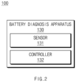
- FIG. 2 illustrates components of a battery diagnosis apparatus according to some embodiments.
- the battery diagnosis apparatus 130 may include a sensor 131 and a controller 132. However, without being limited thereto, some components may be omitted from the battery diagnosis apparatus 130 or other general-purpose components may be further included in the battery diagnosis apparatus 130.
- the senor 131 and the controller 132 may be electrically connected to each other through communication between devices such as a bus, general purpose input and output (GPIO), serial peripheral interface (SPI), mobile industry processor interface (MIPI), etc.
- devices such as a bus, general purpose input and output (GPIO), serial peripheral interface (SPI), mobile industry processor interface (MIPI), etc.
- GPIO general purpose input and output
- SPI serial peripheral interface
- MIPI mobile industry processor interface
- the sensor 131 of the battery diagnosis apparatus 130 may be configured to measure the voltage from the diagnosis target battery 120.
- a test cycle voltage is applied to the diagnosis target battery 120 by the charger/discharger 110, an output voltage may be generated in the diagnosis target battery 120 in response thereto, which may be measured by the sensor 131.
- the sensor 131 may include measuring means such as a voltmeter, an ammeter, a thermometer, etc.
- the controller 132 may have a structure for executing instructions that implement the operations of the battery diagnosis apparatus 130.
- the controller 132 may be implemented with an array of multiple logic gates or a general-purpose microprocessor for processing various operations, and may include a single processor or a plurality of processors.
- the controller 132 may be implemented in the form of at least one of a microprocessor, a CPU, a GPU, and an AP.
- the controller 132 may be configured separately from or integrally with a memory (not shown) configured to store instructions, and may process various operations by executing the instructions stored in the memory.
- the memory may store various data, instructions, mobile applications, computer programs, etc.
- the memory may be implemented in the form of non-volatile memory such as ROM, PROM, EPROM, EEPROM, flash memory, PRAM, MRAM, FRAM, etc., or volatile memory such as DRAM, SRAM, SDRAM, RRAM, HDD, SSD, SD, Micro- SD, etc., or may be implemented in the form of a combination thereof.
- the sensor 131 of the battery diagnosis apparatus 130 may be configured to measure the OCV from the diagnosis target battery 120 and generate first OCV data OCVs.
- the first OCV data OCVs may mean actually measured OCV values.
- the sensor 131 may measure the voltage from the diagnosis target battery 120, and derive the OCV of the diagnosis target battery 120 based on the measured voltage.
- OCV values may be measured n times for each of the m battery cells of the diagnosis target battery 120, and the first OCV data may include m*n OCV values.
- the controller 132 of the battery diagnosis apparatus 130 may be configured to obtain first state-of-charge data SOCs regarding the state of charge (SOC) of the diagnosis target battery 120 based on the first OCV data OCVs. For example, m*n OCV values of the first OCV data OCVs may be converted into m*n SOC values, and the first SOC data SOCs may include m*n SOC values. According to an embodiment, conversion of first OCV data OCVs into first SOC data SOCs may be performed based on an OCV-SOC mapping table.
- the controller 132 of the battery diagnosis apparatus 130 may be configured to derive second SOC data SOCests for estimating the SOC of the diagnosis target battery 120 based on the first SOC data SOCs.
- the first SOC data SOCs may mean a value converted from the first OCV data OCVs
- the second SOC data SOCests may be a value obtained by estimating the SOC of the diagnosis target battery 120 through an estimation process.
- the second SOC data SOCests may be estimated based on an average SOC value and a relative capacity value of each battery cell.
- the controller 132 of the battery diagnosis apparatus 130 may be configured to obtain second OCV data OCVests of the diagnosis target battery 120 based on the second SOC data SOCests.
- the second SOC data SOCests may include m*n estimated SOC values that may be converted into m*n estimated OCV values.
- the second OCV data OCVests may include m*n estimated OCV values.
- conversion of the second SOC data SOCests into the second OCV data OCVests may be performed based on an OCV-SOC mapping table, which may be the same as a table for converting the first OCV data OCVs into the first SOC data SOCs.
- the controller 132 of the battery diagnosis apparatus 130 may be configured to diagnose the state of the diagnosis target battery 120 based on the first OCV data OCVs and the second OCV data OCVests. According to an embodiment, the controller 132 of the battery diagnosis apparatus 130 may be configured to derive OCV deviation data OCVdevs based on a difference between the first OCV data OCVs and the second OCV data OCVests.
- the first OCV data OCVs may include m*n actually measured OCV values
- the second OCV data OCVests may contain m*n estimated OCV values
- a difference between the corresponding actually measured OCV value and estimated OCV value may produce m*n OCV deviation values.
- the OCV deviation data OCVdevs may include m*n OCV deviation values.
- the controller 132 of the battery diagnosis apparatus 130 may be configured to diagnose the state of the diagnosis target battery 120 based on the OCV deviation data OCVdevs. According to the embodiment, the controller 132 may diagnose whether abnormality occurs in a voltage behavior of each battery cell of the diagnosis target battery 120 by comparing the OCV deviation data OCVdevs or a change amount thereof with a normal range. In this way, voltage behavior abnormality may be detected even when there is no sudden voltage change due to cell disconnection, short circuit, etc.
- FIG. 3 illustrates an operating process of a battery diagnosis apparatus according to some embodiments.
- an operating process 300 of the battery management apparatus 130 may include a first process 310 to a sixth process 360.
- the first process 310 to the sixth process 360 may correspond to operations 1410 to 1460 of FIG. 14 described later.
- An OCV voltage of the diagnosis target battery 120 may be measured in the first process 310, the first OCV OCVs may be converted into the first SOC SOCs in the second process 320, and the estimated SOC data SOCests may be calculated based on the relative capacity value compared to the average SOC value in the third process 330.
- the second SOC data SOCests may be converted into the second OCV data OCVests in the fourth process 340, a deviation between the first OCV data OCVs and the second OCV data OCVests may be calculated in the fifth process 350, an OCV deviation change amount may be calculated based on the OCV deviation data OCVdevs in the sixth process 360, such that by comparing the OCV deviation change amount with a threshold value, voltage behavior abnormality of each cell of the diagnosis target battery 120 may be diagnosed.
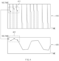
- FIG. 4 illustrates a process of measuring an OCV from a diagnosis target battery according to some embodiments.
- a charge/discharge profile 410 and an OCV graph 420 of the diagnosis target battery 120 are shown.
- the charge/discharge profile 410 may indicate a voltage measured from any one battery cell of the diagnosis target battery 120 when a charge/discharge cycle voltage is applied to the battery cell.
- peak values 411 in a measurement cycle of the charge/discharge profile 410 may be actually measured OCV values 421.
- the OCV graph 420 may include n actually measured OCV values 421.
- FIG. 5 illustrates a process of generating first OCV data according to some embodiments.
- the OCV graph 420 and first OCV data OCVs 510 of the diagnosis target battery 120 are shown.
- the OCV graph 420 may include n actually measured OCV values 421 for an i th battery cell, and the first OCV data OCVs 510 for m battery cells of the diagnosis target battery 120 may be m*n actually measured OCV values.
- the first OCV data OCVs 510 may be expressed in the form of a matrix with a size of m*n.
- the diagnosis target battery 120 may include a plurality of battery cells
- the first OCV data OCVs 510 may include a plurality of OCV values measured at a plurality of time points for each battery cell of the plurality of battery cells.
- FIG. 6 illustrates a process of converting first OCV data into second SoC data according to some embodiments.
- first OCV data OCVs 510 an OCV-SOC mapping table 610, and first SOC data SOCs 620 are shown.
- the controller 132 of the battery diagnosis apparatus 130 may be configured to convert the first OCV data OCVs 510 into the first OSC data SOCs 620 based on the OCV-SOC mapping table 610.
- the OCV-SOC mapping table 610 may mean a table which maps an OCV value of a vertical axis to an SOC value of a horizontal axis and records a mapping relationship therebetween.
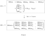
- FIG. 7 illustrates a process of calculating a relative capacity value of each battery cell based on an average SOC value according to some embodiments
- FIG. 8 illustrates a process of calculating a plurality of estimated OCV values based on a relative capacity value according to some embodiments.
- the first SOC data SOCs 620 an average SOC value SOCavg 710 for each of a plurality of time points 1, ..., n, relative capacity values A 720 and 730, a plurality of estimated SOC values SOCest i 810 for an ith battery cell, and second SOC data SOCests 820 of the diagnosis target battery 120 are shown.
- an average of the first SOC data SOCs 620 may be calculated, and as a result, the average SOC value SOCavg 710 may be calculated.
- the relative capacity value A 720 may be calculated based on the average SOC value SOCavg 710 and the first SOC data SOCs 620.
- the relative capacity value A 720 may be calculated.
- a pseudoinverse matrix (PINV) operation of the average SOCavg 710 may be performed.
- the pseudoinverse matrix may refer to a Moore-Penrose inverse matrix.
- the relative capacity value Ai 730 of the i th battery cell may include a slope component A slopei and an offset component A offseti .
- a plurality of estimated SOC values SOCesti 810 of the i th battery cell may be calculated based on the relative capacity value A i 730 and the average SOC value SOCavg 710 of the i th battery cell.
- the plurality of estimated SOC values SOCest i 810 of the ith battery cell may be calculated based on the slope component A slopei , the offset component A offseti , and the average SOC value SOCavg 710.
- the second SOC data SOCests 820 of the diagnosis target battery 120 may be calculated.
- the controller 132 of the battery diagnosis apparatus 130 may be configured to calculate the average SOC value SOCavg 710 of the plurality of SOC values converted from the plurality of OCV values for each battery cell, calculate the relative capacity value A i of each battery cell based on the average SOC value SOCavg 710, and calculate the plurality of estimated SOC values SOCest i of each battery cell at a plurality of time points based on the relative capacity value A i .
- the controller 132 of the battery diagnosis apparatus 130 may multiply the average SOC matrix SOC avg 1 1 SOC avg 2 1 SOC avg 3 1 ⁇ ⁇ SOC avgn 1 representing the average SOC values of the battery cells by the relative capacity matrix A to calculate the estimated SOC matrix SOCests indicating the plurality of estimated SOC values SOCest i 810 of each battery cell.
- FIG. 9 illustrates a process of generating second SOC data and second OCV data according to some embodiments.
- the first OCV data OCVs 910 may be converted into the first SOC data SOCs 920 based on the OCV-SOC mapping table 610.
- An average SOC value SOCavg 930 may be calculated based on the first SOC data SOCs 920.
- estimated SOC values SOCest 1 950 for the first battery cell may be calculated, and the OCV-SOC mapping table 610 may be applied thereto to calculate estimated OCV values OCVest 1 960 for the first battery cell.
- FIG. 10 illustrates a process of converting second SOC data into second OCV data according to some embodiments.
- FIG. 10 a process of converting second SOC data SOCests 820 of the diagnosis target battery 120 into second OCV data OCVests 1010 based on the OCV-SOC mapping table 610 is shown.
- the controller 132 of the battery diagnosis apparatus 130 may be configured to convert the second OCV data SOCests 820 into the second OCV data OCVests 1010 based on the OCV-SOC mapping table 610.
- the OCV-SOC mapping table 610 may be the same as a table used for converting the first OCV data OCVs 510 into the first SOC data SOCs 620.
- FIG. 11 illustrates a process of deriving OCV deviation data based on a difference between first OCV data and second OCV data according to some embodiments
- FIG. 12 illustrates a process of calculating a plurality of OCV deviation change amounts based on OCV deviation data according to some embodiments.
- a process of deriving OCV deviation data OCVdevs 1110 based on a difference between the first OCV data OCVs 510 and the second OCV data OCVests 1010 is shown, and referring to FIG. 12 , a process of calculating a plurality of OCV deviation change amounts 1210 and 1220 based on a difference between a value at a current time point and a value at a previous time point of the OCV deviation data OCVdevs 1110 is shown.
- the OCV deviation data OCVdevs 1110 may include a plurality of OCV deviation values OCVdev i1 , OCVdev i2 , ..., OCVdev in of each battery cell at a plurality of time points 1 to n.
- the controller 132 of the battery diagnosis apparatus 130 may be configured to calculate a plurality of OCV deviation change amounts OCVdiff i 1210 indicating a difference 1220 between an OCV deviation value at a current time point and an OCV deviation value at a previous time point based on the plurality of OCV deviation values OCVdev i1 , OCVdev i2 , ..., OCVdev in of each battery cell, and diagnose a state of each battery cell based on the plurality of OCV deviation change amounts OCVdiff i 1210 of each battery cell.
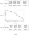
- FIG. 13 illustrates a process of diagnosing a state of each battery cell based on a plurality of OCV deviation change amounts according to some embodiments.
- OCV deviation change amounts OCVdiffs 1300 including the plurality of OCV deviation change amounts OCVdiff i 1210 of each battery cell may be derived, and voltage behavior abnormality of each battery cell of the diagnosis target battery 120 may be detected based on the OCV deviation change amount OCVdiffs 1300.
- an upper limit 1310 and a lower limit 1320 in a normal range may be set.
- an OCV deviation change amount of a specific battery cell exceeds the upper limit 1310 or falls short of the lower limit 1320 at a specific time point, it may be diagnosed that voltage behavior abnormality occurs in the corresponding battery cell at excess/shortfall time points.
- a battery cell having the OCV deviation change amount OCVdiffs 1300 may be diagnosed as an abnormal cell.
- the upper limit 1310 and the lower limit 1320 of the normal range may be changed depending on battery performance requirements.
- the normal range may be narrowed, and in the opposite case, the normal range may be widened.
- abnormality of the battery cell may be diagnosed based on the number and/or frequency that the battery performance requirements fall out of the normal range. For example, the number and/or frequency that the battery performance requirements fall out of the normal range may be compared with a threshold value.
- FIG. 14 illustrates operations of a battery diagnosis method according to some embodiments.
- the battery diagnosis method 1400 may include operations 1410 to 1460. However, without being limited thereto, some operations may be omitted and other general-purpose operations may be added, and operations of the battery diagnosis method 1400 may be executed in an order different from that shown.
- the battery diagnosis method 1400 may include operations processed in time series by the battery diagnosis apparatus 130. Therefore, matters described for the battery diagnosis apparatus 130 above, even omitted below, may be equally applied to the battery diagnosis method 1400.
- Operations 1410 to 1460 of the battery diagnosis method 1400 may be performed by the sensor 131 and the controller 132 of the battery diagnosis apparatus 130.
- the battery diagnosis apparatus 130 may generate first OCV data by measuring an OCV from a diagnosis target battery.
- the battery diagnosis apparatus 130 may obtain first SOC data regarding an SOC of a diagnosis target battery based on the first OCV data.
- the battery diagnosis apparatus 130 may derive second SOC data for estimating the SOC of the diagnosis target battery based on the first SOC data.
- the battery diagnosis apparatus 130 may obtain second OCV data of the diagnosis target battery based on the second SOC data.
- the battery diagnosis apparatus 130 may diagnose the state of the diagnosis target battery based on the first OCV data and the second OCV data.
- the battery diagnosis method 1400 may be implemented in the form of a computer program stored in a computer-readable storage medium. That is, the computer program may include instructions for implementing the battery diagnosis method 1400, and the instructions of the program may be stored in a computer-readable storage medium.
- the computer programs may include mobile applications.
- the computer-readable storage medium may include magnetic media such as hard disk, floppy disk, and magnetic tape, optical media such as compact disk read only memory (CD-ROM) and digital versatile disk (DVD), magneto-optical media such as floptical disk, and a hardware device especially configured to store and execute program instructions, such as read only memory (ROM), random access memory (RAM) and flash memory, etc.
- the computer program instructions may include a machine language code created by a complier and a high-level language code executable by a computer using an interpreter.
- Battery Diagnosis System 110 Charger/Discharger 120: Diagnosis Target Battery 130: Battery Diagnosis Apparatus 131: Sensor 132: Controller 140: Management Server
Landscapes
- Physics & Mathematics (AREA)
- General Physics & Mathematics (AREA)
- Engineering & Computer Science (AREA)
- Power Engineering (AREA)
- Secondary Cells (AREA)
- Tests Of Electric Status Of Batteries (AREA)
Applications Claiming Priority (3)
| Application Number | Priority Date | Filing Date | Title |
|---|---|---|---|
| KR20220120916 | 2022-09-23 | ||
| KR1020230102473A KR102690411B1 (ko) | 2022-09-23 | 2023-08-04 | 배터리 진단 장치 및 배터리 진단 방법 |
| PCT/KR2023/013537 WO2024063418A2 (fr) | 2022-09-23 | 2023-09-08 | Dispositif de diagnostic de batterie et procédé de diagnostic de batterie |
Publications (2)
| Publication Number | Publication Date |
|---|---|
| EP4560330A2 true EP4560330A2 (fr) | 2025-05-28 |
| EP4560330A4 EP4560330A4 (fr) | 2025-12-03 |
Family
ID=90454721
Family Applications (1)
| Application Number | Title | Priority Date | Filing Date |
|---|---|---|---|
| EP23868472.4A Pending EP4560330A4 (fr) | 2022-09-23 | 2023-09-08 | Dispositif de diagnostic de batterie et procédé de diagnostic de batterie |
Country Status (6)
| Country | Link |
|---|---|
| US (1) | US20250123334A1 (fr) |
| EP (1) | EP4560330A4 (fr) |
| JP (1) | JP2025530400A (fr) |
| KR (1) | KR102864813B1 (fr) |
| CN (1) | CN119790310A (fr) |
| WO (1) | WO2024063418A2 (fr) |
Family Cites Families (13)
| Publication number | Priority date | Publication date | Assignee | Title |
|---|---|---|---|---|
| KR100669470B1 (ko) * | 2005-12-22 | 2007-01-16 | 삼성에스디아이 주식회사 | 배터리의 soo 보정 방법 및 이를 이용한 배터리 관리시스템 |
| EP3136118B1 (fr) * | 2012-06-13 | 2018-01-31 | LG Chem, Ltd. | Appareil et procédé d'estimation de tension de batterie secondaire comprenant une matière de cathode mélangée |
| US10386418B2 (en) * | 2015-02-19 | 2019-08-20 | Mitsubishi Electric Corporation | Battery state estimation device |
| WO2016143728A1 (fr) * | 2015-03-06 | 2016-09-15 | 株式会社デンソー | Dispositif d'estimation d'état de batterie |
| JP6722036B2 (ja) * | 2015-12-17 | 2020-07-15 | ローム株式会社 | 充電式のバッテリの残量検出回路、それを用いた電子機器、自動車ならびに充電状態の検出方法 |
| KR102064459B1 (ko) * | 2017-01-05 | 2020-01-09 | 주식회사 엘지화학 | 이차 전지의 저전압 불량 검사 방법 및 장치 |
| EP3605121B1 (fr) * | 2017-03-31 | 2023-04-12 | Mitsubishi Electric Corporation | Dispositif d'estimation de l'état d'une batterie de stockage |
| KR102452548B1 (ko) * | 2017-04-18 | 2022-10-07 | 현대자동차주식회사 | 배터리 열화 상태 추정장치, 그를 포함한 시스템 및 그 방법 |
| KR102781907B1 (ko) * | 2019-11-28 | 2025-03-18 | 주식회사 엘지에너지솔루션 | 배터리 셀 이상 퇴화 진단 장치 및 방법 |
| JP7397693B2 (ja) * | 2020-01-28 | 2023-12-13 | 日置電機株式会社 | 測定装置及び蓄電デバイスの測定方法 |
| KR20220120916A (ko) | 2021-02-24 | 2022-08-31 | 주식회사 엘지에너지솔루션 | 전지 모듈 및 이를 포함하는 전지팩 |
| CN114264965B (zh) * | 2021-11-22 | 2025-09-02 | 深圳锂安技术有限公司 | 电池短路故障预警信息生成方法和装置、设备、介质 |
| KR20230102473A (ko) | 2021-12-30 | 2023-07-07 | 최성희 | 로봇 자동화형 드론 스테이션 |
-
2023
- 2023-09-08 WO PCT/KR2023/013537 patent/WO2024063418A2/fr not_active Ceased
- 2023-09-08 CN CN202380061103.6A patent/CN119790310A/zh active Pending
- 2023-09-08 EP EP23868472.4A patent/EP4560330A4/fr active Pending
- 2023-09-08 JP JP2025516003A patent/JP2025530400A/ja active Pending
-
2024
- 2024-07-22 KR KR1020240096137A patent/KR102864813B1/ko active Active
- 2024-12-20 US US18/990,295 patent/US20250123334A1/en active Pending
Also Published As
| Publication number | Publication date |
|---|---|
| EP4560330A4 (fr) | 2025-12-03 |
| CN119790310A (zh) | 2025-04-08 |
| US20250123334A1 (en) | 2025-04-17 |
| WO2024063418A3 (fr) | 2024-05-23 |
| KR102864813B1 (ko) | 2025-09-26 |
| WO2024063418A2 (fr) | 2024-03-28 |
| KR20240119021A (ko) | 2024-08-06 |
| JP2025530400A (ja) | 2025-09-11 |
Similar Documents
| Publication | Publication Date | Title |
|---|---|---|
| US11035905B1 (en) | Apparatus and method for testing performance of battery cell | |
| US10393813B2 (en) | On-board state of health monitoring of batteries using incremental capacity analysis | |
| US7197487B2 (en) | Apparatus and method for estimating battery state of charge | |
| US11644508B2 (en) | Method and apparatus for measuring state of battery | |
| US20110054816A1 (en) | Method of estimating the non-measurable characteristics of an electrochemical system | |
| Weng et al. | An open-circuit-voltage model of lithium-ion batteries for effective incremental capacity analysis | |
| EP4692815A1 (fr) | Appareil et procédé de diagnostic de batterie | |
| EP4632400A1 (fr) | Dispositif de prédiction de quantité de gaz généré dans une batterie et son procédé de fonctionnement | |
| EP4390418A1 (fr) | Appareil électronique et procédé avec estimation de l'état de la batterie | |
| US20230266400A1 (en) | Battery Diagnosing Apparatus and Method | |
| US20250123337A1 (en) | Battery diagnosis apparatus, battery diagnosis method and battery diagnosis system | |
| KR102690411B1 (ko) | 배터리 진단 장치 및 배터리 진단 방법 | |
| EP4560330A2 (fr) | Dispositif de diagnostic de batterie et procédé de diagnostic de batterie | |
| KR102926459B1 (ko) | 배터리의 퇴화 검사 장치 및 이의 동작 방법 | |
| CN104272127A (zh) | 用于确定二次电池的总容量损失的方法 | |
| EP4332598A1 (fr) | Estimation du vieillissement calendaire des cellules de batterie | |
| KR20240116302A (ko) | 배터리 온도 추정 장치 및 이의 동작 방법 | |
| KR20240101221A (ko) | 배터리 진단 장치 및 그의 동작 방법 | |
| EP4733781A1 (fr) | Appareil de diagnostic de batterie, procédé de diagnostic de batterie et système de diagnostic de batterie | |
| KR102831587B1 (ko) | 배터리 진단 장치 및 이의 동작 방법 | |
| CN120908680B (zh) | 检测方法、检测装置以及计算机可读存储介质 | |
| US20240201281A1 (en) | Battery Management Apparatus and Operating Method Thereof | |
| EP4711782A1 (fr) | Appareil de gestion de batterie et procédé de fonctionnement associé | |
| EP4679111A1 (fr) | Dispositif de diagnostic de batterie et son procédé de fonctionnement | |
| KR20250038515A (ko) | 배터리 진단 장치, 배터리 진단 방법 및 배터리 진단 시스템 |
Legal Events
| Date | Code | Title | Description |
|---|---|---|---|
| STAA | Information on the status of an ep patent application or granted ep patent |
Free format text: STATUS: THE INTERNATIONAL PUBLICATION HAS BEEN MADE |
|
| PUAI | Public reference made under article 153(3) epc to a published international application that has entered the european phase |
Free format text: ORIGINAL CODE: 0009012 |
|
| STAA | Information on the status of an ep patent application or granted ep patent |
Free format text: STATUS: REQUEST FOR EXAMINATION WAS MADE |
|
| 17P | Request for examination filed |
Effective date: 20250218 |
|
| AK | Designated contracting states |
Kind code of ref document: A2 Designated state(s): AL AT BE BG CH CY CZ DE DK EE ES FI FR GB GR HR HU IE IS IT LI LT LU LV MC ME MK MT NL NO PL PT RO RS SE SI SK SM TR |
|
| REG | Reference to a national code |
Ref country code: DE Ref legal event code: R079 Free format text: PREVIOUS MAIN CLASS: G01R0031360000 Ipc: G01R0031392000 |
|
| A4 | Supplementary search report drawn up and despatched |
Effective date: 20251030 |
|
| RIC1 | Information provided on ipc code assigned before grant |
Ipc: G01R 31/392 20190101AFI20251024BHEP Ipc: G01R 31/3835 20190101ALI20251024BHEP Ipc: G01R 31/396 20190101ALI20251024BHEP Ipc: G01R 31/367 20190101ALI20251024BHEP |
|
| DAV | Request for validation of the european patent (deleted) | ||
| DAX | Request for extension of the european patent (deleted) |