EP4560363A2 - Sicherheitsmechanismus zum vergleichen von messsignalen - Google Patents
Sicherheitsmechanismus zum vergleichen von messsignalen Download PDFInfo
- Publication number
- EP4560363A2 EP4560363A2 EP24213914.5A EP24213914A EP4560363A2 EP 4560363 A2 EP4560363 A2 EP 4560363A2 EP 24213914 A EP24213914 A EP 24213914A EP 4560363 A2 EP4560363 A2 EP 4560363A2
- Authority
- EP
- European Patent Office
- Prior art keywords
- light
- door leaf
- electrical signal
- field area
- module
- Prior art date
- Legal status (The legal status is an assumption and is not a legal conclusion. Google has not performed a legal analysis and makes no representation as to the accuracy of the status listed.)
- Pending
Links
Images


Classifications
-
- G—PHYSICS
- G01—MEASURING; TESTING
- G01V—GEOPHYSICS; GRAVITATIONAL MEASUREMENTS; DETECTING MASSES OR OBJECTS; TAGS
- G01V8/00—Prospecting or detecting by optical means
- G01V8/10—Detecting, e.g. by using light barriers
- G01V8/20—Detecting, e.g. by using light barriers using multiple transmitters or receivers
- G01V8/22—Detecting, e.g. by using light barriers using multiple transmitters or receivers using reflectors
-
- E—FIXED CONSTRUCTIONS
- E05—LOCKS; KEYS; WINDOW OR DOOR FITTINGS; SAFES
- E05F—DEVICES FOR MOVING WINGS INTO OPEN OR CLOSED POSITION; CHECKS FOR WINGS; WING FITTINGS NOT OTHERWISE PROVIDED FOR, CONCERNED WITH THE FUNCTIONING OF THE WING
- E05F15/00—Power-operated mechanisms for wings
- E05F15/70—Power-operated mechanisms for wings with automatic actuation
- E05F15/73—Power-operated mechanisms for wings with automatic actuation responsive to movement or presence of persons or objects
-
- E—FIXED CONSTRUCTIONS
- E05—LOCKS; KEYS; WINDOW OR DOOR FITTINGS; SAFES
- E05F—DEVICES FOR MOVING WINGS INTO OPEN OR CLOSED POSITION; CHECKS FOR WINGS; WING FITTINGS NOT OTHERWISE PROVIDED FOR, CONCERNED WITH THE FUNCTIONING OF THE WING
- E05F15/00—Power-operated mechanisms for wings
- E05F15/70—Power-operated mechanisms for wings with automatic actuation
-
- G—PHYSICS
- G01—MEASURING; TESTING
- G01J—MEASUREMENT OF INTENSITY, VELOCITY, SPECTRAL CONTENT, POLARISATION, PHASE OR PULSE CHARACTERISTICS OF INFRARED, VISIBLE OR ULTRAVIOLET LIGHT; COLORIMETRY; RADIATION PYROMETRY
- G01J1/00—Photometry, e.g. photographic exposure meter
- G01J1/02—Details
- G01J1/04—Optical or mechanical part supplementary adjustable parts
- G01J1/0407—Optical elements not provided otherwise, e.g. manifolds, windows, holograms, gratings
- G01J1/0411—Optical elements not provided otherwise, e.g. manifolds, windows, holograms, gratings using focussing or collimating elements, i.e. lenses or mirrors; Aberration correction
-
- G—PHYSICS
- G01—MEASURING; TESTING
- G01V—GEOPHYSICS; GRAVITATIONAL MEASUREMENTS; DETECTING MASSES OR OBJECTS; TAGS
- G01V8/00—Prospecting or detecting by optical means
- G01V8/10—Detecting, e.g. by using light barriers
- G01V8/12—Detecting, e.g. by using light barriers using one transmitter and one receiver
-
- G—PHYSICS
- G01—MEASURING; TESTING
- G01V—GEOPHYSICS; GRAVITATIONAL MEASUREMENTS; DETECTING MASSES OR OBJECTS; TAGS
- G01V8/00—Prospecting or detecting by optical means
- G01V8/10—Detecting, e.g. by using light barriers
- G01V8/20—Detecting, e.g. by using light barriers using multiple transmitters or receivers
-
- G—PHYSICS
- G02—OPTICS
- G02B—OPTICAL ELEMENTS, SYSTEMS OR APPARATUS
- G02B3/00—Simple or compound lenses
- G02B3/02—Simple or compound lenses with non-spherical faces
- G02B3/08—Simple or compound lenses with non-spherical faces with discontinuous faces, e.g. Fresnel lens
-
- E—FIXED CONSTRUCTIONS
- E05—LOCKS; KEYS; WINDOW OR DOOR FITTINGS; SAFES
- E05F—DEVICES FOR MOVING WINGS INTO OPEN OR CLOSED POSITION; CHECKS FOR WINGS; WING FITTINGS NOT OTHERWISE PROVIDED FOR, CONCERNED WITH THE FUNCTIONING OF THE WING
- E05F15/00—Power-operated mechanisms for wings
- E05F15/70—Power-operated mechanisms for wings with automatic actuation
- E05F15/73—Power-operated mechanisms for wings with automatic actuation responsive to movement or presence of persons or objects
- E05F2015/765—Power-operated mechanisms for wings with automatic actuation responsive to movement or presence of persons or objects using optical sensors
Definitions
- the present invention relates to a safety mechanism for comparing sensing signals, and more particularly to a mechanism that is disposed inside a light quantity sensor of an automatic passing apparatus and is applied to comparing and determining differences between an electrical signal stored in a processing unit and a changing electrical signal, so as to provide a safety sensing device that keeps door leaves open and prevents the door leaves from closing on people.
- An automatic passing apparatus is generally used in places where personnel or carriers frequently enter, leave, or approach, such as storehouses, passage partitions, banks, shopping malls, and offices.
- a sensing device disposed on a top portion of a door, the approaching, entering, or leaving of the personnel or the carriers can be sensed, and a motor is driven to enable opening of a door leaf or a rolling door of the automatic passing apparatus. After the personnel or the carriers pass through, the sensing device no longer senses their presence, and the door leaf or the rolling door of the automatic passing apparatus returns to being closed.
- a light sensing device is usually used for the sensing of the automatic passing apparatus, and an existing infrared sensing device is often used for dynamic sensing.
- a control module of the automatic passing apparatus does not have the function of storing and comparing door leaf electrical signals generated by reflection light of a door leaf light field. As such, when the sensed body is located at a position where the door leaf moves to be closed, the control module cannot guarantee that the door leaf is maintained in an opened state or that closing is performed in a safe manner.
- the present invention provides a safety mechanism for comparing sensing signals. Regardless of a dynamic or a static condition, the safety mechanism of the present invention (which is disposed in a light quantity sensor) can detect and determine in an accurate manner, such that a door leaf of an automatic passing apparatus can be kept in an opened position and have a safe and accurate closing operation.
- the safety mechanism includes: at least one emitting convex lens group, at least one light emitting module, at least one receiving convex lens group, at least one light receiving module, and at least one control module.
- the at least one emitting convex lens group includes one or more emitting convex lens.
- the at least one light emitting module includes one or more light emitting component.
- Each of the light emitting components is configured to project light to the respective emitting convex lens by a geometrical optics approach, so as to form a corresponding light field area and a corresponding luminous flux.
- the at least one receiving convex lens group includes one or more receiving convex lens.
- the at least one light receiving module includes one or more light receiving component and is a photoelectric conversion component.
- the luminous flux of the light field area is configured to reflect a corresponding one of reflection light depending on an environment, and is configured to reflect the corresponding one of the reflection light to the respective one or more light receiving components through the at least one receiving convex lens group by the geometrical optics approach, and is configured to convert the reflection light into a corresponding electrical signal.
- the at least one light receiving module is electrically connected to the at least one control module.
- the at least one control module includes one or more processing unit, and the processing unit includes an electronic circuit, a micro-controller (MCU), a memory (RAM), etc.
- the corresponding electrical signal converted by the light receiving component is input and stored in the processing unit.
- the at least one light receiving module is configured to output a static first environment electrical signal, and the first environmental electrical signal is stored to the processing unit of the at least one control module for comparison and reference.
- the at least one light receiving module is configured to generate a first changing electrical signal regardless of whether the sensed body is in a dynamic or a static state, and the first changing electrical signal is compared with the stored first environment electrical signal in the processing unit.
- the at least one control module is configured to enable the automatic passing apparatus to be in an opened state.
- a door leaf light emitting module and a door leaf light receiving module are configured to correspondingly project and sense a moving position of a door leaf of the automatic passing apparatus, so as to form a luminous flux of a door leaf light field area.
- the door leaf light receiving module is configured to generate a static second electrical signal of the door leaf, and the second static electrical signal is additionally stored in the processing unit of the at least one control module for comparison and reference.
- the door leaf light receiving module is configured to generate a second changing electrical signal of the door leaf regardless of whether the sensed body is in the dynamic or the static state, and the second changing electrical signal is compared with the stored second static electrical signal in the processing unit.
- the at least one control module is configured to enable the automatic passing apparatus to be in the opened state.
- a closing operation of the door leaf of the automatic passing apparatus is performed at a constant velocity, such that the door leaf reflects reflection light with regular changing fluctuations within an operation area of the door leaf; wherein the door leaf light receiving module is configured to output a third door leaf electrical signal, and the third door leaf electrical signal is additionally stored in the processing unit of the at least one control module.
- the third door leaf electrical signal generated from each closing operation of the door leaf is compared with the stored third door leaf electrical signal in the processing unit, and the processing unit of the at least one control module is configured to enable the door leaf of the automatic passing apparatus to complete a closing action when a same regularly changing fluctuation is detected.
- the number of the light emitting component is plural, and the light emitting components are electrically connected to a first circuit board.
- a quantity of the light receiving component is plural, and the light receiving components are electrically connected to a second circuit board.
- the light receiving components are electrically connected to the at least one control module through the second circuit board.
- the at least one light emitting module is correspondingly disposed at a rear side of the at least one emitting convex lens group, and light emitted by the light emitting component is projected to a passing environment through the emitting convex lens, so as to form the light field area corresponding to the luminous flux.
- the at least one light receiving module is correspondingly disposed at a rear side of the at least one receiving convex lens group, and the light reflected back by the luminous flux in the light field area is reflected to the light receiving component through the receiving convex lens.
- the emitting convex lens and the receiving convex lens are each a Fresnel lens.
- the luminous flux of the light field area reflects static reflection light when the sensed body is not in the light field area, and the static reflection light is converted into the first static electrical signal and is stored in a database of the processing unit for comparison.
- Each reflection light of the luminous flux of the light field area correspondingly represents one of various states of the sensed body, and the states of the sensed body include the dynamic state and the static state.
- a database of the processing unit stores the data of various door leaf electrical signals converted from the reflection light of the luminous flux in the door leaf light field area as the door leaf of the automatic passing apparatus is in a fully-opened state, a fully-closed state, and a moving state for comparison.
- a database of the processing unit stores various electrical signals for comparing a variation of the reflection light of the luminous flux in the light field area.
- Each type of the variation of the reflection light of the luminous flux in the light field area correspondingly represents various states of the sensed body, and the states of the sensed body include the dynamic state and the static state.
- the at least one light emitting module includes at least one visible light emitting module, and the at least one visible light emitting module has one or more visible light emitting component and one or more visible light emitting convex lens. Visible light is emitted by the at least one visible light emitting module by the geometrical optics approach to generate at least one visible light projection point.
- the at least one visible light emitting module is a laser emitting module.
- a laser emitting component and the visible light emitting convex lens integrally cover an apparatus, and emitting at least one laser projection point.
- the visible light module is configured to correspondingly project on a position at an inner side of a front edge of the light field area, and is configured to indicate relative positions of the light field area and the automatic passing apparatus.
- the safety mechanism includes: at least one emitting convex lens group, at least one light emitting module, at least one receiving convex lens group, at least one light receiving module, and at least one control module.
- the at least one emitting convex lens group includes one or more emitting convex lens.
- the at least one light emitting module includes one or more light emitting component, and each of the light emitting components is configured to project light to the respective emitting convex lens by a geometrical optics approach, so as to form a corresponding light field area and a corresponding luminous flux.
- the at least one receiving convex lens group includes one or more receiving convex lens.
- the at least one light receiving module includes one or more light receiving components and is a photoelectric conversion component.
- the luminous flux of the light field area is configured to reflect a corresponding one of reflection light depending on an environment, and is configured to reflect to the respective light receiving component through the at least one receiving convex lens group by the geometrical optics approach, and is configured to convert the reflection light into a corresponding electrical signal.
- the at least one light receiving module is electrically connected to the at least one control module.
- the at least one control module includes a processing unit, and the processing unit includes an electronic circuit, a micro-controller (MCU), a memory (RAM), etc.
- the corresponding electrical signal converted by the light receiving component is input and stored in the processing unit.
- the at least one light receiving module is configured to generate a first environment electrical signal, and the first environmental electrical signal is stored in the processing unit of the at least one control module for comparison and reference.
- the at least one light receiving module is configured to generate a first changing electrical signal regardless of whether the sensed body is in a dynamic or a static state, and the first changing electrical signal is compared with the first environment electrical signal that is stored in the processing unit.
- the at least one control module is configured to enable the automatic passing apparatus to be in an opened state.
- yet another one of the technical aspects adopted by the present invention is to provide a safety mechanism for comparing sensing signals which is disposed in a light quantity sensor of an automatic passing apparatus.
- the safety mechanism includes: at least one emitting convex lens group, at least one light emitting module, at least one receiving convex lens group, at least one light receiving module, and at least one control module.
- the at least one emitting convex lens group includes one or more emitting convex lens.
- the at least one light emitting module includes one or more light emitting components. The light emitting component is configured to project light to the respective emitting convex lens by the geometrical optics approach, so as to form a corresponding light field area and a corresponding luminous flux.
- the at least one receiving convex lens group includes one or more receiving convex lens.
- the at least one light receiving module includes a light receiving component and is a photoelectric conversion component.
- the luminous flux of the light field area is configured to reflect a corresponding one of reflection light depending on an environment, and is configured to reflect to the respective light receiving component through the at least one receiving convex lens group by the geometrical optics approach, and is configured to convert the reflection light into a corresponding electrical signal.
- the at least one light receiving module is electrically connected to the at least one control module.
- the at least one control module includes at least one processing unit, and the processing unit includes an electronic circuit, a micro-controller (MCU), a memory (RAM), etc.
- the corresponding electrical signal converted by the light receiving component is input and stored in the processing unit.
- a door leaf light emitting module and a door leaf light receiving module are configured to correspondingly project and sense a moving position of a door leaf of the automatic passing apparatus, so as to form a luminous flux of a door leaf light field area.
- the door leaf light receiving module is configured to generate a second static electrical signal of the door leaf, and the second static electrical signal is additionally stored in the processing unit of the at least one control module for comparison and reference.
- the door leaf light receiving module is configured to generate a second changing electrical signal of the door leaf regardless of whether the sensed body is in the dynamic state or the static state, and the second changing electrical signal is compared with the stored second static electrical signal in the processing unit.
- the at least one control module is configured to enable the automatic passing apparatus to be in the opened state.
- a closing operation of the door leaf of the automatic passing apparatus is performed at a constant velocity, such that the door leaf reflects a reflection light with regular variations within an operation area of the door leaf.
- the door leaf light receiving module is configured to output a third door leaf electrical signal, and the third door leaf electrical signal is additionally stored in the processing unit of the at least one control module.
- the third door leaf electrical signal generated from closing operation of the door leaf is compared with the stored door leaf electrical signal in the processing unit.
- the processing unit of the at least one control module is configured to enable the door leaf of the automatic passing apparatus to complete a closing action when a same regularly changing fluctuation is detected.
- the safety mechanism for comparing the sensing signals includes at least one light emitting module, at least one emitting convex lens group, at least one light receiving module, at least one receiving convex lens group, and at least one control module.
- the at least one light emitting module includes one or more light emitting component.
- the light emitting component is configured to emit light, and the light is projected through an emitting convex lens, so as to form a light field area and a corresponding luminous flux in a passing environment.
- the at least one light receiving module includes one or more light receiving component, and the light receiving component is configured to receive reflection light in the light field area through a receiving convex lens.
- the at least one control module includes a processing unit, and the light receiving component receives and converts the reflection light in the light field area into electrical signals for transmission to the processing unit.
- the light receiving component receives and converts the reflection light in the light field area into electrical signals for transmission to the processing unit.
- the light field area of the present invention is within an operating path area of the door leaf of the automatic passing apparatus.
- a door leaf receiving module When the door leaf is fully opened and no sensed body is present in a door leaf light field area, a door leaf receiving module will generate a second static electrical signal of the door leaf, and the second static electrical signal is further stored in the processing unit of the at least one control module for comparison and reference. Later, when the door leaf is fully opened and the sensed body is present in the door leaf light field, a second changing electrical signal will be generated regardless of a dynamic or a static state. By comparing the difference between these two signals, the at least one control module enables the automatic passing apparatus to be kept in an opened state.
- the third door leaf electrical signal is stored in the processing unit of the at least one control module. Later, the third door leaf electrical signal generated from each closing operation of the door leaf will be compared with the stored third door leaf electrical signal, and the at least one control module enables the door leaf of the automatic passing apparatus to complete a safe closing action when a same regularly changing fluctuation is detected between said two door leaf electrical signals.
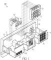
- a first embodiment of the present invention provides a safety mechanism 100 for comparing sensing signals, and the mechanism requires a mechanism correspondingly disposed inside a light quantity sensor 500.
- a casing size and an appearance of said sensor can be designed based on practical requirements.
- a detecting device is to be disposed in a passing area of an automatic passing apparatus (such as an electric automatic door and an electric rolling door).
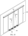
- the detecting device is disposed in the automatic passing apparatus 200 (as shown in FIG. 6 to FIG. 10 ), and the automatic passing apparatus 200 can be the electric automatic door or the electric rolling door.
- the automatic passing apparatus 200 is the electric automatic door
- the safety mechanism 100 sensing signal is disposed in the mechanism inside the light quantity sensor mentioned above, and is disposed above the automatic apparatus 200.
- the safety mechanism 100 includes at least one light emitting module 1-1, at least one visible light emitting module 1-2, at least one light receiving module 2, and at least one control module 3.
- the (infrared) light emitting module 1-1, the visible light emitting module 1-2, and the (infrared) light receiving module 2 are provided in the present embodiment, and the light emitting module 1-1 and the light receiving module 2 are spaced apart from each other.
- the quantity and the position of the light emitting module 1-1 and the light receiving module 2 are not limited, and can be changed as needed.
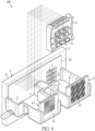
- the safety mechanism 100 can be without devices relevant to the visible light emitting module 1-2 (as shown in FIG. 4 and FIG. 5 ).
- the light emitting module 1-1 includes at least one light emitting component 11, and the quantity of the at least one light emitting component 11 is plural in the present embodiment.
- the light emitting components 11 can be electrically connected to a first circuit board 12, so as to form a modular design.
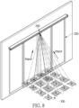
- the light emitting component 11 can project light and form a light field area 300 (as shown in FIG. 6 ), and generate a corresponding luminous flux.
- the light field area 300 is projected on the passing area of the automatic passing apparatus 200, and the light field area 300 can be separately or simultaneously projected on the passing area inside or outside the door of the automatic passing apparatus 200 as needed.
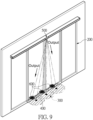
- the light emitting module 1-1 can be an infrared light emitting module, and is configured to emit visible light projection points 600 (as shown in FIG. 7 ) with the visible light emitting module 1-2, so as to indicate the position of the light field area 300 clearly (as shown in FIG. 7 ).
- the visible light emitting module 1-2 is disposed at a left side
- the light emitting module 1-1 (which is the infrared light emitting module) is disposed at a middle position.
- the light emitting module 1-1 includes the at least one light emitting component 11, and the quantity of the at least one light emitting component 11 is plural in the present embodiment.
- the light emitting components 11 can be electrically connected to the first circuit board 12, so as to form a modular design.
- the light emitting component 11 can project light and form the light field area 300 (as shown in FIG. 7 ).
- the light field area 300 is located in a door leaf operating passage of the automatic passing apparatus 200, and a corresponding luminous flux is generated.
- the light field area 300 can be separately or simultaneously projected on the passing area inside or outside the door of the automatic passing apparatus 200 as needed.
- the visible light emitting module 1-2 includes at least one visible light emitting component 13, and the visible light emitting component 13 (which can be an LED component or a laser component) can project the visible light projection points 600 in the door leaf operating passage of the automatic passing apparatus 200 (as shown in FIG. 7 ).
- the position of a front edge of the projected light field area 300 can be indicated synchronously, or the position of the front edge of the light field area in the door leaf operating passage of the automatic passing apparatus 200 can be indicated.
- the light receiving module 2 at a right side includes at least one light receiving component 21, and the quantity of the at least one light receiving component 21 is plural in the present embodiment.
- the light receiving components 21 can be electrically connected to a second circuit board 22, so as to form a modular design.
- the light receiving component 21 is configured to receive reflection light reflected back by the luminous flux in the light field area 300 (as shown in FIG. 8 ). Based on whether or not a sensed body is in the light field area, the reflection light of the luminous flux will have a corresponding variation.
- each light emitting module 1-1 is correspondingly provided with an emitting convex lens group 4-1.
- the emitting convex lens group 4-1 includes at least one emitting convex lens 41, which can be a Fresnel lens.
- the emitting convex lens 41 can be disposed in front of the light emitting components 11 based on the requirement of geometrical optics. Light beams emitted by the light emitting components 11 are projected to the emitting convex lens 41, and are correspondingly projected to a passing detection area of the automatic passing apparatus 200, so as to form the light field area 300.
- each visible light emitting module 1-2 is provided with a visible light emitting convex lens group 4-2, which includes at least one visible light emitting convex lens 42 that can be a Fresnel lens.
- the visible light emitting convex lens 42 can be disposed in front of the visible light emitting components 13 based on the requirement of geometrical optics, and visible light projected by the visible light emitting components 13 can be correspondingly projected to the visible light emitting convex lens 42.
- the visible light emitting module 1-2 can be a laser emitting module 1-3, and the laser emitting component and the visible light emitting convex lens can integrally cover an apparatus (as shown in FIG. 3 ).
- the visible light module is configured to correspondingly project to the front edge of the visible light projection points 600 in the light field area 300 (as shown in FIG. 7 and FIG. 9 ).
- each light receiving module 2 is correspondingly provided with a receiving convex lens group 5, and the receiving convex lens group 5 includes at least one receiving convex lens 51.
- the reflection light reflected back in the light field area 300 (as shown in FIG. 8 ) can be reflected to the light receiving component 21 through the receiving convex lens 51.
- the light receiving module 2 is electrically connected to the control module 3, and the light receiving component 21 can be electrically connected to the control module 3 by the second circuit board 22.
- the control module 3 includes a processing unit 31, which includes an electrical circuit, a micro-controller unit (MCU), a memory (RAM), etc.
- the light receiving component 21 is configured to receive the reflection light reflected back by the luminous flux in the light field area 300, and the reflection light is converted into an electrical signal by a photoelectric conversion unit (such as an infrared sensing LED) and sent to the processing unit 31 of the control module 3.
- the variation of the reflection light in the light field area 300 (as shown in FIG. 8 ) can be used to determine whether or not a sensed body (such as personnel or an object) enters the light field area, so as to keep the door leaf of the automatic passing apparatus 200 opened or switch off the control thereof.
- Reflection light beams of multiple ones of the light field area 300 are converted into electrical signals and stored in a memory database of the processing unit 31 for comparison.
- the database is pre-stored with states of the sensed body (such as personnel or an object) that represent the different light field areas 300, and each light field area 300 can correspondingly represent one of various states of the sensed body (such as personnel or an object).
- the states of the sensed body includes a dynamic state and a static state of the sensed body (such as personnel or an object), which are used to determine whether or not the sensed body (such as personnel or an object) enters the light field area.
- a static first electrical signal is generated and stored in the processing unit 31 of the control unit 3, and then the variation of the reflection light in the light field area 300 can be utilized. If the sensed body enters the light field area 300 (whether dynamically or statically), changing or fluctuated reflection light will be generated, and will be converted into a changing electrical signal by the light receiving component 21. The electrical signal is input into the processing unit 31 of the control module 3, and is compared with the stored static first electrical signal, so as to provide the control of keeping the automatic passing apparatus opened or closed.
- the variation of the reflection light in the light field area 300 can be used to determine whether or not a sensed body (such as personnel or an object) enters the light field area regardless of whether the sensed body is in the dynamic state or the static state.
- one single light receiving module 2 is used for receiving the reflection light reflected back from the light field area 300.
- the visible light emitting module is omitted.
- the safety mechanism 100 can also be used for providing safety light anti-pinch protection function. If the light emitting module 1-1 and the light receiving module 2 are configured to project in the area where the door leaf of the automatic passing apparatus moves, a closing operation of the door leaf that is performed at a constant velocity can also be sensed, and a third door leaf electrical signal of regular door leaf reflection light will be generated and stored in the processing unit 31 of the control module 3. The stored third door leaf electrical signal can be used for comparing with the third door leaf electrical signal generated after the closing operation of the door leaf. If in the closed state, the third door leaf electrical signal has the reflection light with the same regular pattern, the processing unit 31 of the control module 3 can command the door leaf of the automatic passing apparatus to complete a closing action.
- both of the door leaf light emitting module 1-1 and door leaf light receiving module 2 are configured to only correspondingly project and sense the position of a door leaf operating path 400 of the automatic passing apparatus, and a luminous flux of the light field of another door leaf operating area is formed.
- the door leaf light receiving module 2 will generate a second static electrical signal of the door leaf, which is stored to the processing unit 31 of the control module 3 for comparison and reference.
- the door leaf light receiving module 2 will generate a second changing electrical signal of the door leaf, and the two second electrical signals are compared in the processing unit. If waveforms of the two electrical signals are different, the control module 3 will command the automatic passing apparatus 200 to be in the opened state. Since the closing operation of the door leaf of the automatic passing apparatus 200 is performed at a constant velocity, the operating door leaf is configured to reflect reflection light with regular variation in the door leaf operating path 400.
- the door leaf light receiving module 2 is configured to output the third door leaf electrical signal, which is further stored in the processing unit 31 of the control module 3.
- the third door leaf electrical signal generated from each closing operation of the door leaf will be compared with the stored third door leaf electrical signal in the processing unit 31. If the two third door leaf electrical signals have the fluctuation with the same regular variation, the processing unit 31 of the control module 3 can command the door leaf in the door leaf operating path 400 to complete the closing action.
- the safety mechanism for comparing the sensing signals includes at least one light emitting module, at least one light receiving module, and a control module.
- the light emitting module includes one or more light emitting component, and the light emitting component is configured to emit light and form a light field area and a corresponding luminous flux in a passing path of an automatic passing apparatus by a geometrical optics approach.
- the control module includes a processing unit. After the light receiving component receives reflection light reflected back in the light field area, the reflection light is converted into an electrical signal and is sent to the processing unit.
- the processing unit is configured to determine whether or not a sensed body enters the light field area, so as to provide control of opening and closing of the automatic passing apparatus. Accordingly, in the present invention, the variation of the reflection light in the light field area is utilized for accurate detection and determination. Even if the sensed body is in a static state, a door leaf can still be kept in an opened position, such that a safe and reliable closing operation of the door leaf can be ensured, and an improved safety protection effect can be achieved.
- the light field area of the present invention can be located in a door leaf operating path of the automatic passing apparatus.
- the variation of the reflection light in the light field area whether or not the sensed body enters the door leaf operating path of the automatic passing apparatus can be determined.
- whether the sensed body in the door leaf operating path of the automatic passing apparatus is the automatic passing apparatus itself, personnel, or an object can also be determined, so as to provide safety light anti-pinch protection function.
- the light field area of the present invention can be located in an operating path of the automatic passing apparatus.
- a closing operation of the door leaf is performed at a constant velocity, such that door leaf reflection light with regular variations and a third door leaf electrical signal are generated and stored in the processing unit of the control module.
- the third door leaf electrical signal generated in each closed state of the door leaf is input into the processing unit, and is compared with the stored third door leaf electrical signal mentioned above. If the two door leaf electrical signals have a same regularly changing fluctuation, the control module will command the door leaf of the automatic passing apparatus to complete a closing action.
Landscapes
- Physics & Mathematics (AREA)
- General Physics & Mathematics (AREA)
- Life Sciences & Earth Sciences (AREA)
- General Life Sciences & Earth Sciences (AREA)
- Geophysics (AREA)
- Optics & Photonics (AREA)
- Spectroscopy & Molecular Physics (AREA)
- Power-Operated Mechanisms For Wings (AREA)
- Geophysics And Detection Of Objects (AREA)
Applications Claiming Priority (1)
| Application Number | Priority Date | Filing Date | Title |
|---|---|---|---|
| TW112145473A TWI863717B (zh) | 2023-11-24 | 2023-11-24 | 比對感測訊號的安全機構 |
Publications (2)
| Publication Number | Publication Date |
|---|---|
| EP4560363A2 true EP4560363A2 (de) | 2025-05-28 |
| EP4560363A3 EP4560363A3 (de) | 2025-08-13 |
Family
ID=93590628
Family Applications (1)
| Application Number | Title | Priority Date | Filing Date |
|---|---|---|---|
| EP24213914.5A Pending EP4560363A3 (de) | 2023-11-24 | 2024-11-19 | Sicherheitsmechanismus zum vergleichen von messsignalen |
Country Status (5)
| Country | Link |
|---|---|
| US (1) | US20250172029A1 (de) |
| EP (1) | EP4560363A3 (de) |
| JP (1) | JP7801793B2 (de) |
| CN (1) | CN120044622A (de) |
| TW (1) | TWI863717B (de) |
Family Cites Families (19)
| Publication number | Priority date | Publication date | Assignee | Title |
|---|---|---|---|---|
| GB9120267D0 (en) * | 1991-09-23 | 1991-11-06 | Memco Med Ltd | Lift door apparatus |
| JPH09264956A (ja) * | 1996-03-28 | 1997-10-07 | Sanwa Shutter Corp | 超音波センサ装置 |
| JPH11304922A (ja) * | 1998-02-17 | 1999-11-05 | Ricoh Opt Ind Co Ltd | 物体検知装置 |
| JP4164244B2 (ja) * | 2001-06-20 | 2008-10-15 | ヒースト株式会社 | 自動ドアの開閉制御方法 |
| JP2003027835A (ja) * | 2001-07-11 | 2003-01-29 | Nabco Ltd | 自動ドア用安全装置 |
| JP2006328853A (ja) * | 2005-05-27 | 2006-12-07 | Nabtesco Corp | 扉用複合センサ及び自動ドアシステム |
| JP5092078B2 (ja) * | 2006-06-28 | 2012-12-05 | オプテックス株式会社 | 物体検出装置 |
| JP5651837B2 (ja) * | 2010-03-17 | 2015-01-14 | 旭光電機株式会社 | 物体検出装置 |
| JP2012001969A (ja) * | 2010-06-16 | 2012-01-05 | Kyokko Electric Co Ltd | 自動扉及び自動扉用の自走ユニット |
| JP2013238087A (ja) * | 2012-05-17 | 2013-11-28 | Optex Co Ltd | 簡易型通行制限装置 |
| JP6676295B2 (ja) * | 2015-07-01 | 2020-04-08 | 北陽電機株式会社 | 自動ドア制御システム及び測距装置 |
| JP2020026688A (ja) * | 2018-08-13 | 2020-02-20 | ナブテスコ株式会社 | 検知状態記録装置、ズレ検出装置、自動ドア制御装置、自動ドアシステム及びズレ検出システム |
| JP7353641B2 (ja) * | 2019-12-25 | 2023-10-02 | オプテックス株式会社 | ドア開閉制御システム |
| WO2021199887A1 (ja) * | 2020-03-31 | 2021-10-07 | ナブテスコ株式会社 | 自動ドアシステム、センサの設定支援装置、センサ、設定支援システム、センサシステム、センサの設定支援方法、及びセンサの設定支援プログラム |
| JP7549862B2 (ja) * | 2020-05-29 | 2024-09-12 | ヒースト株式会社 | 扉開閉用制御装置 |
| JP7455019B2 (ja) * | 2020-07-27 | 2024-03-25 | ナブテスコ株式会社 | 自動ドア装置、取り付け高さ推定装置、取り付け高さ推定方法、および取り付け高さ推定プログラム |
| TWI797556B (zh) * | 2021-02-09 | 2023-04-01 | 豐菱電機有限公司 | 感測器光學同軸的發射模組 |
| CN115704920A (zh) * | 2021-08-06 | 2023-02-17 | 丰菱电机有限公司 | 可调变光场范围和具备高效能发射的通行传感器 |
| WO2023141880A1 (zh) * | 2022-01-27 | 2023-08-03 | 许俊甫 | 主动式传感器高效能光场投射的装置 |
-
2023
- 2023-11-24 TW TW112145473A patent/TWI863717B/zh active
-
2024
- 2024-01-05 CN CN202410020779.7A patent/CN120044622A/zh active Pending
- 2024-04-22 JP JP2024069353A patent/JP7801793B2/ja active Active
- 2024-11-04 US US18/935,878 patent/US20250172029A1/en active Pending
- 2024-11-19 EP EP24213914.5A patent/EP4560363A3/de active Pending
Also Published As
| Publication number | Publication date |
|---|---|
| CN120044622A (zh) | 2025-05-27 |
| TW202521834A (zh) | 2025-06-01 |
| EP4560363A3 (de) | 2025-08-13 |
| JP2025085579A (ja) | 2025-06-05 |
| TWI863717B (zh) | 2024-11-21 |
| JP7801793B2 (ja) | 2026-01-19 |
| US20250172029A1 (en) | 2025-05-29 |
Similar Documents
| Publication | Publication Date | Title |
|---|---|---|
| US4794248A (en) | Detection device having energy transmitters located at vertically spaced apart points along movable doors | |
| US7045764B2 (en) | Passive detection system for detecting a body near a door | |
| US7448548B1 (en) | Pulsed wireless directional object counter | |
| US5634846A (en) | Object detector for air conditioner | |
| EP1126430A2 (de) | Sicherheitssensor mit Sabotage-Feststellungsfähigkeit | |
| US5489892A (en) | Infrared human detector not barred by an intervening obstruction | |
| EP0070883B1 (de) | Fotoelektrischer hindernisdetektor für fahrstuhltüren | |
| JP3779644B2 (ja) | 自動ドア装置及びそれのタッチセンサ | |
| NL1003500C2 (nl) | Bewakingssysteem met lichtgeleidende middelen. | |
| KR102133732B1 (ko) | 외부감지 투시 도어 및 이를 가지는 외부감지 투시 보관함 | |
| US4539474A (en) | Optical switch for an automatic door | |
| WO2001024118A1 (en) | Counting apparatus | |
| US20070080225A1 (en) | Medium processing device | |
| EP4560363A2 (de) | Sicherheitsmechanismus zum vergleichen von messsignalen | |
| US20080074652A1 (en) | Retroreflector-based system and method for detecting intrusion into a restricted area | |
| DE69707888D1 (de) | Anschlagdetektor für industrietore | |
| HU218404B (hu) | Ajtóérzékelő rendszerek | |
| US20120218107A1 (en) | Entity detection system and method for monitoring an area | |
| JP3090354B2 (ja) | 測距式侵入者検知器 | |
| JP3337872B2 (ja) | 物体検知装置 | |
| JP3099248B2 (ja) | 測距式侵入者検知器 | |
| CA2430337A1 (en) | System and method for optically sensing motion of objects | |
| GB2174194A (en) | Monitoring a space | |
| JPH0719024Y2 (ja) | 自動ドア用センサ | |
| JPH0430552Y2 (de) |
Legal Events
| Date | Code | Title | Description |
|---|---|---|---|
| PUAI | Public reference made under article 153(3) epc to a published international application that has entered the european phase |
Free format text: ORIGINAL CODE: 0009012 |
|
| STAA | Information on the status of an ep patent application or granted ep patent |
Free format text: STATUS: THE APPLICATION HAS BEEN PUBLISHED |
|
| AK | Designated contracting states |
Kind code of ref document: A2 Designated state(s): AL AT BE BG CH CY CZ DE DK EE ES FI FR GB GR HR HU IE IS IT LI LT LU LV MC ME MK MT NL NO PL PT RO RS SE SI SK SM TR |
|
| PUAL | Search report despatched |
Free format text: ORIGINAL CODE: 0009013 |
|
| AK | Designated contracting states |
Kind code of ref document: A3 Designated state(s): AL AT BE BG CH CY CZ DE DK EE ES FI FR GB GR HR HU IE IS IT LI LT LU LV MC ME MK MT NL NO PL PT RO RS SE SI SK SM TR |
|
| RIC1 | Information provided on ipc code assigned before grant |
Ipc: G01V 8/22 20060101AFI20250709BHEP |
|
| STAA | Information on the status of an ep patent application or granted ep patent |
Free format text: STATUS: REQUEST FOR EXAMINATION WAS MADE |
|
| 17P | Request for examination filed |
Effective date: 20251210 |