EP4560411A1 - Dispositif d'affichage comprenant un mécanisme d'accouplement avec un mouvement horloger - Google Patents
Dispositif d'affichage comprenant un mécanisme d'accouplement avec un mouvement horloger Download PDFInfo
- Publication number
- EP4560411A1 EP4560411A1 EP23211817.4A EP23211817A EP4560411A1 EP 4560411 A1 EP4560411 A1 EP 4560411A1 EP 23211817 A EP23211817 A EP 23211817A EP 4560411 A1 EP4560411 A1 EP 4560411A1
- Authority
- EP
- European Patent Office
- Prior art keywords
- wheel
- display device
- rotation
- display
- driven
- Prior art date
- Legal status (The legal status is an assumption and is not a legal conclusion. Google has not performed a legal analysis and makes no representation as to the accuracy of the status listed.)
- Pending
Links
Images

Classifications
-
- G—PHYSICS
- G04—HOROLOGY
- G04B—MECHANICALLY-DRIVEN CLOCKS OR WATCHES; MECHANICAL PARTS OF CLOCKS OR WATCHES IN GENERAL; TIME PIECES USING THE POSITION OF THE SUN, MOON OR STARS
- G04B19/00—Indicating the time by visual means
- G04B19/20—Indicating by numbered bands, drums, discs, or sheets
- G04B19/21—Drums
-
- G—PHYSICS
- G04—HOROLOGY
- G04B—MECHANICALLY-DRIVEN CLOCKS OR WATCHES; MECHANICAL PARTS OF CLOCKS OR WATCHES IN GENERAL; TIME PIECES USING THE POSITION OF THE SUN, MOON OR STARS
- G04B13/00—Gearwork
-
- G—PHYSICS
- G04—HOROLOGY
- G04B—MECHANICALLY-DRIVEN CLOCKS OR WATCHES; MECHANICAL PARTS OF CLOCKS OR WATCHES IN GENERAL; TIME PIECES USING THE POSITION OF THE SUN, MOON OR STARS
- G04B33/00—Calibers
Definitions
- the invention relates to the field of watchmaking and in particular to watch movements.
- the invention relates in particular to a display device comprising a coupling mechanism with a watch movement.
- the relative positioning of a display with respect to a reference frame such as another display, a window or another fixed structure is particularly important since it is a visible element.
- the problem of relative positioning of displays is always difficult to resolve, any misalignment, even minimal, being very visible to the user. Since the correct positioning of a display is an important guarantee of quality, an inappropriate positioning of a display can be very detrimental to the image of a watch brand.
- the displays must therefore be indexed very precisely in relation to a given reference frame, generally formed by a structure of the watch movement or by another display. This indexing can however pose difficulties in integrating the display within the kinematic chain of the watch movement, during the assembly of the watch movement, in particular at the interface with a drive mechanism intended to transmit the energy of the watch movement to the display.
- the present invention aims to overcome this drawback by making it possible to simply index a display to a drive mechanism of a watch movement.
- the invention may further comprise one or more of the following features, taken individually or in any technically possible combination.
- the coupling mechanism comprises a support on which the transmission wheel is fixed in a rotatable manner, the support being configured to occupy a rotatable state around the axis of rotation of the driving wheel and a stationary state in which it is held in position by a locking member.
- the transmission wheel forms a satellite of the driven wheel and the driving wheel is formed by a crown comprising internal teeth.
- the driving wheel and the driven wheel are arranged coaxially.
- the support has two radial arms, one of which carries the transmission wheel and the other of which is held by clamping in a notch of the structure of the watch movement by the locking member when the support is in the stationary state.
- one of the arms comprises an adjustment member, the biasing of which makes it possible to move the support when it occupies the mobile state.
- the free end of the arm carrying the transmission mobile has the adjustment member.
- the latter is preferably formed by a notch.
- the display comprises a roller which is mobile in rotation and formed by two lateral flanges between which are interposed flaps which are mobile in rotation respectively along axes parallel to that of the roller, one of the flanges being kinematically linked to the driven wheel, the axis of rotation of the driving and driven wheels being the same as that of the roller.
- the present invention also relates to a watch movement comprising a structure and a display device as previously described.
- the invention relates to a display device 10 of a watch movement comprising a display 11 intended to be mounted in a movably manner relative to a structure 12 of the watch movement, such as a plate or a bridge, and a drive mechanism 20 intended to receive energy from a motor member of the movement in order to drive the display 11 in movement.
- the display device 10 further comprises a coupling mechanism 30 configured to kinematically connect the display 11 with the drive mechanism 20.
- the display 11 comprises an indexing member 110 imposing a precise orientation of said display 11 relative to the structure 12.
- the display 11 also comprises a driven wheel 111 whose rotation causes the display 11 to move.
- the driven wheel 111 is intended to be driven in rotation by the drive mechanism 20, and in particular, by a driving wheel 21 of the latter, via a transmission wheel 31 of the coupling mechanism 30.
- the coupling mechanism 30 is advantageously configured so that the center of rotation of the transmission wheel 31 has a degree of mobility relative to the driving wheel 21 and driven wheel 111.
- This feature advantageously makes it possible to adjust the position of the transmission wheel 31 relative to the driving wheel 21 and driven wheel 111 so as to allow correct indexing of the display element.
- the display 11 comprises a roller formed by two lateral flanges 112 mounted to rotate on a driving shaft 22 and between which are interposed flaps 113 which rotate respectively along axes parallel to that of the flanges 112.
- a roller is for example in accordance with that described in the patent EP3627240 .
- the driven wheel 111 is arranged on the drive shaft 22 in a freely rotatable manner and is kinematically linked to one of the flanges 112, so that the rotation of the driven wheel 111 causes the rotation of the flange 112, and therefore of the roller.
- the driven wheel 111 is fixed without any degree of freedom to said flange 112.
- the indexing member 110 cooperates with the periphery of one of the flanges 112 in order to index the position of the display 11.
- said flange 112 comprises a plurality of radial notches 114 each corresponding to a position of the display 11.
- the indexing member 110 comprises a finger 115 configured so as to take an indexing position in which it is engaged with a notch 114 of the flange 112 and a retracted position in which it is disengaged from the notch 114.
- the finger 115 is driven between the indexing and retracted positions by a control shaft 116 on which it is fixed, which is moved according to a predetermined frequency, for example once a day if the display 11 is a date display.
- the indexing member 110 can index the display 11 passively, for example, by elastic deformation, in the manner of a jumper.
- the driving wheel 21 is rotated by the driving shaft 22 to which it is fixed without any degree of freedom.
- the driving wheel 21 is formed by a crown comprising an internal toothing connected to a rim, as shown in Figure 1 .
- the driving wheel 21 and the driven wheel 111 are coaxial and their axis of rotation is coincident.
- the transmission wheel 31 forms a satellite of the driven wheel 111, which forms a sun wheel.
- the coupling mechanism 30 comprises a support 32 on which the transmission wheel 31 is fixed in a rotatable manner.
- the support 32 is advantageously configured to occupy a state that is rotatable around the axis of rotation of the driving wheel 21 and a stationary state in which it is intended to be held in position relative to the structure 12, by a locking member 33.
- the support 32 has two radial arms, a first arm 320 of which carries the transmission wheel 31 and a second arm 321 of which is intended to be held by clamping in a notch 120 of the structure 12 by the locking member 33 when the support 32 is in the stationary state.
- a locking member 33 may advantageously be a screw intended to be engaged in the structure 12 according to a helical connection, as illustrated in the figures.
- the orientation of the support 32 can be achieved by manipulating an adjustment member 322 of the support 32, constituted, in the preferred embodiment of the invention, by a free end of the first arm 320. More precisely, the adjustment member 322 of the support 32 can be achieved by a notch intended to receive a blade of a tool, for example a screwdriver.
Landscapes
- Physics & Mathematics (AREA)
- General Physics & Mathematics (AREA)
- Electromechanical Clocks (AREA)
- Transmission Devices (AREA)
Abstract
- un afficheur (11) destiné à être monté mobile relativement à une structure (12) du mouvement horloger et doté d'un organe d'indexation (110) par rapport à ladite structure (12), et d'une roue menée (111) dont la rotation entraîne le déplacement de l'afficheur (11) ;
- un mécanisme d'entraînement (20) comprenant une roue menante (21) destinée à entraîner en rotation la roue menée (111) ;
- un mécanisme d'accouplement (30) comprenant une roue de transmission (31) engrenant avec la roue menante (21) et la roue menée (111), ledit mécanisme d'accouplement (30) étant configuré de sorte que le centre de rotation de la roue de transmission (31) présente un degré de mobilité par rapport au roues menante (21) et menée (111).
Description
- L'invention relève du domaine de l'horlogerie et notamment des mouvements horlogers. L'invention concerne en particulier un dispositif d'affichage comprenant un mécanisme d'accouplement avec un mouvement horloger.
- Dans un mécanisme d'affichage d'horlogerie d'un mouvement horloger, le positionnement relatif d'un afficheur par rapport à un référentiel tel qu'un autre afficheur, un guichet ou une autre structure fixe, est particulièrement important puisqu'il s'agit d'un élément visible. La problématique de positionnement relatif d'afficheurs est toujours délicate à résoudre, tout défaut d'alignement, même minime, étant très visible par l'utilisateur. Le bon positionnement d'un afficheur étant un gage important de qualité, un positionnement non convenable d'un afficheur peut être très préjudiciable pour l'image d'une marque horlogère.
- Les afficheurs doivent donc être indexés de façon très précise par rapport à un référentiel donné, généralement formé par une structure du mouvement horloger ou par un autre afficheur. Cette indexation peut toutefois poser des difficultés d'intégration de l'afficheur au sein de la chaine cinématique du mouvement horloger, lors de l'assemblage du mouvement horloger, en particulier au niveau de l'interface avec un mécanisme d'entraînement destiné à transmettre l'énergie du mouvement horloger à l'afficheur.
- Plus précisément, du fait des tolérances d'usinage, il peut être délicat d'obtenir une indexation satisfaisant les critères de qualité esthétique exigés.
- La présente invention a pour objectif de pallier cet inconvénient en permettant d'indexer simplement un afficheur à un mécanisme d'entraînement d'un mouvement horloger.
- L'invention résout les inconvénients précités et concerne à cet effet, un dispositif d'affichage d'un mouvement horloger comprenant :
- un afficheur destiné à être monté mobile relativement à une structure du mouvement horloger et doté d'un organe d'indexation par rapport à ladite structure, et d'une roue menée dont la rotation entraîne le déplacement de l'afficheur ;
- un mécanisme d'entraînement comprenant une roue menante destinée à entraîner en rotation la roue menée ;
- un mécanisme d'accouplement comprenant une roue de transmission engrenant avec la roue menante et la roue menée, ledit mécanisme d'accouplement étant configuré de sorte que le centre de rotation de la roue de transmission présente un degré de mobilité par rapport au roues menante et menée.
- Dans des modes particuliers de réalisation, l'invention peut comporter en outre l'une ou plusieurs des caractéristiques suivantes, prises isolément ou selon toutes les combinaisons techniquement possibles.
- Dans des modes particuliers de réalisation, le mécanisme d'accouplement comporte un support sur lequel est fixée la roue de transmission de façon mobile en rotation, le support étant configuré pour occuper un état mobile en rotation autour de l'axe de rotation de la roue menante et un état immobile dans lequel il est maintenu en position par un organe de blocage.
- Dans des modes particuliers de réalisation, la roue de transmission forme un satellite de la roue menée et la roue menante est formée par une couronne comportant une denture interne.
- Dans des modes particuliers de réalisation, la roue menante et la roue menée sont agencées de façon coaxiale.
- Dans des modes particuliers de réalisation, le support présente deux bras radiaux, dont un porte la roue de transmission et dont l'autre est maintenu par serrage dans une encoche de la structure du mouvement horloger par l'organe de blocage lorsque le support occupe l'état immobile.
- Dans des modes particuliers de réalisation, un des bras comprend un organe de réglage, dont la sollicitation permet de déplacer le support lorsqu'il occupe l'état mobile.
- Dans des modes particuliers de réalisation, l'extrémité libre du bras portant le mobile de transmission présente l'organe de réglage. Ce dernier est préférentiellement formé par une encoche.
- Dans des modes particuliers de réalisation, l'afficheur comporte un rouleau mobile en rotation et formé par deux flasques latéraux entre lesquels sont interposés des volets mobiles en rotation respectivement selon des axes parallèles à celui du rouleau, un des flasques étant cinématiquement lié à la roue menée, l'axe de rotation des roues menante et menée étant confondu avec celui du rouleau.
- Selon un autre objet, la présente invention concerne également un mouvement horloger comprenant une structure et un dispositif d'affichage tel que précédemment décrit.
- D'autres caractéristiques et avantages de l'invention apparaîtront à la lecture de la description détaillée suivante donnée à titre d'exemple nullement limitatif, en référence aux dessins annexés dans lesquels :
- les
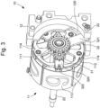
figures 1 et 2 représentent des vues éclatées en perspective d'un dispositif d'affichage d'un mouvement horloger selon exemple préféré de réalisation de l'invention ; - la
figure 3 représente une vue en perspective du dispositif de lafigure 1 . - On note que les figures ne sont pas nécessairement dessinées à l'échelle pour des raisons de clarté.
- L'invention concerne un dispositif d'affichage 10 d'un mouvement horloger comprenant un afficheur 11 destiné à être monté de façon mobile relativement à une structure 12 du mouvement horloger, telle qu'une platine ou un pont, et un mécanisme d'entraînement 20 destiné à recevoir l'énergie d'un organe moteur du mouvement afin d'entraîner l'afficheur 11 en déplacement. Le dispositif d'affichage 10 comporte en outre un mécanisme d'accouplement 30 configuré pour relier cinématiquement l'afficheur 11 avec le mécanisme d'entraînement 20.
- Comme le montrent les vues éclatées des
figures 1 à 3 , l'afficheur 11 comprend un organe d'indexation 110 imposant une orientation précise dudit afficheur 11 par rapport à la structure 12. L'afficheur 11 comporte également une roue menée 111 dont la rotation entraîne le déplacement de l'afficheur 11. La roue menée 111 est destinée à être entraînée en rotation par le mécanisme d'entraînement 20, et en particulier, par une roue menante 21 de ce dernier, par l'intermédiaire d'une roue de transmission 31 du mécanisme d'accouplement 30. - Le mécanisme d'accouplement 30 est avantageusement configuré de sorte que le centre de rotation de la roue de transmission 31 présente un degré de mobilité par rapport au roues menante 21 et menée 111.
- Cette caractéristique permet avantageusement de pouvoir ajuster la position de la roue de transmission 31 par rapport aux roues menante 21 et menée 111 de sorte à permettre une indexation correcte de l'élément d'affichage.
- Dans l'exemple de réalisation préféré de la présente invention représenté sur les
figures 1 à 3 , l'afficheur 11 comporte un rouleau formé par deux flasques 112 latéraux montés mobiles en rotation sur un arbre menant 22 et entre lesquels sont interposés des volets 113 mobiles en rotation respectivement selon des axes parallèles à celui des flasques 112. Un tel rouleau est par exemple conforme à celui décrit dans le brevetEP3627240 . - Comme visible sur les
figures 1 à 3 , la roue menée 111 est agencée sur l'arbre menant 22 de manière libre en rotation et est cinématiquement liée à un des flasques 112, de sorte que la rotation de la roue menée 111 entraîne la rotation du flasque 112, et donc du rouleau. En particulier, la roue menée 111 est fixée sans degré de liberté audit flasque 112. - L'organe d'indexation 110 coopère avec la périphérie d'un des flasque 112 afin d'indexer la position de l'afficheur 11. En particulier, dans l'exemple préféré de réalisation de l'invention, ledit flasque 112 comporte une pluralité de crans 114 radiaux correspondant chacun à une position de l'afficheur 11. L'organe d'indexation 110 comporte un doigt 115 configuré de sorte à prendre une position d'indexation dans laquelle il est engagé avec un cran 114 du flasque 112 et une position de retrait dans laquelle il est dégagé du cran 114. Le doigt 115 est entraîné entre les positions d'indexation et de retrait par un arbre de commande 116 sur lequel il est fixé, qui est déplacé selon une fréquence prédéterminée, par exemple une fois par jour si l'afficheur 11 est un afficheur de quantième.
- Alternativement, l'organe d'indexation 110 peut indexer l'afficheur 11 de manière passive, par exemple, par déformation élastique, à la manière d'un sautoir.
- La roue menante 21 est entraînée en rotation par l'arbre menant 22 auquel elle est fixée sans degré de liberté. Préférentiellement, la roue menante 21 est formée par une couronne comportant une denture interne reliée à une serge, comme le montre la
figure 1 . Ainsi, la roue menante 21 et la roue menée 111 sont coaxiales et leur axe de rotation est confondu. - Dans cette configuration, la roue de transmission 31 forme un satellite de la roue menée 111, qui forme une roue solaire.
- Tel qu'illustré sur les
figures 1 à 3 , le mécanisme d'accouplement 30 comporte un support 32 sur lequel est fixée la roue de transmission 31 de façon mobile en rotation. Le support 32 est avantageusement configuré pour occuper un état mobile en rotation autour de l'axe de rotation de la roue menante 21 et un état immobile dans lequel il est destiné à être maintenu en position par rapport à la structure 12, par un organe de blocage 33. - En particulier, le support 32 présente deux bras radiaux, dont un premier bras 320 porte la roue de transmission 31 et dont un second bras 321 est destiné à être maintenu par serrage dans une encoche 120 de la structure 12 par l'organe de blocage 33 lorsque le support 32 occupe l'état immobile. Un tel organe de blocage 33 peut avantageusement être une vis prévue pour être engagée dans la structure 12 selon une liaison hélicoïdale, comme illustré sur les figures. Ainsi, après avoir été orienté convenablement, c'est-à-dire de sorte que la roue de transmission 31 engrène avec les roues menante 21 et menée 111, le support 32 peut être serré contre la structure 12 par la vis.
- L'orientation du support 32 peut être réalisé par la manipulation d'un organe de réglage 322 du support 32, constitué, dans l'exemple préféré de réalisation de l'invention, par une extrémité libre du premier bras 320. Plus précisément, l'organe de réglage 322 du support 32 peut être réalisé par une encoche destinée recevoir une lame d'un outil, par exemple d'un tournevis.
- De manière plus générale, il est à noter que les modes de mise en oeuvre et de réalisation considérés ci-dessus ont été décrits à titre d'exemples non limitatifs, et que d'autres variantes sont par conséquent envisageables.
Claims (9)
- Dispositif d'affichage (10) d'un mouvement horloger caractérisé en ce qu'il comprend :- un afficheur (11) destiné à être monté mobile relativement à une structure (12) du mouvement horloger et doté d'un organe d'indexation (110) par rapport à ladite structure (12), et d'une roue menée (111) dont la rotation entraîne le déplacement de l'afficheur (11) ;- un mécanisme d'entraînement (20) comprenant une roue menante (21) destinée à entraîner en rotation la roue menée (111) ;- un mécanisme d'accouplement (30) comprenant une roue de transmission (31) engrenant avec la roue menante (21) et la roue menée (111), ledit mécanisme d'accouplement (30) étant configuré de sorte que le centre de rotation de la roue de transmission (31) présente un degré de mobilité par rapport au roues menante (21) et menée (111).
- Dispositif d'affichage (10) selon la revendication 1, dans lequel le mécanisme d'accouplement (30) comporte un support (32) sur lequel est fixée la roue de transmission (31) de façon mobile en rotation, le support (32) étant configuré pour occuper un état mobile en rotation autour de l'axe de rotation de la roue menante (21) et un état immobile dans lequel il est maintenu en position par un organe de blocage (33).
- Dispositif d'affichage (10) selon la revendication 2, dans lequel la roue de transmission (31) forme un satellite de la roue menée (111) et la roue menante (21) est formée par une couronne comportant une denture interne.
- Dispositif d'affichage (10) selon la revendication 3, dans lequel la roue menante (21) et la roue menée (111) sont agencées de façon coaxiale.
- Dispositif d'affichage (10) selon la revendication 2, dans lequel le support (32) présente deux bras radiaux (320, 321), dont un porte la roue de transmission (31) et dont l'autre est maintenu par serrage dans une encoche de la structure (12) du mouvement horloger par l'organe de blocage (33) lorsque le support (32) occupe l'état immobile.
- Dispositif d'affichage (10) selon la revendication 5, dans lequel un des bras (320) comprend un organe de réglage (322), dont la sollicitation permet de déplacer le support (32) lorsqu'il occupe l'état mobile.
- Dispositif d'affichage (10) selon la revendication 6, dans lequel l'extrémité libre du bras (320) portant le mobile de transmission présente l'organe de réglage (322), ce dernier étant formé par une encoche.
- Dispositif d'affichage (10) selon la revendication 2, dans lequel l'afficheur (11) comporte un rouleau mobile en rotation et formé par deux flasques (112) latéraux entre lesquels sont interposés des volets (113) mobiles en rotation respectivement selon des axes parallèles à celui du rouleau, un des flasques (112) étant cinématiquement lié à la roue menée (111), l'axe de rotation des roues menante (21) et menée (111) étant confondu avec celui du rouleau.
- Mouvement horloger comprenant une structure (12) et un dispositif d'affichage (10) selon l'une des revendications 1 à 8.
Priority Applications (5)
| Application Number | Priority Date | Filing Date | Title |
|---|---|---|---|
| EP24202285.3A EP4564108A1 (fr) | 2023-11-23 | 2023-11-23 | Dispositif d'affichage comprenant un mécanisme d'accouplement avec un mouvement horloger |
| EP23211817.4A EP4560411A1 (fr) | 2023-11-23 | 2023-11-23 | Dispositif d'affichage comprenant un mécanisme d'accouplement avec un mouvement horloger |
| US18/904,714 US20250172911A1 (en) | 2023-11-23 | 2024-10-02 | Display device comprising a mechanism for coupling to a watch movement |
| JP2024179768A JP7815588B2 (ja) | 2023-11-23 | 2024-10-15 | 腕時計ムーブメントのための表示装置、及び同表示装置を含む腕時計ムーブメント |
| CN202411633984.7A CN120029025A (zh) | 2023-11-23 | 2024-11-15 | 包括用于联接到手表机芯的联接机构的显示装置 |
Applications Claiming Priority (1)
| Application Number | Priority Date | Filing Date | Title |
|---|---|---|---|
| EP23211817.4A EP4560411A1 (fr) | 2023-11-23 | 2023-11-23 | Dispositif d'affichage comprenant un mécanisme d'accouplement avec un mouvement horloger |
Related Child Applications (2)
| Application Number | Title | Priority Date | Filing Date |
|---|---|---|---|
| EP24202285.3A Division EP4564108A1 (fr) | 2023-11-23 | 2023-11-23 | Dispositif d'affichage comprenant un mécanisme d'accouplement avec un mouvement horloger |
| EP24202285.3A Division-Into EP4564108A1 (fr) | 2023-11-23 | 2023-11-23 | Dispositif d'affichage comprenant un mécanisme d'accouplement avec un mouvement horloger |
Publications (1)
| Publication Number | Publication Date |
|---|---|
| EP4560411A1 true EP4560411A1 (fr) | 2025-05-28 |
Family
ID=88965737
Family Applications (2)
| Application Number | Title | Priority Date | Filing Date |
|---|---|---|---|
| EP24202285.3A Pending EP4564108A1 (fr) | 2023-11-23 | 2023-11-23 | Dispositif d'affichage comprenant un mécanisme d'accouplement avec un mouvement horloger |
| EP23211817.4A Pending EP4560411A1 (fr) | 2023-11-23 | 2023-11-23 | Dispositif d'affichage comprenant un mécanisme d'accouplement avec un mouvement horloger |
Family Applications Before (1)
| Application Number | Title | Priority Date | Filing Date |
|---|---|---|---|
| EP24202285.3A Pending EP4564108A1 (fr) | 2023-11-23 | 2023-11-23 | Dispositif d'affichage comprenant un mécanisme d'accouplement avec un mouvement horloger |
Country Status (4)
| Country | Link |
|---|---|
| US (1) | US20250172911A1 (fr) |
| EP (2) | EP4564108A1 (fr) |
| JP (1) | JP7815588B2 (fr) |
| CN (1) | CN120029025A (fr) |
Citations (2)
| Publication number | Priority date | Publication date | Assignee | Title |
|---|---|---|---|---|
| EP3267266A1 (fr) * | 2016-07-05 | 2018-01-10 | Montres Breguet S.A. | Mécanisme d'affichage à rouleau pour montre |
| EP3584642B1 (fr) * | 2018-06-18 | 2021-01-13 | Montres Breguet S.A. | Mecanisme de reglage pour mecanisme d'affichage d'horlogerie a rouleau |
-
2023
- 2023-11-23 EP EP24202285.3A patent/EP4564108A1/fr active Pending
- 2023-11-23 EP EP23211817.4A patent/EP4560411A1/fr active Pending
-
2024
- 2024-10-02 US US18/904,714 patent/US20250172911A1/en active Pending
- 2024-10-15 JP JP2024179768A patent/JP7815588B2/ja active Active
- 2024-11-15 CN CN202411633984.7A patent/CN120029025A/zh active Pending
Patent Citations (3)
| Publication number | Priority date | Publication date | Assignee | Title |
|---|---|---|---|---|
| EP3267266A1 (fr) * | 2016-07-05 | 2018-01-10 | Montres Breguet S.A. | Mécanisme d'affichage à rouleau pour montre |
| EP3627240A1 (fr) | 2016-07-05 | 2020-03-25 | Montres Breguet S.A. | Mécanisme d'affichage à rouleau pour montre |
| EP3584642B1 (fr) * | 2018-06-18 | 2021-01-13 | Montres Breguet S.A. | Mecanisme de reglage pour mecanisme d'affichage d'horlogerie a rouleau |
Also Published As
| Publication number | Publication date |
|---|---|
| JP7815588B2 (ja) | 2026-02-18 |
| US20250172911A1 (en) | 2025-05-29 |
| EP4564108A1 (fr) | 2025-06-04 |
| CN120029025A (zh) | 2025-05-23 |
| JP2025085067A (ja) | 2025-06-04 |
Similar Documents
| Publication | Publication Date | Title |
|---|---|---|
| EP2945026B1 (fr) | Mécanisme de correction rapide d'horlogerie | |
| EP4560411A1 (fr) | Dispositif d'affichage comprenant un mécanisme d'accouplement avec un mouvement horloger | |
| CH704250B1 (fr) | Mécanisme de transmission de mouvements axiaux et rotatifs entre deux axes décalés et pièce d'horlogerie comportant un tel mécanisme. | |
| EP4113221A1 (fr) | Montre comprenant un cadran comportant une partie fixe et une partie mobile | |
| CH721318A2 (fr) | Dispositif d'affichage comprenant un mécanisme d'accouplement avec un mouvement horloger | |
| CH707971A1 (fr) | Pièce d'horlogerie comprenant un dispositif d'affichage de quantième. | |
| EP3246763B1 (fr) | Mécanisme de correction rapide pour pièce d'horlogerie | |
| CH691200A5 (fr) | Dispositif de mise à l'heure pour pièce d'horlogerie. | |
| EP0029204B1 (fr) | Mécanisme de positionnement d'une roue de centre | |
| EP2689299B1 (fr) | Support pour organe d'affichage de mouvement horloger | |
| CH714602B1 (fr) | Mécanisme d'une montre pourvue d'une tige de remontoir. | |
| CH720210B1 (fr) | Mouvement horloger comprenant un mécanisme de commande de quantième | |
| CH704334A1 (fr) | Pièce d'horlogerie à remontage automatique. | |
| CH712477A2 (fr) | Dispositif de correction rapide d'une indication fournie par un mécanisme d'affichage pour pièce d'horlogerie. | |
| EP2010972A2 (fr) | Piece d'horlogerie comportant un mecanisme de mise a l'heure commande par une lunette tournante | |
| EP4685576A1 (fr) | Mécanisme de liaison cinématique pour mouvement horloger | |
| EP4369112A1 (fr) | Mécanisme d'affichage des années bissextiles d'un mouvement horloger à affichage de quantième perpétuel | |
| CH722011A2 (fr) | Mécanisme de liaison cinématique pour mouvement horloger | |
| EP4354230A1 (fr) | Presse pour le chassage d'une lunette ou d'une glace de montre | |
| CH717215A2 (fr) | Mécanisme de guidage, mécanisme d'affichage, mouvement et pièce d'horlogerie. | |
| EP1925996A1 (fr) | Dispositif de correction d'un mécanisme d'affichage pour pièce d'horlogerie | |
| EP4546056A1 (fr) | Mouvement horloger comprenant un mécanisme de réglage de la position d afficheurs | |
| EP4312083A1 (fr) | Dispositif d'embrayage-débrayage pour piece d'horlogerie | |
| CH721218A2 (fr) | Mouvement horloger comprenant un mécanisme de réglage de la position d'afficheurs | |
| EP2000864A1 (fr) | Dispositif de correction d'un mécanisme d'affichage pour pièce d'horlogerie |
Legal Events
| Date | Code | Title | Description |
|---|---|---|---|
| PUAI | Public reference made under article 153(3) epc to a published international application that has entered the european phase |
Free format text: ORIGINAL CODE: 0009012 |
|
| STAA | Information on the status of an ep patent application or granted ep patent |
Free format text: STATUS: THE APPLICATION HAS BEEN PUBLISHED |
|
| AK | Designated contracting states |
Kind code of ref document: A1 Designated state(s): AL AT BE BG CH CY CZ DE DK EE ES FI FR GB GR HR HU IE IS IT LI LT LU LV MC ME MK MT NL NO PL PT RO RS SE SI SK SM TR |
|
| P01 | Opt-out of the competence of the unified patent court (upc) registered |
Free format text: CASE NUMBER: APP_29142/2025 Effective date: 20250618 |
|
| STAA | Information on the status of an ep patent application or granted ep patent |
Free format text: STATUS: REQUEST FOR EXAMINATION WAS MADE |
|
| 17P | Request for examination filed |
Effective date: 20251114 |