EP4560430A1 - Dispositif électronique pouvant rouler - Google Patents
Dispositif électronique pouvant rouler Download PDFInfo
- Publication number
- EP4560430A1 EP4560430A1 EP23875145.7A EP23875145A EP4560430A1 EP 4560430 A1 EP4560430 A1 EP 4560430A1 EP 23875145 A EP23875145 A EP 23875145A EP 4560430 A1 EP4560430 A1 EP 4560430A1
- Authority
- EP
- European Patent Office
- Prior art keywords
- housing
- electronic device
- support member
- display
- plate
- Prior art date
- Legal status (The legal status is an assumption and is not a legal conclusion. Google has not performed a legal analysis and makes no representation as to the accuracy of the status listed.)
- Pending
Links
Images


Classifications
-
- H—ELECTRICITY
- H04—ELECTRIC COMMUNICATION TECHNIQUE
- H04M—TELEPHONIC COMMUNICATION
- H04M1/00—Substation equipment, e.g. for use by subscribers
- H04M1/02—Constructional features of telephone sets
- H04M1/0202—Portable telephone sets, e.g. cordless phones, mobile phones or bar type handsets
- H04M1/0206—Portable telephones comprising a plurality of mechanically joined movable body parts, e.g. hinged housings
- H04M1/0208—Portable telephones comprising a plurality of mechanically joined movable body parts, e.g. hinged housings characterized by the relative motions of the body parts
- H04M1/0235—Slidable or telescopic telephones, i.e. with a relative translation movement of the body parts; Telephones using a combination of translation and other relative motions of the body parts
- H04M1/0237—Sliding mechanism with one degree of freedom
-
- G—PHYSICS
- G06—COMPUTING OR CALCULATING; COUNTING
- G06F—ELECTRIC DIGITAL DATA PROCESSING
- G06F1/00—Details not covered by groups G06F3/00 - G06F13/00 and G06F21/00
- G06F1/16—Constructional details or arrangements
- G06F1/1613—Constructional details or arrangements for portable computers
- G06F1/1615—Constructional details or arrangements for portable computers with several enclosures having relative motions, each enclosure supporting at least one I/O or computing function
- G06F1/1624—Constructional details or arrangements for portable computers with several enclosures having relative motions, each enclosure supporting at least one I/O or computing function with sliding enclosures, e.g. sliding keyboard or display
-
- G—PHYSICS
- G06—COMPUTING OR CALCULATING; COUNTING
- G06F—ELECTRIC DIGITAL DATA PROCESSING
- G06F1/00—Details not covered by groups G06F3/00 - G06F13/00 and G06F21/00
- G06F1/16—Constructional details or arrangements
- G06F1/1613—Constructional details or arrangements for portable computers
- G06F1/1633—Constructional details or arrangements of portable computers not specific to the type of enclosures covered by groups G06F1/1615 - G06F1/1626
- G06F1/1635—Details related to the integration of battery packs and other power supplies such as fuel cells or integrated AC adapter
-
- G—PHYSICS
- G06—COMPUTING OR CALCULATING; COUNTING
- G06F—ELECTRIC DIGITAL DATA PROCESSING
- G06F1/00—Details not covered by groups G06F3/00 - G06F13/00 and G06F21/00
- G06F1/16—Constructional details or arrangements
- G06F1/1613—Constructional details or arrangements for portable computers
- G06F1/1633—Constructional details or arrangements of portable computers not specific to the type of enclosures covered by groups G06F1/1615 - G06F1/1626
- G06F1/1637—Details related to the display arrangement, including those related to the mounting of the display in the housing
- G06F1/1652—Details related to the display arrangement, including those related to the mounting of the display in the housing the display being flexible, e.g. mimicking a sheet of paper, or rollable
-
- G—PHYSICS
- G06—COMPUTING OR CALCULATING; COUNTING
- G06F—ELECTRIC DIGITAL DATA PROCESSING
- G06F1/00—Details not covered by groups G06F3/00 - G06F13/00 and G06F21/00
- G06F1/16—Constructional details or arrangements
- G06F1/1613—Constructional details or arrangements for portable computers
- G06F1/1633—Constructional details or arrangements of portable computers not specific to the type of enclosures covered by groups G06F1/1615 - G06F1/1626
- G06F1/1675—Miscellaneous details related to the relative movement between the different enclosures or enclosure parts
- G06F1/1681—Details related solely to hinges
-
- G—PHYSICS
- G06—COMPUTING OR CALCULATING; COUNTING
- G06F—ELECTRIC DIGITAL DATA PROCESSING
- G06F1/00—Details not covered by groups G06F3/00 - G06F13/00 and G06F21/00
- G06F1/16—Constructional details or arrangements
- G06F1/18—Packaging or power distribution
- G06F1/183—Internal mounting support structures, e.g. for supporting printed circuit boards
-
- G—PHYSICS
- G06—COMPUTING OR CALCULATING; COUNTING
- G06F—ELECTRIC DIGITAL DATA PROCESSING
- G06F1/00—Details not covered by groups G06F3/00 - G06F13/00 and G06F21/00
- G06F1/26—Power supply means, e.g. regulation thereof
- G06F1/263—Arrangements for using multiple switchable power supplies, e.g. battery and AC
-
- G—PHYSICS
- G09—EDUCATION; CRYPTOGRAPHY; DISPLAY; ADVERTISING; SEALS
- G09F—DISPLAYING; ADVERTISING; SIGNS; LABELS OR NAME-PLATES; SEALS
- G09F9/00—Indicating arrangements for variable information in which the information is built-up on a support by selection or combination of individual elements
- G09F9/30—Indicating arrangements for variable information in which the information is built-up on a support by selection or combination of individual elements in which the desired character or characters are formed by combining individual elements
- G09F9/301—Indicating arrangements for variable information in which the information is built-up on a support by selection or combination of individual elements in which the desired character or characters are formed by combining individual elements flexible foldable or roll-able electronic displays, e.g. thin LCD, OLED
-
- H—ELECTRICITY
- H04—ELECTRIC COMMUNICATION TECHNIQUE
- H04M—TELEPHONIC COMMUNICATION
- H04M1/00—Substation equipment, e.g. for use by subscribers
- H04M1/02—Constructional features of telephone sets
- H04M1/0202—Portable telephone sets, e.g. cordless phones, mobile phones or bar type handsets
- H04M1/026—Details of the structure or mounting of specific components
- H04M1/0262—Details of the structure or mounting of specific components for a battery compartment
-
- H—ELECTRICITY
- H04—ELECTRIC COMMUNICATION TECHNIQUE
- H04M—TELEPHONIC COMMUNICATION
- H04M1/00—Substation equipment, e.g. for use by subscribers
- H04M1/02—Constructional features of telephone sets
- H04M1/0202—Portable telephone sets, e.g. cordless phones, mobile phones or bar type handsets
- H04M1/026—Details of the structure or mounting of specific components
- H04M1/0266—Details of the structure or mounting of specific components for a display module assembly
- H04M1/0268—Details of the structure or mounting of specific components for a display module assembly including a flexible display panel
Definitions
- An embodiment of the disclosure relates to a rollable electronic device.
- the electronic devices may output information stored therein as sound or an image.
- a single electronic device such as a mobile communication terminal, may be now equipped with various functions.
- entertainment functions such as gaming, multimedia functions such as music/video playback, communication and security functions for mobile banking or the like, as well as schedule management and electronic wallet functions, are being integrated into a single electronic device.
- These electronic devices are being miniaturized to be conveniently carried by users. With the recent emphasis on miniaturization, slimness, and portability of portable electronic devices such as smartphones, research is continuously being conducted to aesthetically enhance the design of the appearance of electronic devices.
- an electronic device may include a first housing, a second housing configured to slide relative to the first housing, a display including a first display area disposed on the first housing and a second display area extending from the first display area, the display being configured such that at least a portion of the second display area is slid based on sliding of the second housing, a first battery disposed in the first housing, a second battery disposed in the second housing and configured to slide based on the sliding of the second housing, a plate disposed in the second housing and configured to provide a seating space for the second battery based on the sliding of the second housing, and a support member having one end connected to the first housing and the other end connected to the plate, the support member being configured to move based on the sliding of the second housing.
- An electronic device may include a first housing, a second housing configured to slide relative to the first housing, a display including a first display area disposed on the first housing and a second display area extending from the first display area, the display being configured such that at least a portion of the second display area is slid based on sliding of the second housing, a first component disposed in the first housing; a second component disposed in the second housing and configured to slide based on the sliding of the second housing, a plate disposed in the second housing and configured to provide a seating space for the second component based on the sliding of the second housing, and a support member having one end connected to the first housing and the other end connected to the plate, the support member being configured to move based on the sliding of the second housing.
- FIG. 1 is a block diagram illustrating an electronic device 101 in a network environment 100 according to various embodiments.
- the electronic device 101 in the network environment 100 may communicate with an electronic device 102 via a first network 198 (e.g., a short-range wireless communication network), or at least one of an electronic device 104 or a server 108 via a second network 199 (e.g., a long-range wireless communication network).
- a first network 198 e.g., a short-range wireless communication network
- a second network 199 e.g., a long-range wireless communication network
- the electronic device 101 may communicate with the electronic device 104 via the server 108.
- the electronic device 101 may include a processor 120, memory 130, an input module 150, a sound output module 155, a display module 160, an audio module 170, a sensor module 176, an interface 177, a connecting terminal 178, a haptic module 179, a camera module 180, a power management module 188, a battery 189, a communication module 190, a subscriber identification module (SIM) 196, or an antenna module 197.
- at least one of the components e.g., the connecting terminal 178) may be omitted from the electronic device 101, or one or more other components may be added in the electronic device 101.
- some of the components e.g., the sensor module 176, the camera module 180, or the antenna module 197) may be implemented as a single component (e.g., the display module 160).
- the processor 120 may include a main processor 121 (e.g., a central processing unit (CPU) or an application processor (AP)), or an auxiliary processor 123 (e.g., a graphics processing unit (GPU), a neural processing unit (NPU), an image signal processor (ISP), a sensor hub processor, or a communication processor (CP)) that is operable independently from, or in conjunction with, the main processor 121.
- a main processor 121 e.g., a central processing unit (CPU) or an application processor (AP)
- auxiliary processor 123 e.g., a graphics processing unit (GPU), a neural processing unit (NPU), an image signal processor (ISP), a sensor hub processor, or a communication processor (CP)
- the main processor 121 may be adapted to consume less power than the main processor 121, or to be specific to a specified function.
- the auxiliary processor 123 may be implemented as separate from, or as part of the main processor 121.
- the auxiliary processor 123 may control at least some of functions or states related to at least one component (e.g., the display module 160, the sensor module 176, or the communication module 190) among the components of the electronic device 101, instead of the main processor 121 while the main processor 121 is in an inactive (e.g., sleep) state, or together with the main processor 121 while the main processor 121 is in an active state (e.g., executing an application).
- the auxiliary processor 123 e.g., an image signal processor or a communication processor
- the auxiliary processor 123 may include a hardware structure specified for artificial intelligence model processing.
- An artificial intelligence model may be generated by machine learning. Such learning may be performed, e.g., by the electronic device 101 where the artificial intelligence is performed or via a separate server (e.g., the server 108). Learning algorithms may include, but are not limited to, e.g., supervised learning, unsupervised learning, semi-supervised learning, or reinforcement learning.
- the artificial intelligence model may include a plurality of artificial neural network layers.
- the artificial neural network may be a deep neural network (DNN), a convolutional neural network (CNN), a recurrent neural network (RNN), a restricted Boltzmann machine (RBM), a deep belief network (DBN), a bidirectional recurrent deep neural network (BRDNN), deep Q-network or a combination of two or more thereof but is not limited thereto.
- the artificial intelligence model may, additionally or alternatively, include a software structure other than the hardware structure.
- the memory 130 may store various data used by at least one component (e.g., the processor 120 or the sensor module 176) of the electronic device 101.
- the various data may include, for example, software (e.g., the program 140) and input data or output data for a command related thereto.
- the memory 130 may include the volatile memory 132 or the non-volatile memory 134.
- the program 140 may be stored in the memory 130 as software, and may include, for example, an operating system (OS) 142, middleware 144, or an application 146.
- OS operating system
- middleware middleware
- application application
- the input module 150 may receive a command or data to be used by another component (e.g., the processor 120) of the electronic device 101, from the outside (e.g., a user) of the electronic device 101.
- the input module 150 may include, for example, a microphone, a mouse, a keyboard, a key (e.g., a button), or a digital pen (e.g., a stylus pen).
- the sound output module 155 may output sound signals to the outside of the electronic device 101.
- the sound output module 155 may include, for example, a speaker or a receiver.
- the speaker may be used for general purposes, such as playing multimedia or playing record.
- the receiver may be used for receiving incoming calls. According to an embodiment, the receiver may be implemented as separate from, or as part of the speaker.
- the display module 160 may visually provide information to the outside (e.g., a user) of the electronic device 101.
- the display module 160 may include, for example, a display, a hologram device, or a projector and control circuitry to control a corresponding one of the display, hologram device, and projector.
- the display module 160 may include a touch sensor adapted to detect a touch, or a pressure sensor adapted to measure the intensity of force incurred by the touch.
- the audio module 170 may convert a sound into an electrical signal and vice versa. According to an embodiment, the audio module 170 may obtain the sound via the input module 150, or output the sound via the sound output module 155 or a headphone of an external electronic device (e.g., an electronic device 102) directly (e.g., wiredly) or wirelessly coupled with the electronic device 101.
- an external electronic device e.g., an electronic device 102
- directly e.g., wiredly
- wirelessly e.g., wirelessly
- the sensor module 176 may detect an operational state (e.g., power or temperature) of the electronic device 101 or an environmental state (e.g., a state of a user) external to the electronic device 101, and then generate an electrical signal or data value corresponding to the detected state.
- the sensor module 176 may include, for example, a gesture sensor, a gyro sensor, an atmospheric pressure sensor, a magnetic sensor, an acceleration sensor, a grip sensor, a proximity sensor, a color sensor, an infrared (IR) sensor, a biometric sensor, a temperature sensor, a humidity sensor, or an illuminance sensor.
- the interface 177 may support one or more specified protocols to be used for the electronic device 101 to be coupled with the external electronic device (e.g., the electronic device 102) directly (e.g., wiredly) or wirelessly.
- the interface 177 may include, for example, a high definition multimedia interface (HDMI), a universal serial bus (USB) interface, a secure digital (SD) card interface, or an audio interface.
- HDMI high definition multimedia interface
- USB universal serial bus
- SD secure digital
- a connecting terminal 178 may include a connector via which the electronic device 101 may be physically connected with the external electronic device (e.g., the electronic device 102).
- the connecting terminal 178 may include, for example, a HDMI connector, a USB connector, a SD card connector, or an audio connector (e.g., a headphone connector).
- the haptic module 179 may convert an electrical signal into a mechanical stimulus (e.g., a vibration or a movement) or electrical stimulus which may be recognized by a user via his tactile sensation or kinesthetic sensation.
- the haptic module 179 may include, for example, a motor, a piezoelectric element, or an electric stimulator.
- the camera module 180 may capture a still image or moving images.
- the camera module 180 may include one or more lenses, image sensors, image signal processors, or flashes.
- the power management module 188 may manage power supplied to the electronic device 101.
- the power management module 188 may be implemented as at least part of, for example, a power management integrated circuit (PMIC).
- PMIC power management integrated circuit
- the battery 189 may supply power to at least one component of the electronic device 101.
- the battery 189 may include, for example, a primary cell which is not rechargeable, a secondary cell which is rechargeable, or a fuel cell.
- the communication module 190 may support establishing a direct (e.g., wired) communication channel or a wireless communication channel between the electronic device 101 and the external electronic device (e.g., the electronic device 102, the electronic device 104, or the server 108) and performing communication via the established communication channel.
- the communication module 190 may include one or more communication processors that are operable independently from the processor 120 (e.g., the application processor (AP)) and supports a direct (e.g., wired) communication or a wireless communication.
- AP application processor
- the communication module 190 may include a wireless communication module 192 (e.g., a cellular communication module, a short-range wireless communication module, or a global navigation satellite system (GNSS) communication module) or a wired communication module 194 (e.g., a local area network (LAN) communication module or a power line communication (PLC) module).
- a wireless communication module 192 e.g., a cellular communication module, a short-range wireless communication module, or a global navigation satellite system (GNSS) communication module
- GNSS global navigation satellite system
- wired communication module 194 e.g., a local area network (LAN) communication module or a power line communication (PLC) module.
- LAN local area network
- PLC power line communication
- the wireless communication module 192 may support a 5G network, after a 4G network, and next-generation communication technology, e.g., new radio (NR) access technology.
- the NR access technology may support enhanced mobile broadband (eMBB), massive machine type communications (mMTC), or ultra-reliable and low-latency communications (URLLC).
- eMBB enhanced mobile broadband
- mMTC massive machine type communications
- URLLC ultra-reliable and low-latency communications
- the wireless communication module 192 may support a high-frequency band (e.g., the mmWave band) to achieve, e.g., a high data transmission rate.
- the wireless communication module 192 may support various technologies for securing performance on a high-frequency band, such as, e.g., beamforming, massive multiple-input and multiple-output (massive MIMO), full dimensional MIMO (FD-MIMO), array antenna, analog beam-forming, or large scale antenna.
- the wireless communication module 192 may support various requirements specified in the electronic device 101, an external electronic device (e.g., the electronic device 104), or a network system (e.g., the second network 199).
- the antenna module 197 may transmit or receive a signal or power to or from the outside (e.g., the external electronic device) of the electronic device 101.
- the antenna module 197 may include an antenna including a radiating element composed of a conductive material or a conductive pattern formed in or on a substrate (e.g., a printed circuit board (PCB)).
- the antenna module 197 may include a plurality of antennas (e.g., array antennas). In such a case, at least one antenna appropriate for a communication scheme used in the communication network, such as the first network 198 or the second network 199, may be selected, for example, by the communication module 190 (e.g., the wireless communication module 192) from the plurality of antennas.
- the signal or the power may then be transmitted or received between the communication module 190 and the external electronic device via the selected at least one antenna.
- another component e.g., a radio frequency integrated circuit (RFIC)
- RFIC radio frequency integrated circuit
- the antenna module 197 may form a mmWave antenna module.
- the mmWave antenna module may include a printed circuit board, a RFIC disposed on a first surface (e.g., the bottom surface) of the printed circuit board, or adjacent to the first surface and capable of supporting a designated high-frequency band (e.g., the mmWave band), and a plurality of antennas (e.g., array antennas) disposed on a second surface (e.g., the top or a side surface) of the printed circuit board, or adjacent to the second surface and capable of transmitting or receiving signals of the designated high-frequency band.
- a RFIC disposed on a first surface (e.g., the bottom surface) of the printed circuit board, or adjacent to the first surface and capable of supporting a designated high-frequency band (e.g., the mmWave band)
- a plurality of antennas e.g., array antennas
- At least some of the above-described components may be coupled mutually and communicate signals (e.g., commands or data) therebetween via an inter-peripheral communication scheme (e.g., a bus, general purpose input and output (GPIO), serial peripheral interface (SPI), or mobile industry processor interface (MIPI)).
- an inter-peripheral communication scheme e.g., a bus, general purpose input and output (GPIO), serial peripheral interface (SPI), or mobile industry processor interface (MIPI)
- commands or data may be transmitted or received between the electronic device 101 and the external electronic device 104 via the server 108 coupled with the second network 199.
- Each of the electronic devices 102 or 104 may be a device of a same type as, or a different type, from the electronic device 101.
- all or some of operations to be executed at the electronic device 101 may be executed at one or more of the external electronic devices 102, 104, or 108. For example, if the electronic device 101 should perform a function or a service automatically, or in response to a request from a user or another device, the electronic device 101, instead of, or in addition to, executing the function or the service, may request the one or more external electronic devices to perform at least part of the function or the service.
- the one or more external electronic devices receiving the request may perform the at least part of the function or the service requested, or an additional function or an additional service related to the request, and transfer an outcome of the performing to the electronic device 101.
- the electronic device 101 may provide the outcome, with or without further processing of the outcome, as at least part of a reply to the request.
- a cloud computing, distributed computing, mobile edge computing (MEC), or client-server computing technology may be used, for example.
- the electronic device 101 may provide ultra low-latency services using, e.g., distributed computing or mobile edge computing.
- the external electronic device 104 may include an intemet-of-things (IoT) device.
- the server 108 may be an intelligent server using machine learning and/or a neural network.
- the external electronic device 104 or the server 108 may be included in the second network 199.
- the electronic device 101 may be applied to intelligent services (e.g., smart home, smart city, smart car, or healthcare) based on 5G communication technology or IoT-related technology.
- the electronic device may be one of various types of electronic devices.
- the electronic devices may include, for example, a portable communication device (e.g., a smartphone), a computer device, a portable multimedia device, a portable medical device, a camera, a wearable device, or a home appliance.
- a portable communication device e.g., a smartphone
- a computer device e.g
- each of such phrases as “A or B,” “at least one of A and B,” “at least one of A or B,” “A, B, or C,” “at least one of A, B, and C,” and “at least one of A, B, or C,” may include any one of, or all possible combinations of the items enumerated together in a corresponding one of the phrases.
- such terms as “1st” and “2nd,” or “first” and “second” may be used to simply distinguish a corresponding component from another, and does not limit the components in other aspect (e.g., importance or order).
- an element e.g., a first element
- the element may be coupled with the other element directly (e.g., wiredly), wirelessly, or via a third element.
- module may include a unit implemented in hardware, software, or firmware, and may interchangeably be used with other terms, for example, “logic,” “logic block,” “part,” or “circuitry”.
- a module may be a single integral component, or a minimum unit or part thereof, adapted to perform one or more functions.
- the module may be implemented in a form of an application-specific integrated circuit (ASIC).
- ASIC application-specific integrated circuit
- An embodiment as set forth herein may be implemented as software (e.g., the program) including one or more instructions that are stored in a storage medium (e.g., intemal memory or external memory) that is readable by a machine (e.g., the electronic device).
- a processor e.g., the processor
- the machine e.g., the electronic device
- the one or more instructions may include a code generated by a complier or a code executable by an interpreter.
- the machine-readable storage medium may be provided in the form of a non-transitory storage medium.
- non-transitory simply means that the storage medium is a tangible device, and does not include a signal (e.g., an electromagnetic wave), but this term does not differentiate between where data is semi-permanently stored in the storage medium and where the data is temporarily stored in the storage medium.
- a method according to an embodiment of the disclosure may be included and provided in a computer program product.
- the computer program product may be traded as a product between a seller and a buyer.
- the computer program product may be distributed in the form of a machine-readable storage medium (e.g., compact disc read only memory (CD-ROM)), or be distributed (e.g., downloaded or uploaded) online via an application store (e.g., PlayStore TM ), or between two user devices (e.g., smart phones) directly. If distributed online, at least part of the computer program product may be temporarily generated or at least temporarily stored in the machine-readable storage medium, such as memory of the manufacturer's server, a server of the application store, or a relay server.
- CD-ROM compact disc read only memory
- an application store e.g., PlayStore TM
- two user devices e.g., smart phones
- each component e.g., a module or a program of the above-described components may include a single entity or multiple entities, and some of the multiple entities may be separately disposed in different components. According to various embodiments, one or more of the above-described components may be omitted, or one or more other components may be added. Alternatively or additionally, a plurality of components (e.g., modules or programs) may be integrated into a single component. In such a case, according to various embodiments, the integrated component may still perform one or more functions of each of the plurality of components in the same or similar manner as they are performed by a corresponding one of the plurality of components before the integration.
- operations performed by the module, the program, or another component may be carried out sequentially, in parallel, repeatedly, or heuristically, or one or more of the operations may be executed in a different order or omitted, or one or more other operations may be added.
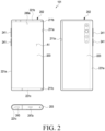
- the display 203 (e.g., the second display area A2) may be accommodated inside the second housing 202 (e.g., a slide-in operation) or visually exposed outside the second housing 202 (e.g., a slide-out operation).
- a motor, a speaker, a SIM socket, and/or a sub-circuit board electrically connected to the main circuit board may be arranged within the first housing 201.
- the main circuit board on which electrical components such as an application processor (AP) and a communication processor (CP) are mounted may be arranged within the second housing 202.
- the first housing 201 may include first side walls 211a, 211b, and 211c for surrounding at least a portion of the display 203 and/or a display support member (e.g., the display support member 213 in FIG. 4 ).
- the first side walls 211a, 211b, and 211c may extend from a first plate (e.g., the first plate 211 in FIG. 4 ).
- the second housing 202 may include second side walls 221a, 221b, and 221c for surrounding at least a portion of the first housing 201.
- the second side walls 221a, 221b, and 221c may extend from the second plate (e.g., the second plate 221 in FIG. 4 ) and/or the cover member (e.g., the cover member 222 in FIG. 4 ).
- the second side walls 221a, 221b, and 221c may include a (2-2) th side wall 221b, a (2-3) th side wall 221c opposite to the (2-2) th side wall 221b, and a (2-1) th side wall 221a extending from the (2-2) th side wall 221b to the (2-3) th side wall 221c.
- the (2-1) th side wall 221a may be substantially perpendicular to the (2-2) th side wall 221b and/or the (2-3) th side wall 221c.
- the cover member 222 and/or the (2-1) th side wall 221a may cover at least a portion of the display 203.
- at least a portion of the display 203 e.g., the second display area A2
- the cover member 222 and/or the (2-1) th side wall 221a may cover a portion of the display 203 accommodated inside the second housing 202.
- the electronic device 101 may include the display 203.
- the display 203 may be interpreted as a flexible display or a rollable display.
- at least a portion of the display 203 (e.g., the second display area A2) may slide based on the sliding of the first housing 201.
- the display 203 may be arranged adjacent to or include a touch-sensing circuit, a pressure sensor capable of measuring touch intensity (pressure), and/or a digitizer configured to detect a magnetic field-type stylus pen.
- the configuration of the display 203 in FIGS. 2 and/or 3 may be wholly or partially the same as that of the display module 160 in FIG. 1 .
- the display 203 may include a first display area A1 and a second display area A2.
- the first display area A1 may always be visible from the exterior.
- the first display area A1 may be interpreted as an area that cannot be located inside the second housing 202.
- the first display area A1 may be seated on a portion of the first housing 201 (e.g., the first plate 211).
- the second display area A2 may extend from the first display area A1 and may be inserted or accommodated inside the second housing 202 or visually exposed outside the second housing 202, depending on the sliding of the first housing 201.
- the electronic device 101 may include one or more key input devices 241, connector holes 243, audio modules 247a and 247b, or camera modules 249a and 249b. Although not illustrated, the electronic device 101 may further include an indicator (e.g., an LED device) or various sensor modules.
- an indicator e.g., an LED device
- the configurations of the audio modules 247a and 247b and the camera modules 249a and 249b of FIGS. 2 and 3 may be wholly or partially the same as those of the audio module 170 and the camera module 180 of FIG. 1 .
- the key input device 241 may be located in an area of the second housing 202. Depending on the external appearance and use state, the electronic device 101 may be designed such that the illustrated key input devices 241 are omitted or one or more additional key input devices are included. According to an embodiment, the electronic device 101 may include key input devices (not illustrated), such as a home key button or touch pads arranged around the home key button. According to an embodiment (not illustrated), at least some of the key input devices 241 may be disposed on the second housing 202.
- the key input devices 241 may be used as a driving structure to provide the slide-in and slide-out operation of the display 203 automatically or semi-automatically.
- the display 203 may automatically slide in or slide out (automatic operation).
- the remaining section may be fully slid out by the force of an elastic member (not illustrated) and/or a driving mechanism (not illustrated) mounted within the electronic device 101 (semi-automatic operation).
- the state of the electronic device 101 may change from the closed state (e.g., FIG. 2 ) to the opened state (e.g., FIG. 3 ) through the slide-out operation.
- the slide-in operation of the electronic device 101 may also be performed to correspond to the slide-out operation.
- the connector hole 243 may be omitted in some embodiments and may accommodate a connector (e.g., a USB connector) for transmitting/receiving power and/or data to/from an external electronic device.
- the electronic device 101 may include multiple connector holes 243, and some of the connector holes 243 may function as connector holes for transmitting/receiving audio signals to/from an external electronic device.
- the connector hole 243 is disposed in the (2-3) th side wall 221c, but the disclosure is not limited thereto.
- the connector holes 243 or other connector holes may be disposed in the (2-1) th side wall 221a or the (2-2) th side wall 221b.
- the audio modules 247a and 247b may include one or more speaker holes 247a and 247b and/or one or more microphone holes. At least one of the speaker holes 247a and 247b may be provided as an external speaker hole. At least one of the speaker holes 247a and 247b may be provided as a receiver hole for voice calls.
- the electronic device 101 may include a microphone for acquiring sound, and the microphone may acquire external sounds of the electronic device 101 through the microphone hole. According to an embodiment, the electronic device 101 may include multiple microphones in order to detect the direction of sound.
- the electronic device 101 may include an audio module in which the speaker holes 247a and 247b and the microphone hole are implemented as a single hole, or may include a speaker excluding the speaker hole 247a (e.g., a piezo speaker).
- the camera modules 249a and 249b may include a first camera module 249a and/or a second camera module 249b.
- the second camera module 249b may be located in the second housing 202 and may capture an image of a subject in a direction opposite to the first display area A1 of the display 203.
- the electronic device 101 may include multiple camera modules 249a and 249b.
- the electronic device 101 may include at least one of a wide-angle camera, a telephoto camera, and a close-up camera.
- the electronic device 101 may include an infrared projector and/or an infrared receiver to measure the distance to a subject.
- the camera modules 249a and 249b may include one or more lenses, an image sensor, and/or an image signal processor.
- the electronic device 101 may further include another camera module (e.g., a front camera) (e.g., the first camera module 249a) that captures an image of a subject in the direction opposite to the second camera module 249b.
- the first camera module 249a may be disposed around the first display area A1 or in an area overlapping the first display area A1, and when disposed in the area overlapping the display 203, may capture an image of a subject through the display 203.
- an indicator (e.g., an LED device) of the electronic device 101 may be disposed on the first housing 201 or the second housing 202, and may include a light-emitting diode to provide state information of the electronic device 101 as a visual signal.
- the sensor module e.g., the sensor module 176 in FIG. 1
- the sensor module may generate an electrical signal or a data value corresponding to the internal operating state or the extemal environmental state of the electronic device 101.
- the sensor module may include, for example, a proximity sensor, a fingerprint sensor, or a biometric sensor (e.g., an iris/face recognition sensor or an HRM sensor).
- the electronic device 101 may further include at least one of a gesture sensor, a gyro sensor, an atmospheric pressure sensor, a magnetic sensor, an acceleration sensor, a grip sensor, a color sensor, an infrared (IR) sensor, a temperature sensor, a humidity sensor, or an illuminance sensor.
- a gesture sensor e.g., a gyro sensor
- an atmospheric pressure sensor e.g., a pressure sensor
- a magnetic sensor e.g., a magnetic sensor
- an acceleration sensor e.g., a MEMS acceleration sensor
- a grip sensor e.g., a color sensor
- IR infrared
- FIG. 4 is an exploded perspective view of an electronic device 101 according to an embodiment of the disclosure.
- the electronic device 101 may include a first housing 201, a second housing 202, a display 203, and a display support member 213.
- a portion of the display 203 (e.g., the second display area A2) may be accommodated inside the electronic device 101 under the guidance of the display support member 213.
- the configurations of the first housing 201, the second housing 202, and the display 203 of FIG. 4 may be wholly or partly the same as those of the first housing 201, the second housing 202, and the display 203 of FIG. 2 and/or FIG. 3 .
- the first housing 201 may include a first plate 211 and a slide cover 212.
- the first plate 211 and the slide cover 212 may perform linear reciprocating motion in one direction (e.g., the direction indicated by arrow 1 in FIG. 3 ) under the guidance of the second housing 202.
- the first plate 211 may slide together with the slide cover 212 relative to the second housing 202.
- at least a portion of the display 203 and/or at least a portion of the display support member 213 may be disposed between the first plate 211 and the slide cover 212.
- the first plate 211 may support at least a portion of the display 203 (e.g., the second display area A2).
- the first plate 211 may include a curved surface 250, and at least a portion of the second display area A2 of the display 203 may be located on the curved surface 250.
- the first plate 211 may be interpreted as a display support bar (DSB) and/or a display support plate (DSP).
- the slide cover 212 may protect the display 203 located on the first plate 211.
- the slide cover 212 may surround at least a portion of the display 203. At least a portion of the display 203 may be located between the first plate 211 and the slide cover 212.
- the first plate 211 and the slide cover 212 may be made of a metal material and/or a non-metal (e.g., polymer) material.
- the first housing 201 may include a guide rail 215.
- the guide rail 215 may be connected to the first plate 211 and/or the slide cover 212.
- the guide rail 215, together with the first plate 211 and the slide cover 212, may slide relative to the second housing 202.
- the electronic device 101 may include a display support member 213.
- the display support member 213 may support the display 203.
- the display support member 213 may be connected to the display 203.
- at least a portion of the display 203 and the display support member 213 may be located between the first plate 211 and the slide cover 212.
- the display support member 213 may move relative to the second housing 202. In the closed state (e.g., FIG. 2 ), most of the structure of the display support member 213 may be accommodated inside the second housing 202.
- at least a portion of the display support member 213 may move to correspond to the curved surface 250 located at an edge of the first plate 211.
- the display support member 213 may include multiple rods (or bars) 214.
- the display support member 213 may be referred to as a multi-bar structure.
- the multiple rods 214 may be linearly extended and disposed to be parallel to the rotation axis R of the curved surface 250 and may be arranged in a direction substantially perpendicular to the rotation axis R (e.g., the direction in which the first housing 201 slides).
- each rod 214 may move together with adjacent other rods 214 while maintaining a parallel state with the adjacent other rods 214.
- the multiple rods 214 may be arranged to define a curved shape or may be arranged to define a flat shape.
- a portion of the display support member 213 facing the curved surface 250 may provide a curved surface
- another portion of the display support member 213 that does not face the curved surface 250 may provide a flat surface.
- the second display area A2 of the display 203 may be mounted or supported on the display support member 213, and in the opened state (e.g., FIG.
- the size of the area of the display 203 visually exposed outside may decrease.
- the first plate 211 may perform the slide-in operation, and the outer portion of the guide rail 215 (e.g., the portion other than the protruding portion 215b) may push the top portions and/or bottom portions of the multiple rods 214. Accordingly, the expanded display 203 may be accommodated between the first plate 211 and the slide cover 212.
- the memory may include, for example, volatile memory or nonvolatile memory.
- the interface may include, for example, a high-definition multimedia interface (HDMI), a universal serial bus (USB) interface, an SD card interface, and/or an audio interface.
- HDMI high-definition multimedia interface
- USB universal serial bus
- the interface may electrically or physically connect the electronic device 101 to an external electronic device, and include a USB connector, an SD card/MMC connector, or an audio connector.
- the electronic device 101 may further include a separate sub-circuit board 290 spaced apart from the circuit board 204 within the second housing 202.
- the sub-circuit board 290 may be electrically connected to the circuit board 240 via a flexible board 291.
- the sub-circuit board 290 may be electrically connected to the battery 289 or electrical components disposed in an end portion of the electronic device 101, such as a speaker and/or a SIM socket, to transmit signals and power.
- the battery 289 is a device that supplies power to at least one component of the electronic device 101, and may include, for example, a non-rechargeable primary battery, a rechargeable secondary battery, or a fuel cell. At least a portion of the battery 289 may be disposed on substantially the same plane as, for example, the circuit board 204.
- the battery 289 may be integrally disposed inside the electronic device 101 or may be detachably disposed on the electronic device 101.
- the battery 289 may be configured as a single integrated battery or may include multiple detachable batteries (e.g., a first battery 289a and a second battery 289b).
- the integrated battery when an integrated battery is located on the first plate 211, the integrated battery may move simultaneously with the sliding of the first plate 211.
- the integrated battery when an integrated battery is located on the second plate 221, the integrated battery may be fixedly disposed on the second plate 221 regardless of the sliding of the first plate 211.
- a first battery 289a is located on the first plate 211 and a second battery 289b is fixedly located on the second plate 221, only the first battery 289a may move simultaneously with the sliding of the first plate 211.
- the second plate 221, the cover member 222, and/or the rear surface plate 223 may be made of a material that at least partially transmits light (e.g., in an auxiliary display area).
- the electronic device 101 may output visual information by using the second display area A2.
- the auxiliary display area may be a portion of the second plate 221, the cover member 222, and/or the rear surface plate 223, where the display 203 accommodated inside the second housing 202 is located.
- the electronic device 101 illustrated in FIGS. 2 to 4 has a rollable or slidable exterior, but the disclosure is not limited thereto. According to an embodiment (not illustrated), at least a portion of the illustrated electronic device may be rolled into a scroll shape.
- the display 203 when viewed from the front of the electronic device 101, the display 203 may extend in the rightward direction of the electronic device 101.
- the structure of the electronic device 101 is not limited to this configuration.
- the display 203 may extend in the leftward direction of the electronic device 101.
- the display 203 may extend in the length direction of the electronic device 101.
- FIG. 5 is a perspective view illustrating internal components of an electronic device 101 according to an embodiment of the disclosure in the closed state.
- FIG. 6 is a cross-sectional view illustrating internal components of the electronic device 101 according to an embodiment of the disclosure in the closed state.
- FIG. 7 is a perspective view illustrating intemal components of the electronic device 101 according to an embodiment of the disclosure in the opened state.
- FIG. 8 is a cross-sectional view illustrating internal components of the electronic device 101 according to an embodiment of the disclosure in the opened state.
- FIG. 9 is a side view illustrating printed circuit boards 360 according to an embodiment of the disclosure in the opened state.
- FIG. 10 is a side view illustrating printed circuit boards 360 according to an embodiment of the disclosure in the closed state.
- the electronic device 101 may include a first housing 301, a second housing 302, a display 310, a battery 320, a plate 330, and a support member 340.
- the configurations of the first housing 301, the second housing 302, the display 310, and the battery 320 in FIGS. 5 to 10 may be wholly or partially the same as those of the second housing 202, the first housing 201, the display 203, and the battery 289 in FIG. 4 .
- the structure of FIGS. 5 to 10 may optionally be combined with the structure of FIGS. 2 to 4 .
- a spatial coordinate system defined by the X-axis, the Y-axis, and the Z-axis, which are orthogonal to one another, is illustrated.
- the X axis may represent the width direction of the electronic device 101
- the Y axis may represent the length direction of the electronic device 101
- the Z axis may represent the thickness direction of the electronic device 101.
- the electronic device 101 may include a housing.
- the housing may include a first housing 301 and a second housing 302, which is movable relative to the first housing 301.
- the electronic device 101 may be interpreted as having a structure in which the first housing 301 is disposed to be slidable relative to the first housing 302.
- the first housing 301 may be referred to as, for example, a second structure, a main unit, or a main housing.
- the first housing 301 may accommodate at least a portion of the second housing 302 and may guide the sliding of the second housing 302.
- the first housing 301 may be configured in a shape with one side (e.g., the front surface) open to accommodate (or surround) at least a portion of the second housing 302.
- the first housing 301 may accommodate various electrical and electronic components, such as a first battery 321, a first printed circuit board 361, a motor, a speaker, and a SIM socket.
- the second housing 302 may accommodate various electrical and electronic components, such as a second battery 322, a second printed circuit board 362, and various electric and electronic components.
- the total mass and/or weight of the components accommodated in the first housing 301 and the second housing 302 may be balanced between the two housings.
- the total mass and/or weight of the components accommodated in the first housing 301 and the second housing 302 may not differ significantly between the two housings.
- the total mass and/or weight of the components accommodated in the first housing 301 and the second housing 302 may be substantially similar.
- the display 310 may include a first display area A1 disposed on the first housing 301 and a second display area A2 extending from the first display area A1. At least a portion of the second display area A2 may be configured to slide based on the sliding of the second housing 302.
- the battery 320 may supply power to at least one component of the electronic device 101.
- the battery 320 may include, for example, a non-rechargeable primary cell, a rechargeable secondary cell, or a fuel cell.
- multiple battery 320 may be accommodated in the electronic device 101.
- the batteries 320 may be separately disposed in the first housing 301 and the second housing 302, respectively.
- the batteries 320 may include a first battery 321 disposed in the first housing 301 and a second battery 322 disposed in the second housing 302.
- the number of batteries accommodated in the electronic device 101 is not limited to the above embodiment and may be modified in various designs.
- multiple batteries may be disposed in the first housing 301.
- multiple batteries may be disposed in the second housing 302.
- the first battery 321 may be accommodated inside the first housing 301.
- the second battery 322 may be accommodated inside the second housing 302.
- the second battery 322 may be disposed at the bottom of the display 310. In the closed state, the second battery 322 may be disposed between the first display area A1, which is visually exposed outside the electronic device 101, and the second display area A2, which extends from the first display area A1 and is accommodated inside the second housing 302.
- the second battery 322 may be disposed at the bottom of the plate 330. According to an embodiment, the second battery 322 may slide simultaneously with the sliding of the second housing 302.
- the first battery 321 and the second battery 322 may have different Z-axis positions within their respective housings.
- the second battery 322 In the closed state of the electronic device 101, the second battery 322 may be located above the first battery 321.
- the rear surface of the second battery 322 may be positioned higher than the front surface of the first battery 321 in terms of the Z-axis.
- the weight balance between the first housing 301 and the second housing 302 may be maintained when the first housing 301 moves relative to the second housing 302 (e.g., sliding).
- multiple circuit boards may be accommodated in the electronic device 101.
- the printed circuit boards 360 may be separately disposed in the first housing 301 and the second housing 302, respectively.
- the electronic device 101 may include a first printed circuit board 361 disposed in the first housing 301, a second printed circuit board 362 disposed in the second housing 302, and a flexible printed circuit board 363 electrically connecting the first printed circuit board 361 and the second printed circuit board 362.
- the first printed circuit board 361 may be the main circuit board disposed in the first housing 301.
- a processor, memory, and/or an interface may be mounted on the first printed circuit board 361.
- the first printed circuit board 361 may include a flexible printed circuit board type radio frequency cable (FRC).
- FRC radio frequency cable
- the first printed circuit board 361 may be electrically connected to an antenna module (e.g., the antenna module 197 in FIG. 1 ) and a communication module (e.g., the communication module 190 in FIG. 1 ) mounted within the first housing 301.
- Electrical components such as an application processor (AP) and a communication processor (CP) may be mounted on the first printed circuit board 361.
- AP application processor
- CP communication processor
- the second printed circuit board 362 may be a sub-circuit board electrically connected to the main circuit board.
- the second printed circuit board 362 may be configured to slide based on the sliding of the second housing 302.
- the second printed circuit board 362 may move simultaneously with the sliding of the second housing 302.
- the first printed circuit board 361 and the second printed circuit board 362 may have different Z-axis positions within their respective housings.
- the second printed circuit board 362 In the closed state of the electronic device 101, the second printed circuit board 362 may be positioned above the first printed circuit board 361.
- the rear surface of the second printed circuit board 362 may be positioned higher than the front surface of the first printed circuit board 361 in terms of the Z-axis.
- the functions and/or connection components of the first printed circuit board 361 and the second printed circuit board 362 are not limited to the above embodiments and may be modified in various designs.
- the flexible printed circuit board 363 may be positioned and shaped differently in response to the sliding of the second housing 302 relative to the first housing 301.
- the weight balance between the first housing 301 and the second housing 302 may be maintained when the first housing 301 moves relative to the second housing 302 (e.g., sliding).
- the plate 330 may be disposed in the second housing 302.
- the plate 330 may be disposed at the bottom of the display 310.
- the second battery 322 may be seated at the bottom of the plate 330.
- the plate 330 may be disposed between the display 310 and the second battery 322.
- the plate 330 may be coupled to the support member 340 and configured to support the movement of the support member 340.
- the plate 330 may provide a seating space for the second battery 322.
- the plate 330 may be configured to slide based on the sliding of the second housing 302.
- the plate 330 may include a flat surface and a curved surface extending from the flat surface to correspond to the curved surface of the second housing 302 (e.g., the curved surface 250 in FIG. 4 ).
- the plate 330 may include a first protruding area 331 protruding upward (in the +Y-axis direction) on the flat surface and a second protruding area 333 protruding downward (in the -Y-axis direction).
- a first slit 332 may form a hole corresponding to the rotation radius of the second support member 342.
- a second slit 334 may form a hole corresponding to the rotation radius of the second support member 341.
- the first slit 332 and the second slit 334 may be configured in a curved shape.
- first protruding area 331 and the second protruding area 333 may be omitted depending on a design method.
- FIG. 11 is a front view illustrating support members 340 to an embodiment of the disclosure in the closed state.
- FIG. 12 is a front view illustrating the support members 340 according to an embodiment of the disclosure in the opened state.
- FIG. 13 is a front view illustrating internal components of the electronic device 101 according to an embodiment of the disclosure in the closed state.
- FIG. 14 is a front view illustrating intemal components of the electronic device 101 according to an embodiment of the disclosure in the opened state.
- the electronic device 101 may include a first housing 301, a second housing 302, a display 310, a battery 320, a plate 330, and a support member 340.
- the configurations of the first housing 301, the second housing 302, the display 310, and the battery 320 in FIGS. 11 to 14 may be wholly or partially the same as those of the second housing 202, the first housing 201, the display 203, and the battery 289 in FIGS. 5 to 10 .
- the structure of FIGS. 11 to 14 may optionally be combined with the structure of FIGS. 5 to 10 .
- a spatial coordinate system defined by the X-axis, the Y-axis, and the Z-axis, which are orthogonal to one another, is illustrated.
- the X axis may represent the width direction of the electronic device 101
- the Y axis may represent the length direction of the electronic device 101
- the Z axis may represent the thickness direction of the electronic device 101.
- the support members 340 may support the sliding of the electronic device 101.
- the support members 340 may support the sliding of the second housing 302 relative to the first housing 301.
- the support members 340 may each be configured such that one end is connected to the first housing 301 and the other end is connected to the plate 330.
- the support members 340 may be configured to move based on the sliding of the second housing 302.
- the support members 340 may be configured to perform rotational motion based on the sliding of the second housing 302.
- the support members 340 may include a first support member 341 configured to rotate in a first direction (e.g., clockwise) based on the sliding of the second housing 302, and a second support member 342, which shares the central axis 343 with the first support member 341 and is configured to rotate in a second direction (e.g., counterclockwise) opposite to the first direction based on the sliding of the second housing 302.
- a first direction e.g., clockwise
- second support member 342 which shares the central axis 343 with the first support member 341 and is configured to rotate in a second direction (e.g., counterclockwise) opposite to the first direction based on the sliding of the second housing 302.
- the first support member 341 and the second support member 342 of the support members 340 may have a bar shape.
- the first support member 341 and the second support member 342 may share the central axis 343.
- the first support member 341 and the second support member 342 may be arranged in an "X" shape and may overlap each other at the central axis 343.
- the first support member 341 and the second support member 342 may be symmetrically arranged about the central axis 343.
- the first support member 341 and the second support member 342 may be symmetrically moved about the central axis 343.
- the first support member 341 and the second support member 342 may be symmetrically arranged and perform rotational motion about the X-axis.
- the shape and structure of the support members 340 are not limited to the above embodiment and may be variously modified in design as long as the structure supports the sliding of the second housing 302 relative to the first housing 301.
- one end of the first support member 341 connected to the first housing 301 may include a first protrusion 3412 extending in the Z-axis direction
- the other end of the first support member 341 connected to the plate 330 may include a second protrusion 3411 extending in the Z-axis direction
- one end of the first support member 341 connected to the first housing 301 may include a first protrusion 3412 extending in the -Z-axis direction
- the other end of the first support member 341 connected to the plate 330 may include a second protrusion 3411 extending in the +Z-axis direction.
- one end of the first support member 341 connected to the first housing 301 may include a first protrusion 3412 extending in the +Z-axis direction
- the other end of the first support member 341 connected to the plate 330 may include a second protrusion 3411 extending in the -Z-axis direction.
- one end of the second support member 342 connected to the first housing 301 may include third first protrusion 3422 extending in the Z-axis direction
- the other end of the second support member 342 connected to the plate 330 may include a fourth protrusion 3421 extending in the Z-axis direction
- one end of the second support member 342 connected to the first housing 301 may include a third protrusion 3422 extending in the -Z-axis direction
- the other end of the second support member 342 connected to the plate 330 may include a fourth protrusion 3421 extending in the +Z-axis direction.
- one end of the second support member 342 connected to the first housing 301 may include a third protrusion 3422 extending in the +Z-axis direction
- the other end of the second support member 342 connected to the plate 330 may include a fourth protrusion 3421 extending in the -Z-axis direction.
- each support member 340 may be connected to a bracket 350 provided in the first housing 301.
- the bracket 350 of the first housing 301 may extend inward from the side surface of the first housing 301.
- the bracket 350 may extend a predetermined length in the leftward direction (-X direction) from the right surface of the first housing 301.
- the bracket 350 may extend in the length direction (the Y-axis direction) along the side surface of the first housing 301.
- the bracket 350 may be integrated with the first housing 301.
- the first housing 301 and the bracket 350 may be separate components configured to be assembled together.
- the bracket 350 may include a third slit 351 provided to engage with the first support member 341 and a fourth slit 352 provided to engage with the second support member 342.
- the third slit 351 may be provided in the upward direction (the +Y-axis direction), and the fourth slit 352 may be provided in the downward direction (the -Y-axis direction).
- the first protrusion 3412 of the first support member 341 may pass through the third slit 351 such that its Z-axis position is fixed.
- the third protrusion 3422 of the second support member 342 may pass through the fourth slit 352 such that its Z-axis position is fixed.
- the length of the third slit 351 may correspond to the rotational motion of the first support member 341 based on the sliding of the second housing 302.
- the first protrusion 3412 of the first support member 341 may be positioned at the lower (-Y) end of the third slit 351.
- the first protrusion 3412 of the first support member 341 may be positioned at the upper (+Y) end of the third slit 351.
- the length of the fourth slit 352 may correspond to the rotational motion of the second support member 342 based on the sliding of the second housing 302.
- the third protrusion 3422 of the second support member 342 may be positioned at the upper (+Y) end of the fourth slit 352.
- the third protrusion 3422 of the second support member 342 may be positioned at the lower (-Y) end of the fourth slit 352.
- the other ends of the supports member 340 may be connected to the slits 332 and 334 formed in the plate 330, respectively.
- the second protrusion 3411 of the first support member 341 may pass through the second slit 334 such that its Z-axis position is fixed.
- the fourth protrusion 3421 of the second support member 342 may pass through the first slit 332 such that its Z-axis position is fixed.
- the second protrusion 3411 of the first support member 341 when the first support member 341 moves in the first direction (e.g., clockwise) based on the sliding of the second housing 302 to correspond to the opened state, the second protrusion 3411 of the first support member 341 may be positioned at the upper (+Y) end of the second slit 334. Conversely, in the closed state in which the first support member 341 moves in the second direction (e.g., counterclockwise), the second protrusion 3411 of the first support member 341 may be positioned at the lower (-Y) end of the second slit 334.
- the length of the second slit 334 may correspond to the rotational motion of the first support member 341 based on the sliding of the second housing 302.
- the fourth protrusion 3421 of the second support member 342 may be positioned at the lower (-Y) end of the first slit 332.
- the fourth protrusion 3421 of the second support member 342 may be positioned at the upper (+Y) end of the first slit 332.
- the length of the first slit 332 may correspond to the rotational motion of the second support member 342 based on the sliding of the second housing 302.
- the shape and/or structure of the support members 340 is not limited to the above embodiments and may be variously modified depending on the arrangement and design of surrounding structures.
- a flexible electronic device may include multiple housings, and when the display is in an extended to correspond to the opened state, the interiors of the housings supporting the expanded display may be provided as empty spaces, leading to an imbalance in weight, which may cause the weight to be concentrated on one side or cause discomfort when touching the expanded display.
- the disclosure relates to a flexible electronic device that includes batteries (e.g., the battery 320 in FIG. 5 ) and/or components disposed in multiple housings, respectively, and support members (e.g., the support members 340 in FIG. 5 ) configured to support these components, thereby supporting the sliding of the housings while preventing the weight from being concentrated on a single housing.
- batteries e.g., the battery 320 in FIG. 5
- support members e.g., the support members 340 in FIG. 5
- an electronic device may include a first housing (301 in FIG. 5 ), a second housing (302 in FIG. 5 ) configured to slide relative to the first housing, a display (310 in FIG. 5 ) including a first display area disposed on the first housing and a second display area extending from the first display area, the display being configured such that at least a portion of the second display area is slid based on sliding of the second housing, a first battery (321 in FIG. 5 ) disposed in the first housing, a second battery (322 in FIG. 5 ) disposed in the second housing and configured to slide based on the sliding of the second housing, a plate (330 in FIG.
- a support member (340 in FIG. 5 ) having one end connected to the first housing and the other end connected to the plate, the support member being configured to move based on the sliding of the second housing.
- the weight balance of the first housing 301 and the second housing 302 may be maintained when the first housing 301 moves (e.g., slides) relative to the second housing 302.
- the second battery may be configured to be disposed between the first display area and the second display area when the electronic device is in a closed state.
- the second battery may be configured to be positioned above the first battery when the electronic device is in the closed state.
- the electronic device may further include a first printed circuit board (361 in FIG. 5 ) disposed in the first housing, and a second printed circuit board (362 in FIG. 5 ) disposed in the second housing and configured to slide based on the sliding of the second housing.
- the electronic device may further include a flexible printed circuit board (363 in FIG. 5 ) electrically connecting the first printed circuit board and the second printed circuit board.
- the second battery may be disposed below at least a portion of the plate.
- the plate may include a flat surface and a curved surface extending from the flat surface to correspond to a curved surface of the second housing.
- the first housing may include a third slit (351 in FIG. 5 ) provided to engage with the first support member, and a fourth slit (352 in FIG. 5 ) provided to engage with the second support member.
- the support member may further include a protrusion (3411 or 3421 in FIG. 5 ) extending in a direction perpendicular to a surface of the support member from an end of the support member.
- the first support member may include a first protrusion positioned at one end connected to the first housing, and a second protrusion (3411 in FIG. 5 ) positioned at the other end connected to the plate.
- the first protrusion may engage with the third slit of the first housing, and the second protrusion may engage with the first slit of the plate.
- the second support member may include a third protrusion positioned at one end connected to the first housing, and a fourth protrusion (3421 of FIG. 5 ) positioned at the other end connected to the plate,
- the third protrusion may engage with the fourth slit of the first housing, and the fourth protrusion may engage with the second slit of the plate.
- An electronic device may include a first housing, a second housing configured to slide relative to the first housing, a display including a first display area disposed on the first housing and a second display area extending from the first display area, the display being configured such that at least a portion of the second display area is slid based on sliding of the second housing, a first component disposed in the first housing, a second component disposed in the second housing and configured to slide based on the sliding of the second housing, a plate disposed in the second housing and configured to provide a seating space for the second component based on the sliding of the second housing, and a support member having one end connected to the first housing and the other end connected to the plate, the support member being configured to move based on the sliding of the second housing.
- the second component may be configured to be disposed between the first display area and the second display area when the electronic device is in a closed state.
- the second component may be configured to be positioned above the first battery when the electronic device is in the closed state.
- the electronic device may further include a flexible printed circuit board electrically connecting the first printed circuit board and the second printed circuit board.
Landscapes
- Engineering & Computer Science (AREA)
- Theoretical Computer Science (AREA)
- Computer Hardware Design (AREA)
- Physics & Mathematics (AREA)
- General Physics & Mathematics (AREA)
- General Engineering & Computer Science (AREA)
- Human Computer Interaction (AREA)
- Power Engineering (AREA)
- Mathematical Physics (AREA)
- Signal Processing (AREA)
- Telephone Set Structure (AREA)
Applications Claiming Priority (3)
| Application Number | Priority Date | Filing Date | Title |
|---|---|---|---|
| KR20220126129 | 2022-10-04 | ||
| KR1020220143681A KR20240047258A (ko) | 2022-10-04 | 2022-11-01 | 롤러블 전자 장치 |
| PCT/KR2023/014798 WO2024076079A1 (fr) | 2022-10-04 | 2023-09-26 | Dispositif électronique pouvant rouler |
Publications (2)
| Publication Number | Publication Date |
|---|---|
| EP4560430A1 true EP4560430A1 (fr) | 2025-05-28 |
| EP4560430A4 EP4560430A4 (fr) | 2026-03-25 |
Family
ID=90608331
Family Applications (1)
| Application Number | Title | Priority Date | Filing Date |
|---|---|---|---|
| EP23875145.7A Pending EP4560430A4 (fr) | 2022-10-04 | 2023-09-26 | Dispositif électronique pouvant rouler |
Country Status (3)
| Country | Link |
|---|---|
| US (1) | US20250190015A1 (fr) |
| EP (1) | EP4560430A4 (fr) |
| WO (1) | WO2024076079A1 (fr) |
Family Cites Families (5)
| Publication number | Priority date | Publication date | Assignee | Title |
|---|---|---|---|---|
| CN113838367A (zh) * | 2020-06-23 | 2021-12-24 | Oppo广东移动通信有限公司 | 电子设备 |
| KR102861191B1 (ko) * | 2020-07-14 | 2025-09-17 | 삼성전자 주식회사 | 안테나를 포함하는 전자 장치 |
| EP4133353A4 (fr) * | 2020-07-14 | 2023-10-11 | Samsung Electronics Co., Ltd. | Dispositif électronique comprenant une structure d'agencement de composants électroniques |
| KR20220061805A (ko) * | 2020-11-06 | 2022-05-13 | 삼성전자주식회사 | 플렉서블 디스플레이를 포함하는 롤러블 전자 장치 |
| CN113141744B (zh) * | 2021-04-22 | 2022-12-27 | 维沃移动通信有限公司 | 电子设备 |
-
2023
- 2023-09-26 EP EP23875145.7A patent/EP4560430A4/fr active Pending
- 2023-09-26 WO PCT/KR2023/014798 patent/WO2024076079A1/fr not_active Ceased
-
2025
- 2025-02-19 US US19/057,727 patent/US20250190015A1/en active Pending
Also Published As
| Publication number | Publication date |
|---|---|
| WO2024076079A1 (fr) | 2024-04-11 |
| US20250190015A1 (en) | 2025-06-12 |
| EP4560430A4 (fr) | 2026-03-25 |
Similar Documents
| Publication | Publication Date | Title |
|---|---|---|
| US12405721B2 (en) | Electronic device for controlling attributes of one-handed mode screen on basis of grip shape and method for controlling same | |
| US12457697B2 (en) | Flexible display, structure supporting the flexible display, and electronic device including the same | |
| EP4492190A1 (fr) | Dispositif électronique enroulable comprenant une structure à barres multiples | |
| US12560961B2 (en) | Heat dissipation structure and electronic device including the same | |
| EP4325327A1 (fr) | Afficheur souple et dispositif électronique le comportant | |
| KR20230143905A (ko) | 구동 구조 및 이를 포함하는 전자 장치 | |
| US20250008672A1 (en) | Slidable electronic device | |
| US20250030788A1 (en) | Electronic device comprising rollable display, and method for operating same | |
| EP4518298A1 (fr) | Dispositif électronique comprenant une structure pour réduire le bruit provoqué par un moteur | |
| KR20240047258A (ko) | 롤러블 전자 장치 | |
| EP4390615A1 (fr) | Dispositif électronique comprenant un écran flexible | |
| EP4560430A1 (fr) | Dispositif électronique pouvant rouler | |
| CN119547419A (zh) | 包括按钮结构的可卷曲电子装置 | |
| KR20230133165A (ko) | 슬라이더블 전자 장치 | |
| EP4542975B1 (fr) | Structure d'entraînement et dispositif électronique la comprenant | |
| US12439535B2 (en) | Electronic device including elastic member | |
| US12432288B2 (en) | Rollable electronic device including elastic member | |
| EP4622231A1 (fr) | Dispositif électronique enroulable comprenant un circuit de détection | |
| EP4411509A1 (fr) | Dispositif électronique comprenant un élément d'entraînement | |
| EP4277250B1 (fr) | Dispositif électronique comprenant des moteurs à double vibration | |
| EP4394544A1 (fr) | Dispositif électronique comprenant un écran souple | |
| EP4722853A1 (fr) | Structure de guidage et dispositif électronique l´incluant | |
| US20250203792A1 (en) | Hinge structure and electronic device comprising same | |
| US20250318060A1 (en) | Electronic device for controlling driving module on basis of detection of fall, and control method therefor | |
| EP4517477A1 (fr) | Dispositif électronique pliable comprenant un élément élastique |
Legal Events
| Date | Code | Title | Description |
|---|---|---|---|
| STAA | Information on the status of an ep patent application or granted ep patent |
Free format text: STATUS: THE INTERNATIONAL PUBLICATION HAS BEEN MADE |
|
| PUAI | Public reference made under article 153(3) epc to a published international application that has entered the european phase |
Free format text: ORIGINAL CODE: 0009012 |
|
| STAA | Information on the status of an ep patent application or granted ep patent |
Free format text: STATUS: REQUEST FOR EXAMINATION WAS MADE |
|
| 17P | Request for examination filed |
Effective date: 20250221 |
|
| AK | Designated contracting states |
Kind code of ref document: A1 Designated state(s): AL AT BE BG CH CY CZ DE DK EE ES FI FR GB GR HR HU IE IS IT LI LT LU LV MC ME MK MT NL NO PL PT RO RS SE SI SK SM TR |
|
| DAV | Request for validation of the european patent (deleted) | ||
| DAX | Request for extension of the european patent (deleted) | ||
| A4 | Supplementary search report drawn up and despatched |
Effective date: 20260219 |
|
| RIC1 | Information provided on ipc code assigned before grant |
Ipc: G06F 1/16 20060101AFI20260213BHEP Ipc: H04M 1/02 20060101ALI20260213BHEP Ipc: G09F 9/30 20060101ALI20260213BHEP |