EP4560672A1 - Anzeigevorrichtung für elektrischen betriebsmechanismus eines schutzschalters mit gespeicherter energie und schutzschalter - Google Patents
Anzeigevorrichtung für elektrischen betriebsmechanismus eines schutzschalters mit gespeicherter energie und schutzschalter Download PDFInfo
- Publication number
- EP4560672A1 EP4560672A1 EP24214388.1A EP24214388A EP4560672A1 EP 4560672 A1 EP4560672 A1 EP 4560672A1 EP 24214388 A EP24214388 A EP 24214388A EP 4560672 A1 EP4560672 A1 EP 4560672A1
- Authority
- EP
- European Patent Office
- Prior art keywords
- indicator
- state position
- indication
- mounting bracket
- circuit breaker
- Prior art date
- Legal status (The legal status is an assumption and is not a legal conclusion. Google has not performed a legal analysis and makes no representation as to the accuracy of the status listed.)
- Pending
Links
Images










Classifications
-
- H—ELECTRICITY
- H01—ELECTRIC ELEMENTS
- H01H—ELECTRIC SWITCHES; RELAYS; SELECTORS; EMERGENCY PROTECTIVE DEVICES
- H01H71/00—Details of the protective switches or relays covered by groups H01H73/00 - H01H83/00
- H01H71/04—Means for indicating condition of the switching device
-
- H—ELECTRICITY
- H01—ELECTRIC ELEMENTS
- H01H—ELECTRIC SWITCHES; RELAYS; SELECTORS; EMERGENCY PROTECTIVE DEVICES
- H01H9/00—Details of switching devices, not covered by groups H01H1/00 - H01H7/00
- H01H9/16—Indicators for switching condition, e.g. "on" or "off"
-
- H—ELECTRICITY
- H01—ELECTRIC ELEMENTS
- H01H—ELECTRIC SWITCHES; RELAYS; SELECTORS; EMERGENCY PROTECTIVE DEVICES
- H01H71/00—Details of the protective switches or relays covered by groups H01H73/00 - H01H83/00
- H01H71/04—Means for indicating condition of the switching device
- H01H2071/042—Means for indicating condition of the switching device with different indications for different conditions, e.g. contact position, overload, short circuit or earth leakage
Definitions
- the present disclosure relates to a technical field of circuit breakers, in particular to an indication device of a stored-energy electric operating mechanism of a circuit breaker and a circuit breaker.
- a sliding block of the stored-energy electric operating mechanism is mated with a handle of a molded case circuit breaker.
- the indicator is pivotally disposed on the stored-energy electric operating mechanism.
- the sliding block drives the linkage marking mechanism to rotate a pivot shaft of the indicator, thereby displaying different indication marks.
- the linkage marking mechanism includes a sliding table mated with a sliding block; and a reciprocating plate.
- the sliding table includes a slope for converting a horizontal reciprocating motion of the sliding table into a vertical reciprocating motion of the reciprocating plate.
- the reciprocating plate drives the pivot shaft of the indicator to rotate.
- One end of the indicator is an indication end with an indication mark, and another end of the indicator is a triggering end.
- the reciprocating plate includes a bayonet, and the triggering end of the indicator extends into the bayonet.
- rotation of the indicator is directly driven by the reciprocating plate moving vertically up and down.
- the present disclosure provides an indication device for a stored-energy electric operating mechanism of a circuit breaker, which mainly solves the technical problems of the inaccurate and unreliable ON/OFF indication state of the relevant indicator or unsmooth and unstable indication switching of the indicator.
- An indication device for a stored-energy electric operating mechanism of a circuit breaker includes a mounting bracket; an indicator movably connected to the mounting bracket; and an indicator linkage rod movably connected to the mounting bracket.
- the indicator is configured to have an "ON" indication state position and an "OFF" indication state position relative to the mounting bracket.
- the indicator linkage rod is configured to have a closed state position and an open state position relative to the mounting bracket.
- a first reset member is connected between the indicator and the mounting bracket and configured to allow the indicator to automatically reset from the "ON" indication state position to the "OFF” indication state position.
- a second reset member is connected between the mounting bracket and the indicator linkage rod and configured to allow the indicator linkage rod to automatically reset from the open state position to the closed state position.
- the indicator linkage rod and the indicator are linked through a linkage structure, and a reset force of the second reset member is greater than a reset force of the first reset member.
- the indicator is rotatably connected to the mounting bracket through a rotating shaft.
- the first reset member is a torsion spring having a first pin and a second pin, and the torsion spring is fitted over the rotating shaft used for mounting the indicator;
- the mounting bracket is provided with a torsion spring pin fixing portion, and the first pin of the torsion spring is fixed on the torsion spring pin fixing portion of the mounting bracket;
- the indicator is provided with a torsion spring pin socket, and the second pin of the torsion spring is inserted and fixed in the torsion spring pin socket of the indicator; a reset force of the torsion spring causes the indicator to have a tendency of reset movement from the "ON" indication state position to the "OFF" indication state position relative to the mounting bracket.
- one end of the indicator is formed with an indication portion with an "ON” marking and an “OFF” marking
- another end of the indicator is formed with a bent linkage portion
- the indicator linkage rod is formed with a linkage shaft that movably abuts against the bent linkage portion of the indicator
- the linkage structure for swinging and switching of the indication portion from the "OFF" indication state position to the "ON” indication state position is formed by the movable abutment fit between the linkage shaft and the bent linkage portion.
- the indicator linkage rod when the circuit breaker is opened, the indicator linkage rod is configured to rise relative to the mounting bracket from the closed state position to the open state position under action of a circuit breaker rotating shaft, and the linkage shaft removes a pressure limiting action on the bent linkage portion, allowing the indication portion to automatically reset from the "ON" indication state position to the "OFF” indication state position under a reset action of the torsion spring.
- the indicator linkage rod When the circuit breaker is closed, the indicator linkage rod automatically descends to the closed state position relative to the mounting bracket under a reset action of the second reset member, and at the same time, the linkage shaft descends synchronously with the indicator linkage rod, so that the linkage shaft presses against the bent linkage portion, thereby driving the indicator to rotate relative to the mounting bracket, and causing the indicator to swing and switch from the "OFF" indication state position to the "ON” indication state position.
- the indicator linkage rod is configured to be slidably connected to the mounting bracket and is slidable vertically up and down relative to the mounting bracket.
- the second reset member is a tension spring
- the mounting bracket is provided with a tension spring hanging portion; a lower end of the tension spring is hung on the tension spring hanging portion, and an upper end of the tension spring is hung on the linkage shaft of the indicator linkage rod, so that the indicator linkage rod has a tendency to automatically descend and reset from the open state position to the closed state position relative to the mounting bracket.
- the mounting bracket is formed with a limiting surface
- the indication portion of the indicator is formed with an angle limiting member corresponding to the limiting surface; each of two ends of the angle limiting member forms a limit angle; when the indication portion swings left and right relative to the mounting bracket, a range of left and right swinging of the indicator relative to the mounting bracket is limited by abutment and limiting fit between two limit angles of the angle limiting member and the limiting surface.
- the indicator linkage rod is provided with a first guiding long hole and a second guiding long hole;
- the mounting bracket is provided with a first guiding shaft and a second guiding shaft respectively inserted into the first guiding long hole and the second guiding long hole;
- the indicator linkage rod is slidable smoothly up and down relative to the mounting bracket through the guiding fit between the first guiding shaft and the first guiding long hole, as well as the guiding fit between the second guiding shaft and the second guiding long hole.
- the present disclosure also provides a circuit breaker including the above indication device for the stored-energy electric operating mechanism of the circuit breaker.
- the switching of the indication state of the indicator is not simply driven by the indicator linkage rod.
- the first reset member is connected between the indicator and the mounting bracket and configured to allow the indicator to automatically reset from the "ON" indication state position to the "OFF” indication state position. Only when the circuit breaker is closed and the indicator linkage rod is automatically reset from the open state position to the closed state position under the action of the second reset member, the indicator linkage rod drives the indicator through the linkage structure to overcome the reset force of the first reset member and to switch from the "OFF" indication state position to the "ON” indication state position. When the circuit breaker is opened, the indicator is automatically reset to the "OFF" indication state position by the first reset member.
- the indicator can automatically switch the ON/OFF indication state according to an opening/closing state of the circuit breaker.
- the indicator can be effectively controlled to switch synchronously according to the opening/closing state of the circuit breaker, and the indication state switching of the indicator can be stable, accurate, and reliable.
- sliding assembly 31B. boss, 111B. rotation-stopping acting end, 112B. limit fitting end, 113B. latch member reset spring, 121B. unlocking end, 122B. limiting end, 123B. limit member reset spring, 211B. driving end, 212B. pressing operation end; 1C. fixed bracket, 2C. three-position selector, 3C. padlock plate, 4C. reset spring, 5C. limit hook, 6C. energy-storage sliding block, 7C. tripping plate, 21C. second limit portion, 31C. first limit portion, 32C. limit protrusion, 51C. hook portion, 52C. linkage portion, 71C. limit rod; 1D. ratchet pawl mechanism, 2D.
- pawl driven turntable 3D. mounting plate, 4D. energy-storage handle, 5D. connecting rod transmission structure, 6D. bracket, 51D. transverse sliding block, 52D. first connecting rod, 53D. second connecting rod, 61D. guiding long hole; 1E. cover shell, 2E. three-position selector, 3E. energy-storage handle, 4E. locking rod, 5E. mounting bracket, 6E. reset spring, 21E. pushing portion, 41E. locking portion, 42E. driving portion, 43E. first guiding long hole, 44E. second guiding long hole, 51E. first guiding shaft, 52E. second guiding shaft.
- an embodiment of the present disclosure provides an indication device for a stored-energy electric operating mechanism of a circuit breaker.
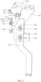
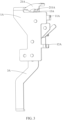
- the indication device includes a mounting bracket 1A, an indicator 2A movably connected to the mounting bracket 1A, and an indicator linkage rod 3A movably connected to the mounting bracket 1A.
- the indicator 2A is configured to have an "ON" indication state position and an "OFF" indication state position, into which the indicator 2A is switchable relative to the mounting bracket 1A.
- the indicator linkage rod 3A is configured to have a closed state position and an open state position, into which the indicator linkage rod 3A is switchable relative to the mounting bracket 1A.
- a first reset member 4A is connected between the indicator 2A and the mounting bracket 1A and configured to allow the indicator 2A to automatically reset from the "ON" indication state position to the "OFF" indication state position.
- a second reset member 5A is connected between the mounting bracket 1A and the indicator linkage rod 3A and configured to allow the indicator linkage rod 3A to automatically reset from the open state position to the closed state position.
- the indicator linkage rod 3A and the indicator 2A are linked through a linkage structure, and a reset force of the second reset member 5A is greater than a reset force of the first reset member 4A.
- the indicator linkage rod 3A drives the indicator 2A from the "OFF" indication state position to the "ON” indication state position through the linkage structure.
- the switching of the indication state switching of the indicator 2A is not simply driven by the indicator linkage rod 3A.
- the first reset member 4A is connected between the indicator 2A and the mounting bracket 1A and configured to allow the indicator 2A to automatically reset from the "ON" indication state position to the "OFF" indication state position.
- the indicator linkage rod 3A drives the indicator 2A through the linkage structure to overcome the reset force of the first reset member 4A and to switch from the "OFF" indication state position to the "ON" indication state position.
- the indicator 2A is automatically reset to the "OFF" indication state position by the first reset member 4A. In this way, through interaction between the first reset member 4A and the second reset member 5A, the indicator 2A can automatically switch the ON/OFF indication state according to an opening/closing state of the circuit breaker.
- the indicator 2A can be effectively controlled to switch synchronously according to the opening/closing state of the circuit breaker, and the indication state switching of the indicator 2A can be stable, accurate, and reliable.
- the indicator 2A is rotatably connected to the mounting bracket 1A through a rotating shaft.
- the first reset member 4A is a torsion spring, which has a first pin and a second pin.
- the torsion spring is fitted over the rotating shaft used for mounting the indicator 2A.
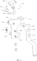
- the mounting bracket 1A is provided with a torsion spring pin fixing portion 11A, and the first pin of the torsion spring is fixed on the torsion spring pin fixing portion 11A of the mounting bracket 1A.
- the indicator 2A is provided with a torsion spring pin socket, and the second pin of the torsion spring is inserted and fixed in the torsion spring pin socket of the indicator 2A.
- a reset force of the torsion spring causes the indicator 2A to have a tendency of reset movement from the "ON" indication state position to the "OFF" indication state position relative to the mounting bracket 1A.
- one end of the indicator 2A is formed with an indication portion 21A with an "ON” marking and an “OFF” marking, and the other end thereof is formed with a bent linkage portion 22A.
- the indicator linkage rod 3A is formed with a linkage shaft 31A that movably abuts against the bent linkage portion 22A of the indicator 2A.
- the linkage structure for swinging and switching of the indication portion 21A from the "OFF" indication state position to the "ON" indication state position is formed by the movable abutment fit between the linkage shaft 31A and the bent linkage portion 22A.
- the indicator linkage rod 3A when the circuit breaker is opened, the indicator linkage rod 3A is configured to rise relative to the mounting bracket 1A from the closed state position to the open state position under a lifting action of a circuit breaker rotating shaft 6A (counterclockwise rotation of the circuit breaker rotating shaft 6A), and the linkage shaft 31A removes a pressure limiting action on the bent linkage portion 22A, so that the indication portion 21A is automatically reset from the "ON" indication state position to the "OFF” indication state position under a reset action of the torsion spring.
- the indicator linkage rod 3A When the circuit breaker is closed, the indicator linkage rod 3A automatically descends to the closed state position relative to the mounting bracket 1A under a reset action of the second reset member 5A, and at the same time, the linkage shaft 31A synchronously descends with the indicator linkage rod 3A, so that the linkage shaft 31A presses against the bent linkage portion 22A, thereby driving the indicator 2A to rotate relative to the mounting bracket 1A, and causing the indicator 2A to swing and switch from the "OFF" indication state position to the "ON" indication state position.
- the linkage structure between the indicator linkage rod 3A and the indicator 2A is not linked by a snap fit as in the related art.
- the indicator linkage rod 3A is formed with the linkage shaft 31A that movably abuts against the bent linkage portion 22A of the indicator 2A, and the movable abutment fit between the linkage shaft 31A and the bent linkage portion 22A forms the linkage structure for swinging and switching of the indication portion 21A from the "OFF" indication state position to the "ON" indication state position.
- the linkage structure works, that is, the linkage shaft 31A presses against the bent linkage portion 22A, thereby driving the indicator 2A to overcome the reset force of the first reset member 4A so as to rotate relative to the mounting bracket 1A, and causing the indication portion 21A to swing and switch from the "OFF" indication state position to the "ON” indication state position.
- the circuit breaker is opened, the indicator linkage rod 3A rises, and the linkage structure does not work.
- the linkage structure formed by the movable abutment fit between the linkage shaft 31A and the bent linkage portion 22A effectively improves the linkage smoothness and stability, greatly reduces the risk of linkage jamming, and further enhancing the stability and reliability of the indication state switching of the indicator 2A, so as to improve the indication accuracy of the indicator 2A.
- the indicator linkage rod 3A is configured to be slidably connected to the mounting bracket 1A and can slide vertically up and down relative to the mounting bracket 1A.
- the second reset member 5A is a tension spring
- the mounting bracket 1A is provided with a tension spring hanging portion 12A. A lower end of the tension spring is hung on the tension spring hanging portion 12A, and an upper end of the tension spring is hung on the linkage shaft 31A of the indicator linkage rod 3A, so that the indicator linkage rod 3A has a tendency to automatically descend and reset from the open state position to the closed state position relative to the mounting bracket 1A.
- a tension force of the tension spring is configured to be greater than a torsion force of the torsion spring, so that when the circuit breaker is closed, the tension spring with the greater tension force will drive the indicator linkage rod 3A to descend relative to the mounting bracket 1A, and then, the linkage shaft 31A presses down on the bent linkage portion 22A of the indicator 2A and causes the indicator 2A to overcome the torsion force of the torsion spring, so as to swing and switch from the "OFF" indication state position to the "ON” indication state position.
- the mounting bracket 1A is formed with a limiting surface 13A
- the indication portion 21A of the indicator 2A is formed with an angle limiting member 211A corresponding to the limiting surface 13A.
- Each of two ends of the angle limiting member 211A forms a limit angle.
- a total travel of an up-down movement of the indicator linkage rod 3A is 3.5 mm to 5 mm, and the indicator 2A is configured such that when the indicator linkage rod 3A moves upward by about 2.5 mm from a lowermost closed position, the linkage shaft 31A of the indicator linkage rod 3A will release the limiting fit with the bent linkage portion 22A of the indicator 2A, and at the same time, the indicator 2A will be stably maintained in the "OFF" indication state position under the reset action of the first reset member 4A and the limiting fit of the angle limiting member 211A and the limiting surface 13A. In this way, even if there is an overtravel problem of upward sliding of the indicator linkage rod 3A, the indicator 2A can safely and accurately display the corresponding state.
- the indicator linkage rod 3A is provided with a first guiding long hole 32A and a second guiding long hole 33A.
- the mounting bracket 1A is provided with a first guiding shaft 14A and a second guiding shaft 15A respectively inserted into the first guiding long hole 32A and the second guiding long hole 33A.
- the indicator linkage rod 3A can smoothly slide up and down relative to the mounting bracket 1A through the guiding fit between the first guiding shaft 14A and the first guiding long hole 32A, as well as the guiding fit between the second guiding shaft 15A and the second guiding long hole 33A.
- the indicator linkage rod 3A may also be slidably connected to the mounting bracket 1A through other conventional sliding connection structures, and is not limited to the specific implementations disclosed in this embodiment.
- an embodiment of the present disclosure also provides a circuit breaker, including the indication device for the stored-energy electric operating mechanism of the circuit breaker according to any of the above embodiments.
- a turntable latching mechanism includes a swinging latch, and an end of the swinging latch is a swing rod in a "J-shaped" inverted hook form that is fitted with a boss.
- the swinging latch hooks the boss, so that rotation of an energy-storage turntable is locked, and an energy-storage sliding block is maintained in a static energy-storage state under a joint action of the stop of the boss of the energy-storage turntable and the force applied by an energy-storage spring.
- the turntable latching mechanism is driven by an electromagnetic drive mechanism, and automatic control over the action of the turntable latching mechanism is achieved through the electromagnetic drive mechanism, thereby realizing automatic unlocking.
- this technical solution lacks a manually controlled unlocking function. If manual control over unlocking of the turntable latching mechanism is required, a set of manual control structures needs to be additionally provided, which makes the overall structure of the circuit breaker more complex.
- the present disclosure provides an energy-storage turntable locking structure for a circuit breaker, and a rotation-stopping assembly of the energy-storage turntable locking structure, which is configured to lock an energy-storage turntable of the circuit breaker, can realize automatic unlocking control and manual unlocking control by using a push-pull electromagnet, thereby forming a manual-automatic integrated unlocking control structure.
- An energy-storage turntable locking structure for a circuit breaker includes: a rotation-stopping assembly configured to lock an energy-storage turntable of the circuit breaker, and a rotation-stopping assembly driving mechanism configured to control action of the rotation-stopping assembly to make the rotation-stopping assembly remove a rotation-stopping locking action on the energy-storage turntable.
- the rotation-stopping assembly driving mechanism is a remotely controllable push-pull electromagnet.
- One end of a sliding assembly of the push-pull electromagnet forms a driving end, which cooperates with the rotation-stopping assembly to control the action of the rotation-stopping assembly; another end of the sliding assembly forms a pressing operation end, and through a pressing operation on the pressing operation end, the driving end is manually controlled to act on the rotation-stopping assembly, so as to form manual unlocking.
- circuit breaker is provided with a manual closing button configured to manually control the sliding assembly of the push-pull electromagnet to drive the rotation-stopping assembly to perform an unlocking action.
- a closing press plate is rotatably disposed inside the circuit breaker, and a free end of the closing press plate is pressed against the pressing operation end of the sliding assembly.
- the manual closing button on the circuit breaker is disposed corresponding to the closing press plate, so that when the manual closing button is pressed, the closing press plate is driven to act by the manual closing button, and then the pressing operation end of the sliding assembly is pressed by using the closing press plate, causing the driving end of the sliding assembly to act on the rotation-stopping assembly, so as to make the rotation-stopping assembly perform an unlocking action.
- the rotation-stopping assembly includes a latch member and a limit member.
- the latch member has a rotation-stopping acting end and a limit fitting end.
- the limit member has an unlocking end and a limiting end.
- the rotation-stopping acting end is configured to cooperate with a boss at a peripheral side of the energy-storage turntable, so as to form a rotation-stopping locking action.
- the rotation-stopping acting end of the latch member is configured to have a tendency to automatically move away from the boss to release the rotation-stopping locking action.
- the unlocking end of the limit member is disposed corresponding to the driving end of the sliding assembly, and the limit member is configured to have a limiting state position and a non-limiting state position relative to the latch member.
- the limiting end of the limit member and the limit fitting end of the latch member cooperate with each other to form a limit to prevent the latch member from automatically unlocking.
- the driving end of the sliding assembly acts on the unlocking end of the limit member to drive the limit member to move to the non-limiting state position
- the limiting end of the limit member and the limit fitting end of the latch member release the limiting fit, and the rotation-stopping acting end of the latch member may automatically disengage from the boss of the energy-storage turntable, thereby removing the rotation-stopping locking action on the energy-storage turntable.
- the latch member is configured to be disposed rotatably relative to the energy-storage turntable, and a rotation axis of the latch member is perpendicular to a rotation axis of the energy-storage turntable.
- a latch member reset spring is connected to the latch member, and through an elastic force of the latch member reset spring, the rotation-stopping acting end of the latch member has a tendency of automatically disengaging from the boss to release the rotation-stopping locking action.
- the limit member is configured to be disposed rotatably relative to the latch member, and a rotation axis of the limit member is parallel to the rotation axis of the latch member.
- a limit member reset spring is connected to the limit member, and through an elastic force of the limit member reset spring, the limit member has a tendency of rotating from the non-limiting state position to the limiting state position.
- the present disclosure also provides a remote-control circuit breaker, including the energy-storage turntable locking structure for the circuit breaker according to any of the above embodiments.
- the push-pull electromagnet when electrically-operated energy storage is completed and remote automatic control over unlocking of the energy-storage turntable is required, the push-pull electromagnet is energized, and the sliding assembly of the push-pull electromagnet may automatically extend, so that the driving end of the sliding assembly automatically presses against and acts on the rotation-stopping assembly, thereby automatically removing the rotation-stopping locking action of the rotation-stopping assembly on the energy-storage turntable.
- the energy-storage turntable locking structure can integrate manual unlocking control and automatic unlocking control to form a manual-automatic integrated unlocking control structure, which eliminates the need to separately set up a manual unlocking control structure and does not occupy too much of the limited space inside the circuit breaker.
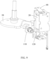
- an embodiment of the present disclosure provides an energy-storage turntable locking structure for a circuit breaker, including a rotation-stopping assembly 1B configured to lock an energy-storage turntable 3B of the circuit breaker, and a rotation-stopping assembly driving mechanism configured to control action of the rotation-stopping assembly 1B to make the rotation-stopping assembly 1B remove a rotation-stopping locking action on the energy-storage turntable 3B.
- the rotation-stopping assembly driving mechanism is a remotely controllable push-pull electromagnet 2B.
- a sliding assembly 21B of the push-pull electromagnet 2B forms a driving end 211B, which cooperates with the rotation-stopping assembly 1B to control the action of the rotation-stopping assembly 1B; another end of the sliding assembly 21B forms a pressing operation end 212B, and through a pressing operation on the pressing operation end 212B, the driving end 211B is manually controlled to act on the rotation-stopping assembly 1B, so as to form manual unlocking.
- the push-pull electromagnet 2B when electrically-operated energy storage is completed and remote automatic control over unlocking of the energy-storage turntable is required, the push-pull electromagnet 2B is energized, and the sliding assembly 21B of the push-pull electromagnet 2B may automatically extend, so that the driving end 211B of the sliding assembly automatically presses against and acts on the rotation-stopping assembly 1B, thereby automatically removing the rotation-stopping locking action of the rotation-stopping assembly 1B on the energy-storage turntable 3B.
- the energy-storage turntable locking structure can integrate manual unlocking control and automatic unlocking control to form a manual-automatic integrated unlocking control structure, which eliminates the need to separately set up a manual unlocking control structure and does not occupy too much of the limited space inside the circuit breaker.
- the circuit breaker is provided with a manual closing button 5B configured to manually control the sliding assembly 21B of the push-pull electromagnet 2B to drive the rotation-stopping assembly 1B to perform an unlocking action.
- a closing press plate 4B is rotatably disposed inside the circuit breaker, and a free end of the closing press plate 4B is pressed against the pressing operation end 212B of the sliding assembly 21B.
- the manual closing button 5B on the circuit breaker is disposed corresponding to the closing press plate 4B, so that when the manual closing button 5B is pressed, the closing press plate 4B is driven to act by the manual closing button 5B, and then the pressing operation end 212B of the sliding assembly 21B is pressed by using the closing press plate 4B, causing the driving end 211B of the sliding assembly 21B to act on the rotation-stopping assembly 1B, so as to make the rotation-stopping assembly 1B perform an unlocking action.
- the rotation-stopping assembly 1B includes a latch member 11B and a limit member 12B.
- the latch member 11B has a rotation-stopping acting end 111B and a limit fitting end 112B.
- the limit member 12B has an unlocking end 121B and a limiting end 122B.
- the rotation-stopping acting end 111B is configured to cooperate with a boss 31B at a peripheral side of the energy-storage turntable 3B, so as to form a rotation-stopping locking action.
- the rotation-stopping acting end 111B of the latch member 11B is configured to have a tendency to automatically move away from the boss 31B to release the rotation-stopping locking action.
- the unlocking end 121B of the limit member 12B is disposed corresponding to the driving end 211B of the sliding assembly 21B, and the limit member 12B is configured to have a limiting state position and a non-limiting state position relative to the latch member 11B.
- the limit member 12B is in the limiting state position, the limiting end 122B of the limit member 12B and the limit fitting end 112B of the latch member 11B cooperate with each other to form a limit to prevent the latch member 11B from automatically unlocking.
- the driving end 211B of the sliding assembly 21B acts on the unlocking end 121B of the limit member 12B to drive the limit member 12B to move to the non-limiting state position
- the limiting end 122B of the limit member 12B and the limit fitting end 112B of the latch member 11B release the limiting fit, and the rotation-stopping acting end 111B of the latch member 11B may automatically disengage from the boss 31B of the energy-storage turntable 3B, thereby removing the rotation-stopping locking action on the energy-storage turntable 3B.
- the latch member 11B itself is configured to have an automatic unlocking movement trend, while the limit member 12B restricts the automatic unlocking of the latch member 11B, that is, there is no direct linkage structure between the latch member 11B and the limit member 12B.
- the limit fitting end 112B of the latch member 11B is merely movably lapped on the limiting end 122B of the limit member 12B.
- the overall structure of the rotation-stopping assembly 1B is simple, efficient, and stable, which helps to ensure the stability and reliability of its unlocking action.
- the rotation-stopping assembly 1B may also be of other structures (such as a relevant rotation-stopping locking structure in CN216957932U , or other rotation-stopping locking structures in the related art that may realize limiting fit with the boss of the energy-storage turntable to produce the rotation-stopping locking action on the energy-storage turntable), as long as the rotation-stopping locking structure may be limited and fitted with the boss of the energy-storage turntable to produce the rotation-stopping locking action on the energy-storage turntable and may automatically remove the rotation-stopping locking action on the energy-storage turntable under the pushing of the sliding assembly 21B of the push-pull electromagnet 2B, which is not limited to the specific implementations disclosed in this embodiment.
- the latch member 11B is configured to be disposed rotatably relative to the energy-storage turntable 3B, and a rotation axis of the latch member 11B is perpendicular to a rotation axis of the energy-storage turntable 3B.
- a latch member reset spring 113B is connected to the latch member 11B, and through an elastic force of the latch member reset spring 113B, the rotation-stopping acting end 111B of the latch member 11B has a tendency of automatically disengaging from the boss 31B to release the rotation-stopping locking action.
- the limit member 12B is configured to be disposed rotatably relative to the latch member 11B, and a rotation axis of the limit member 12B is parallel to the rotation axis of the latch member 11B.
- a limit member reset spring 123B is connected to the limit member 12B, and through an elastic force of the limit member reset spring 123B, the limit member 12B has a tendency of rotating from the non-limiting state position to the limiting state position.
- a movement direction of the rotation-stopping acting end 111B of the latch member 11B and a rotation path of the boss 31B of the energy-storage turntable 3B are not in a common plane, but are separately in two planes perpendicular to each other, which makes the locking effect of the latch member 11B on the energy-storage turntable 3B more stable and reliable, and the unlocking control more convenient.
- the swinging latch and the boss of the energy-storage turntable rotate in the common plane, so that the disengagement force between the swinging latch and the energy-storage turntable will be much greater than a theoretical value; and if a manual control structure for controlling manual action of the swinging latch is directly disposed on the swinging latch in the related art, the large disengagement force of the swinging latch will make it difficult to operate a manual unlocking structure, resulting in difficulty in manual unlocking.
- the rotation axis of the latch member 11B in the present application is perpendicular to the rotation axis of the energy-storage turntable 3B, so that a disengagement force between the latch member 11B and the energy-storage turntable 3B is much smaller than the disengagement force between the swinging latch and the energy-storage turntable in the related art, making a disengagement operation stable and easy to control.
- remote automatic control it is not necessary to provide a high-power electromagnet to push the latch member 11B to move for the disengagement unlocking operation, which facilitates cost reduction.
- an embodiment of the present disclosure also provides a remote-control circuit breaker, including the energy-storage turntable locking structure for the circuit breaker according to any of the above embodiments.
- a stored-energy electric operating padlock plate can still be pulled out when an operation mode switching lever (equivalent to a three-position selector) is in a remote state position and in a local state position, which poses a potential safety hazard during use.
- the present disclosure provides a padlock module for a remote-control circuit breaker.
- a padlock module for a remote-control circuit breaker.
- a padlock module for a remote-control circuit breaker includes a fixed bracket, a three-position selector, and a padlock plate.
- the three-position selector and the padlock plate are movably disposed on the fixed bracket, and the three-position selector on the fixed bracket is configured to have a remote state position, a local state position, and a locked state position, into which the three-position selector is toggle-switchable.
- the padlock plate is provided with a first limit portion, and the three-position selector is provided with a second limit portion, the first limit portion being disposed corresponding to the second limit portion.
- the first limit portion and the second limit portion form a limiting fit, so that the padlock plate cannot be pulled out for used relative to the fixed bracket.
- the first limit portion and the second limit portion release the limiting fit, so that the padlock plate can be normally pulled out for use relative to the fixed bracket.
- the three-position selector is disposed on the fixed bracket in a transversely slidable manner
- the padlock plate is disposed on the fixed bracket in a vertically slidable manner. Only when the three-position selector is transversely toggled to the locked state position, the second limit portion on the three-position selector moves away from the first limit portion of the padlock plate, to remove the pressure limiting fit between the first limit portion and the second limit portion, so that the padlock plate can be vertically pulled out for use relative to the fixed bracket.
- the first limiting portion is a transverse barrier structure transversely disposed at a side edge of the padlock plate
- the second limiting portion is a stop angle structure correspondingly disposed at a top position of the transverse barrier.
- a reset spring is connected between the fixed bracket and the padlock plate, and a reset force of the reset spring causes the padlock plate to have a tendency to automatically pop out vertically for padlocking relative to the fixed bracket.
- a limit hook is rotatably disposed on the fixed bracket, one end of the limit hook being formed with a hook portion and another end of the limit hook forming a linkage portion.
- the padlock plate is provided with a limit protrusion.
- the remote-control circuit breaker has an energy-storage sliding block that can switch between an energy-storage state position and a non-energy-storage state position.
- the energy-storage sliding block is connected to the linkage portion of the limit hook, to drive the limit hook to swing under the action of the energy-storage sliding block.
- the hook portion of the limit hook hooks the limit protrusion of the padlock plate, so that the padlock plate cannot be pulled out for use.
- the energy-storage sliding block drives the limit hook to swing, and causes the hook portion to release the limit protrusion, so that when the three-position selector is in the locked state position and the energy-storage sliding block is in the energy-storage state position, the padlock plate can be pulled out for use relative to the fixed bracket.
- the limit hook is rotatably connected to the fixed bracket near a middle position through a rotating shaft structure.
- the fixed bracket is provided with a tripping plate for manual tripping and opening of the circuit breaker.
- the tripping plate is disposed on the fixed bracket in a vertically slidable manner, and is provided with a limit rod corresponding to the limit hook.
- the present disclosure also provides a remote-control circuit breaker, including the padlock module for the remote-control circuit breaker according to any of the above embodiments.
- the padlock plate cannot be pulled out for use relative to the fixed bracket; only when the three-position selector is toggled to the locked state position, the first limit portion and the second limit portion release the pressure limiting fit, and the padlock plate can be normally pulled out for use relative to the fixed bracket. In this way, the problem that the three-position selector can be pulled out for use even when it is in the remote state position or the local state position can be effectively avoided.
- an embodiment of the present disclosure provides a padlock module for a remote-control circuit breaker, including a fixed bracket 1C, a three-position selector 2C, and a padlock plate 3C.
- the three-position selector 2C and the padlock plate 3C are movably disposed on the fixed bracket 1C, and the three-position selector 2C on the fixed bracket 1C is configured to have a remote state position, a local state position, and a locked state position, into which the three-position selector is toggle-switchable (in order to more directly and clearly display specific positions of the three-position selector 2C in three different mode states, the three-position selector in three different mode state positions is directly shown in FIGS. 12 to 14 ).
- the padlock plate 3C is provided with a first limit portion 31C, and the position selector 2C is provided with a second limit portion 21C, the first limit portion 31C being disposed corresponding to the second limit portion 21C.
- the first limit portion 31C and the second limit portion 21C form a limiting fit, so that the padlock plate 3C cannot be pulled out for use relative to the fixed bracket 1C.
- the first limit portion 31C and the second limit portion 21C release the limiting fit, so that the padlock plate can be pulled out for use relative to the fixed bracket 1C.
- the padlock plate 3C cannot be pulled out for use relative to the fixed bracket; only when the three-position selector 2C is toggled to the locked state position, the first limit portion 31C and the second limit portion 21C release the pressure limiting fit, and the padlock plate 3C can be normally pulled out for use relative to the fixed bracket. In this way, the problem that the three-position selector 2C can be pulled out for use even when it is in the remote state position or the local state position can be effectively avoided.
- the three-position selector 2C is disposed on the fixed bracket 1C in a transversely slidable manner
- the padlock plate 3C is disposed on the fixed bracket 1C in a vertically slidable manner. Only when the three-position selector 2C is transversely toggled to the locked state position, the second limit portion 21C on the three-position selector 2C moves away from the first limit portion 31C of the padlock plate 3C, to remove the pressure limiting fit between the first limit portion 31C and the second limit portion 21C, so that the padlock plate 3C can be vertically pulled out for use relative to the fixed bracket 1C.
- the arrangement of the three-position selector 2C and the padlock plate 3C on the fixed bracket 1C is not limited to the specific implementations disclosed in this embodiment, as long as the first limit portion 31C and the second limit portion 21C can release the limiting fit when the three-position selector 2C is toggled to the locked state position, and the first limit portion 31C and the second limit portion 21C can form the limiting fit when the three-position selector 2C is toggled to the remote state position or the local state position.
- the first limiting portion 31C is a transverse barrier structure transversely disposed at a side edge of the padlock plate
- the second limiting portion 21C is a stop angle structure correspondingly disposed at a top position of the transverse barrier.
- first limit portion 31C and the second limit portion 21C are not limited to the specific implementations disclosed in this embodiment, and may also be of other relevant structures that can cooperate with each other to form the limit, as long as the first limit portion 31C and the second limit portion 21C can release the limiting fit when the three-position selector 2C is toggled to the locked state position, and the first limit portion 31C and the second limit portion 21C can form the limiting fit when the three-position selector 2C is toggled to the remote state position or the local state position.
- a reset spring 4C is connected between the fixed bracket 1C and the padlock plate 3C, and a reset force of the reset spring 4C causes the padlock plate 3C to have a tendency to automatically pop out vertically for padlocking relative to the fixed bracket 1C.
- the padlock plate 3C will automatically pop up vertically for padlocking relative to the fixed bracket 1C.
- a limit hook 5C is rotatably provided on the fixed bracket 1C.
- One end of the limit hook 5C is formed with a hook portion 51C, and another end of the limit hook 5C forms a linkage portion 52C.
- the padlock plate 3C is provided with a limit protrusion 32C.
- the remote-control circuit breaker has an energy-storage sliding block 6C that can switch between an energy-storage state position and a non-energy-storage state position.
- the energy-storage sliding block 6C is connected to the linkage portion 52C of the limit hook 5C, to drive the limit hook 5C to swing under the action of the energy-storage sliding block 6C.
- the hook portion 51C of the limit hook 5C hooks the limit protrusion 32C of the padlock plate 3C, so that the padlock plate 3C cannot be pulled out for use.
- the energy-storage sliding block 6C drives the limit hook 5C to swing, and causes the hook portion 51C to release the limit protrusion 32C, so that when the three-position selector 2C is in the locked state position and the energy-storage sliding block 6C is in the energy-storage state position, the padlock plate 3C can be pulled out for use relative to the fixed bracket 1C.
- the limit hook 5C is rotatably connected to the fixed bracket 1C near a middle position through a rotating shaft structure.
- the fixed bracket 1C is provided with the limit hook 5C that is linked with the energy-storage sliding block 6C, and the limit hook 5C is configured to be linked with the opening/closing state of the circuit breaker, when the energy-storage sliding block 6C is in the non-energy-storage state position, the hook portion 51C of the limit hook 5C hooks the limit protrusion 32C of the padlock plate 3C, so that the padlock plate 3C cannot be pulled out for use; only when the three-position selector 2C is in the locked state position and the energy-storage sliding block 6C is in the energy-storage state position, the padlock plate 3C can be normally pulled out for padlocking relative to the fixed bracket 1C.
- the fixed bracket 1C is provided with a tripping plate 7C for manual tripping and opening of the circuit breaker.
- the tripping plate 7C is disposed on the fixed bracket 1C in a vertically slidable manner, and is provided with a limit rod 71C corresponding to the limit hook 5C.
- the limit hook 5C produces a stopping effect on the limit rod 71C to prevent the tripping plate 7C from being pressed.
- the tripping plate 7C is provided with the limit rod 71C corresponding to the limit hook 5C, and the limit hook 5C is configured to be linked with the opening/closing state of the circuit breaker, through the cooperation of the limit rod 71C and the limit hook 5C, when the energy-storage sliding block 6C is in the non-energy-storage state position, the tripping plate 7C can be pressed normally to manually control tripping of the circuit breaker body.
- the limit hook 5C produces a stopping effect on the limit rod 71C to prevent the tripping plate 7C from being pressed. That is, when the circuit breaker is in the energy-storage state, a local tripping operation cannot be performed by pressing the tripping plate 7C.
- an embodiment of the present disclosure also provides a remote-control circuit breaker, including the padlock module for the remote-control circuit breaker according to any of the above embodiments.
- the present disclosure provides a driving mechanism for a manual energy-storage structure of a circuit breaker, which mainly solves the technical problem that the use of the traction rope for transmission between the energy-storage handle and the pawl driven turntable in the related art is prone to poor consistency of the traction transmission and leads to unreliable and unstable driving of the pawl driven turntable by the energy-storage handle.
- a driving mechanism for a manual energy-storage structure of a circuit breaker includes a pawl driven turntable configured to cooperate with a pawl in a ratchet pawl mechanism of the manual energy-storage structure of the circuit breaker to drive the pawl to rotate a ratchet.
- An energy-storage handle is also rotatably disposed on a mounting plate of the circuit breaker, and transmission connection between the energy-storage handle and the pawl driven turntable is realized by a connecting rod transmission structure.
- the mounting plate is provided with a bracket, and the energy-storage handle is rotatably connected to the bracket to form a lever structure.
- One end of the energy-storage handle forms an operating end, and another end of the energy-storage handle forms an acting end.
- a transverse sliding block is slidably disposed on the bracket, and a first connecting rod is movably connected between the acting end of the energy-storage handle and the transverse sliding block.
- a second connecting rod is movably connected between the transverse sliding block and the pawl driven turntable.
- the connecting rod transmission structure is formed by mutual cooperation between the first connecting rod, the transverse sliding block, and the second connecting rod. The movement of the energy-storage handle is converted into the rotation of the pawl driven turntable through the connecting rod transmission structure, and the pawl driven turntable is used to drive the ratchet to rotate.
- the bracket is provided with a U-shaped transverse sliding groove, and the transverse sliding block is slidably disposed in the U-shaped transverse sliding groove.
- a guiding long hole parallel to a sliding direction of the transverse sliding block is provided in a side wall of the U-shaped transverse sliding groove.
- a rotating shaft is connected to the transverse sliding block; a shaft sleeve is connected to an end of the rotating shaft; and the shaft sleeve is adapted to be movably embedded in the guiding long hole.
- the transverse sliding of the transverse sliding block in the U-shaped transverse sliding groove is guided by mutual cooperation between the shaft sleeve and the guiding long hole, so that when the energy-storage handle is triggered, the acting end of the energy-storage handle drives the transverse sliding block to act through the first connecting rod, and then the transverse sliding block drives the second connecting rod to act, thereby driving the pawl driven turntable to rotate.
- the bracket is provided with a handle mounting shaft, and the energy-storage handle is rotatably connected to the bracket through the handle mounting shaft, to form a lever structure.
- the energy-storage handle is made of a plastic material.
- transverse sliding block is made of a plastic material.
- the present disclosure also provides a circuit breaker including the driving mechanism for the manual energy-storage structure of the circuit breaker according to any of the above embodiments.
- the transmission between the energy-storage handle and the pawl driven turntable is more stable and consistent compared to the scheme of using the traction rope in the related art.
- the technical scheme of using the traction rope in the related art can only achieve one-way transmission due to the flexibility of the traction rope, but using the connecting rod structure for transmission can achieve two-way transmission and produce better transmission effect.
- an embodiment of the present disclosure provides a driving mechanism for a manual energy-storage structure of a circuit breaker.
- the driving mechanism includes a pawl driven turntable 2D configured to cooperate with a pawl in a ratchet pawl mechanism 1D of the manual energy-storage structure of the circuit breaker to drive the pawl to rotate a ratchet.
- An energy-storage handle 4D is also rotatably disposed on a mounting plate 3D of the circuit breaker, and transmission connection between the energy-storage handle 4D and the pawl driven turntable 2D is realized by a connecting rod transmission structure 5D.
- the transmission between the energy-storage handle 4D and the pawl driven turntable 2D through the connecting rod transmission structure 5D due to the transmission connection between the energy-storage handle 4D and the pawl driven turntable 2D through the connecting rod transmission structure 5D, and due to the structural characteristics of the connecting rod structure (stable transmission connection and consistent transmission), the transmission between the energy-storage handle 4D and the pawl driven turntable 2D is more stable compared to the scheme of using the traction rope (which may undergo slight elastic deformation during use) in the related art.
- the technical scheme of using the traction rope in the related art can only achieve one-way transmission due to the flexibility of the traction rope, but using the connecting rod structure for transmission can achieve two-way transmission and produce better transmission effect.
- the mounting plate 3D is provided with a bracket 6D, and the energy-storage handle 4D is rotatably connected to the bracket 6D to form a lever structure.
- One end of the energy-storage handle 4D forms an operating end, and another end of the energy-storage handle 4D forms an acting end.
- a transverse sliding block 51D is slidably disposed on the bracket 6D, and a first connecting rod 52D is movably connected between the acting end of the energy-storage handle 4D and the transverse sliding block 51D.
- a second connecting rod 53D is movably connected between the transverse sliding block 51D and the pawl driven turntable 2D.
- the connecting rod transmission structure 5D is formed by mutual cooperation between the first connecting rod 52D, the transverse sliding block 51D, and the second connecting rod 53D.
- the movement of the energy-storage handle 4D is converted into the rotation of the pawl driven turntable 2D through the connecting rod transmission structure 5D, and the pawl driven turntable 2D is used to drive the ratchet to rotate.
- both ends of the first connecting rod 52D and both ends of the second connecting rod 53D are movably connected (rotatably connected), ensuring that the connecting rod transmission structure 5D has sufficient freedom of movement to achieve stable transmission between the energy-storage handle 4D and the pawl driven turntable 2D.
- mating structures between the transverse sliding block 51D and the second connecting rod 53D may also be replaced by an integral stamped part as shown in FIG. 20 , and is not limited to the specific implementations disclosed in this embodiment.
- the bracket 6D is provided with a U-shaped transverse sliding groove, and the transverse sliding block 51D is slidably disposed in the U-shaped transverse sliding groove.
- a guiding long hole 61D parallel to a sliding direction of the transverse sliding block 51D is provided in a side wall of the U-shaped transverse sliding groove.
- a rotating shaft is connected to the transverse sliding block 51D; a shaft sleeve is connected to an end of the rotating shaft; and the shaft sleeve is adapted to be movably embedded in the guiding long hole 61D.
- the transverse sliding of the transverse sliding block 51D in the U-shaped transverse sliding groove is guided by mutual cooperation between the shaft sleeve and the guiding long hole 61D, so that when the energy-storage handle 4D is triggered, the acting end of the energy-storage handle 4D drives the transverse sliding block 51D to act through the first connecting rod 52D, and then the transverse sliding block 51D drives the second connecting rod 53D to act, thereby driving the pawl driven turntable 2D to rotate.
- the transverse sliding block 51D may also be slidably disposed on the bracket 6D through other conventional sliding connection structures, as long as the transverse sliding block 51D can slide reciprocally along a straight line on the bracket 6D in a predetermined direction, which will not be limited to the specific implementations disclosed in this embodiment and instead can be set by those skilled in the art according to specific needs.
- the bracket 6D is provided with a handle mounting shaft, and the energy-storage handle 4D is rotatably connected to the bracket 6D through the handle mounting shaft, to form a lever structure.
- the energy-storage handle 4D is made of a plastic material; and the transverse sliding block 51D is made of a plastic material.
- the energy-storage handle 4D and the transverse sliding block 51D may also be made of other insulating materials, which will not be limited to the specific implementations disclosed in this embodiment.
- an embodiment of the present disclosure also provides a circuit breaker, including the driving mechanism for the manual energy-storage structure of the circuit breaker according to any of the above embodiments.
- a remote-control circuit breaker with a stored-energy electric operating mechanism in the related art, even if an operation mode switching lever (equivalent to a three-position selector) is toggled to a remote state position, an energy-storage handle may still be triggered, resulting in a potential safety hazard that the remote-control circuit breaker can still perform a local opening operation through the energy-storage handle in a remote-control mode.
- an operation mode switching lever equivalent to a three-position selector
- the present disclosure provides an energy-storage handle locking mechanism for a manual energy-storage structure of a circuit breaker.
- a locking rod between an energy-storage handle and a three-position selector when the three-position selector is toggled to a remote state position, the three-position selector will control the locking rod to act and lock the energy-storage handle, making it inoperable.
- An energy-storage handle locking mechanism for a manual energy-storage structure of a circuit breaker includes a cover shell covering a mounting plate of the circuit breaker.
- a three-position selector of the circuit breaker and an energy-storage handle of the manual energy-storage structure are configured to be disposed oppositely inside the cover shell.
- a locking rod is slidably disposed between the energy-storage handle and the three-position selector and at an inner side of the cover shell. One end of the locking rod forms a locking portion, and another end thereof forms a driving portion.
- the energy-storage handle is provided with a locking hole corresponding to the locking portion.
- the three-position selector is provided with a pushing portion corresponding to the driving portion.
- the pushing portion acts on the driving portion to move the locking rod as a whole, and the locking portion is correspondingly inserted into the locking hole of the energy-storage handle to lock the energy-storage handle.
- a mounting bracket is disposed at the inner side of the cover shell, and the locking rod is slidably disposed on the mounting bracket.
- the locking rod is provided with a first guiding long hole and a second guiding long hole.
- the mounting bracket is provided with a first guiding shaft and a second guiding shaft that are respectively inserted into the first guiding long hole and the second guiding long hole.
- the locking rod smoothly moves transversely relative to the mounting bracket through the guiding fit between the first guiding shaft and the first guiding long hole as well as the guiding fit between the second guiding shaft and the second guiding long hole.
- a reset spring is disposed between the mounting bracket and the locking rod to automatically reset the locking rod toward a direction of unlocking.
- the driving portion has a wedge-shaped structure with an inclined guiding surface.
- the cover shell is provided with an energy-storage handle avoidance slot disposed corresponding to the energy-storage handle and a position-selection operating portion avoidance slot disposed corresponding to a position-selection operating portion of the three-position selector.
- the three-position selector of the circuit breaker and the energy-storage handle of the manual energy-storage structure are configured to be disposed oppositely in sub-marginal positions at both sides inside the cover shell.
- the present disclosure also provides a circuit breaker, including the energy-storage handle locking mechanism for the manual energy-storage structure of the circuit breaker according to any of the above embodiments.
- the three-position selector since the locking rod is disposed between the energy-storage handle and the three-position selector, when the three-position selector is toggled to the remote state position, the three-position selector will control the locking rod to act and lock the energy-storage handle, making it inoperable. That is, when the circuit breaker is in the remote state mode, users cannot operate the energy-storage handle for local operation, greatly improving the safety of using the circuit breaker.
- an embodiment of the present disclosure provides an energy-storage handle locking mechanism for a manual energy-storage structure of a circuit breaker, including a cover shell 1E covering a mounting plate of the circuit breaker.
- a three-position selector 2E of the circuit breaker and an energy-storage handle 3E of the manual energy-storage structure are configured to be disposed oppositely inside the cover shell 1E.
- a locking rod 4E is slidably disposed between the energy-storage handle 3E and the three-position selector 2E and at an inner side of the cover shell 1E.
- One end of the locking rod 4E forms a locking portion 41E, and another end thereof forms a driving portion 42E.
- the energy-storage handle 3E is provided with a locking hole corresponding to the locking portion 41E.
- the three-position selector 2E is provided with a pushing portion 21E corresponding to the driving portion 42E. Only when the three-position selector 2E is toggled to a remote state position, the pushing portion 21E acts on the driving portion 42E to move the locking rod 4E as a whole, and the locking portion 41E is correspondingly inserted into the locking hole of the energy-storage handle 3E to lock the energy-storage handle 3E.
- the locking rod 4E is disposed between the energy-storage handle 3E and the three-position selector 2E, when the three-position selector 2E is toggled to the remote state position, the three-position selector 2E will control the locking rod 4E to act and lock the energy-storage handle 3E, making it inoperable. That is, when the circuit breaker is in the remote state mode, users cannot operate the energy-storage handle 3E for local operation, greatly improving the safety of using the circuit breaker.
- a mounting bracket 5E is disposed at the inner side of the cover shell 1E, and the locking rod 4E is slidably disposed on the mounting bracket 5E.
- the locking rod 4E is provided with a first guiding long hole 43E and a second guiding long hole 44E;
- the mounting bracket 5E is provided with a first guiding shaft 51E and a second guiding shaft 52E that are respectively inserted into the first guiding long hole 43E and the second guiding long hole 44E; and the locking rod 4E smoothly moves transversely relative to the mounting bracket 5E through the guiding fit between the first guiding shaft S 1E and the first guiding long hole 43E as well as the guiding fit between the second guiding shaft 52E and the second guiding long hole 44E.
- the locking rod 4E may also be slidably disposed on the mounting bracket 5E through other conventional sliding connection structures, such as a slide-groove slide-rail fitting structure, which will not be limited to the specific implementations disclosed in this embodiment and instead can be set by those skilled in the art according to specific needs.
- a reset spring 6E is disposed between the mounting bracket 5E and the locking rod 4E to automatically reset the locking rod 4E toward a direction of unlocking.
- the locking rod 4E can automatically remove a locking action on the energy-storage handle 3E, avoiding affecting the normal use of the energy-storage handle 3E.
- the driving portion 42E has a wedge-shaped structure with an inclined guiding surface.
- a vertical movement of the three-position selector 2E is converted into a transverse movement of the locking rod 4E by mutual cooperation between the pushing portion 21E and the driving portion 42E of the wedge-shaped structure, to allow the three-position selector 2E at a specific state position to push the locking rod 4E to move.
- the mating structure between the pushing portion 21E and the driving portion 42E is not limited to the specific implementations disclosed in this embodiment, as long as when the three-position selector 2E is toggled to the remote state position, its pushing portion 21E can act on the driving portion 42E to push the locking rod 4E to move as a whole, so that the end of the locking rod 4E is inserted into the locking hole of the energy-storage handle 3E to achieve locking.
- the cover shell 1E is provided with an energy-storage handle avoidance slot disposed corresponding to the energy-storage handle 3E and a position-selection operating portion avoidance slot disposed corresponding to a position-selection operating portion of the three-position selector 2E.
- the three-position selector 2E of the circuit breaker and the energy-storage handle 3E of the manual energy-storage structure are configured to be disposed oppositely in sub-marginal positions at both sides inside the cover shell 1E.
- a side wall of the handle avoidance slot of the cover shell 1E is provided with a through hole disposed corresponding to the end of the locking rod 4E, such that when the three-position selector 2E is toggled to the remote state position, the three-position selector 2E will control the locking rod 4E to act, and hence allow the end of the locking rod 4E to be inserted through the corresponding through hole into the locking hole of the energy-storage handle 3E, thereby locking the energy-storage handle 3E and making it inoperable.
- an embodiment of the present disclosure also provides a circuit breaker, including the energy-storage handle locking mechanism for the manual energy-storage structure of the circuit breaker according to any of the above embodiments.
- the circuit breaker is of a remote-control circuit breaker structure.
Landscapes
- Breakers (AREA)
Applications Claiming Priority (5)
| Application Number | Priority Date | Filing Date | Title |
|---|---|---|---|
| CN202311580323.8A CN117457447A (zh) | 2023-11-23 | 2023-11-23 | 一种断路器储能电动操作机构的指示装置及断路器 |
| CN202323181260.7U CN221447084U (zh) | 2023-11-23 | 2023-11-23 | 一种断路器的储能转盘锁定结构及远程控制断路器 |
| CN202323165310.2U CN221447082U (zh) | 2023-11-23 | 2023-11-23 | 一种断路器手动储能结构用的驱动机构及断路器 |
| CN202311580862.1A CN117438257A (zh) | 2023-11-23 | 2023-11-23 | 一种远程控制断路器的挂锁模块及远程控制断路器 |
| CN202323181042.3U CN221447083U (zh) | 2023-11-23 | 2023-11-23 | 一种断路器手动储能结构用的储能手柄锁定机构及断路器 |
Publications (1)
| Publication Number | Publication Date |
|---|---|
| EP4560672A1 true EP4560672A1 (de) | 2025-05-28 |
Family
ID=93648167
Family Applications (1)
| Application Number | Title | Priority Date | Filing Date |
|---|---|---|---|
| EP24214388.1A Pending EP4560672A1 (de) | 2023-11-23 | 2024-11-21 | Anzeigevorrichtung für elektrischen betriebsmechanismus eines schutzschalters mit gespeicherter energie und schutzschalter |
Country Status (1)
| Country | Link |
|---|---|
| EP (1) | EP4560672A1 (de) |
Citations (5)
| Publication number | Priority date | Publication date | Assignee | Title |
|---|---|---|---|---|
| DE20121223U1 (de) * | 2001-10-30 | 2003-03-06 | Siemens AG, 80333 München | Antriebsstrang für einen bewegbaren Kontakt eines elektrischen Schalters |
| US20120061224A1 (en) * | 2010-09-09 | 2012-03-15 | Eaton Industries Gmbh | Indicator device of a circuit breaker |
| CN202796784U (zh) * | 2012-09-26 | 2013-03-13 | 法泰电器(江苏)股份有限公司 | 断路器触头状态指示机构 |
| CN211980535U (zh) * | 2020-06-18 | 2020-11-20 | 浙江德菱科技股份有限公司 | 分合闸指示装置 |
| CN216957932U (zh) | 2021-10-19 | 2022-07-12 | 厦门宏发开关设备有限公司 | 储能式电动操作机构以及远程控制断路器 |
-
2024
- 2024-11-21 EP EP24214388.1A patent/EP4560672A1/de active Pending
Patent Citations (5)
| Publication number | Priority date | Publication date | Assignee | Title |
|---|---|---|---|---|
| DE20121223U1 (de) * | 2001-10-30 | 2003-03-06 | Siemens AG, 80333 München | Antriebsstrang für einen bewegbaren Kontakt eines elektrischen Schalters |
| US20120061224A1 (en) * | 2010-09-09 | 2012-03-15 | Eaton Industries Gmbh | Indicator device of a circuit breaker |
| CN202796784U (zh) * | 2012-09-26 | 2013-03-13 | 法泰电器(江苏)股份有限公司 | 断路器触头状态指示机构 |
| CN211980535U (zh) * | 2020-06-18 | 2020-11-20 | 浙江德菱科技股份有限公司 | 分合闸指示装置 |
| CN216957932U (zh) | 2021-10-19 | 2022-07-12 | 厦门宏发开关设备有限公司 | 储能式电动操作机构以及远程控制断路器 |
Similar Documents
| Publication | Publication Date | Title |
|---|---|---|
| KR102475979B1 (ko) | 잠금 여부 표시 기능이 구비된 창호용 잠금장치 | |
| US7399934B2 (en) | External operation handle device | |
| KR101434980B1 (ko) | 래치장치 | |
| CN207966888U (zh) | 一种漏电断路器 | |
| CN110600336B (zh) | 一种带漏电指示机构的漏电断路器 | |
| CN209544998U (zh) | 一种开关柜的抽屉联锁装置 | |
| JP2022502147A (ja) | ドアロック及びドアロック用制御回路 | |
| CN113421804B (zh) | 一种用于断路器的储能式操作机构 | |
| EP4560672A1 (de) | Anzeigevorrichtung für elektrischen betriebsmechanismus eines schutzschalters mit gespeicherter energie und schutzschalter | |
| CN218215026U (zh) | 一种自动转换开关装置 | |
| JP4118987B2 (ja) | 扉用錠止装置 | |
| CN205723215U (zh) | 具有转换指示的辅助模块 | |
| CN220821442U (zh) | 断路器的脱扣指示结构及断路器 | |
| CN218039075U (zh) | 一种插入式断路器 | |
| CN114783840A (zh) | 应用于旋转式电动机断路器上的旋钮机构 | |
| CN115360065A (zh) | 一种插入式断路器 | |
| CN223296753U (zh) | 断路器 | |
| CN119517695B (zh) | 断路器的脱扣指示结构及断路器 | |
| CN223023182U (zh) | 一种带锁定结构的断路器 | |
| CN221447083U (zh) | 一种断路器手动储能结构用的储能手柄锁定机构及断路器 | |
| JPS6136061Y2 (de) | ||
| CN206819899U (zh) | 手操装置、断路器和电气柜 | |
| JP2924849B2 (ja) | 電動シャッターの手動・電動切替装置 | |
| CN113380589B (zh) | 操作手柄和断路器手动操作机构手柄自锁结构 | |
| CN224190826U (zh) | 一种开关的面板组件及开关 |
Legal Events
| Date | Code | Title | Description |
|---|---|---|---|
| PUAI | Public reference made under article 153(3) epc to a published international application that has entered the european phase |
Free format text: ORIGINAL CODE: 0009012 |
|
| STAA | Information on the status of an ep patent application or granted ep patent |
Free format text: STATUS: REQUEST FOR EXAMINATION WAS MADE |
|
| 17P | Request for examination filed |
Effective date: 20241121 |
|
| AK | Designated contracting states |
Kind code of ref document: A1 Designated state(s): AL AT BE BG CH CY CZ DE DK EE ES FI FR GB GR HR HU IE IS IT LI LT LU LV MC ME MK MT NL NO PL PT RO RS SE SI SK SM TR |
|
| STAA | Information on the status of an ep patent application or granted ep patent |
Free format text: STATUS: EXAMINATION IS IN PROGRESS |
|
| 17Q | First examination report despatched |
Effective date: 20260225 |