EP4560678A1 - Contacteurs à courant continu à voies d'évacuation d'air améliorées - Google Patents
Contacteurs à courant continu à voies d'évacuation d'air améliorées Download PDFInfo
- Publication number
- EP4560678A1 EP4560678A1 EP24214626.4A EP24214626A EP4560678A1 EP 4560678 A1 EP4560678 A1 EP 4560678A1 EP 24214626 A EP24214626 A EP 24214626A EP 4560678 A1 EP4560678 A1 EP 4560678A1
- Authority
- EP
- European Patent Office
- Prior art keywords
- contactor
- port
- pathways
- vent
- upper static
- Prior art date
- Legal status (The legal status is an assumption and is not a legal conclusion. Google has not performed a legal analysis and makes no representation as to the accuracy of the status listed.)
- Pending
Links
Images



Classifications
-
- H—ELECTRICITY
- H01—ELECTRIC ELEMENTS
- H01H—ELECTRIC SWITCHES; RELAYS; SELECTORS; EMERGENCY PROTECTIVE DEVICES
- H01H50/00—Details of electromagnetic relays
- H01H50/12—Ventilating; Cooling; Heating
-
- H—ELECTRICITY
- H01—ELECTRIC ELEMENTS
- H01H—ELECTRIC SWITCHES; RELAYS; SELECTORS; EMERGENCY PROTECTIVE DEVICES
- H01H50/00—Details of electromagnetic relays
- H01H50/02—Bases; Casings; Covers
- H01H50/023—Details concerning sealing, e.g. sealing casing with resin
-
- H—ELECTRICITY
- H01—ELECTRIC ELEMENTS
- H01H—ELECTRIC SWITCHES; RELAYS; SELECTORS; EMERGENCY PROTECTIVE DEVICES
- H01H49/00—Apparatus or processes specially adapted to the manufacture of relays or parts thereof
-
- H—ELECTRICITY
- H01—ELECTRIC ELEMENTS
- H01H—ELECTRIC SWITCHES; RELAYS; SELECTORS; EMERGENCY PROTECTIVE DEVICES
- H01H1/00—Contacts
- H01H1/64—Protective enclosures, baffle plates, or screens for contacts
- H01H1/66—Contacts sealed in an evacuated or gas-filled envelope, e.g. magnetic dry-reed contacts
-
- H—ELECTRICITY
- H01—ELECTRIC ELEMENTS
- H01H—ELECTRIC SWITCHES; RELAYS; SELECTORS; EMERGENCY PROTECTIVE DEVICES
- H01H50/00—Details of electromagnetic relays
- H01H50/54—Contact arrangements
Definitions
- Electromechanical switching devices such as contactors and relays, play a crucial role in managing and distributing electrical power within various systems by allowing controlled connection and disconnection of high current circuits. These devices are particularly important in electric vehicles, where they contribute to efficient power management and safety.
- one or more high-voltage battery packs supply power to the electric motor via a main contactor that connects the battery to the vehicle's power distribution network.
- This main contactor operates as an electromechanical switch, capable of opening or closing high-current pathways, thus regulating the power flow from the battery packs to the motor and other vehicle components.
- the main contactor Since the main contactor must reliably handle large electrical loads, it is designed to withstand high currents and maintain stable connections over prolonged usage. However, the interior components of the contactor, such as metal contacts, are susceptible to degradation through corrosion if exposed to air and moisture. To mitigate this, the internal chamber of the contactor is evacuated, removing air and water vapor to create a sealed environment. This not only prolongs the life of the contactor but also ensures consistent performance by reducing the risk of contact resistance changes or short-circuiting due to corrosion.
- Embodiments of the present disclosure describe direct current (DC) contactors with improved evacuation air pathways specifically designed to optimize vacuum flow rates for rapid evacuation and to reduce contact resistance.
- DC direct current
- These advancements include strategically placed vent pathways in one or more key components, such as an arc shield, a shaft assembly, and an upper static core.
- vent pathways can be implemented using cavities or apertures within the components to facilitate these benefits.
- a DC contactor with improved evacuation air pathways includes a weld plate having a port.
- the contactor also includes an arc chamber and a plunger tube with a cavity that is interconnected to the port and the arc chamber by air pathways.
- the contactor also includes an upper static core disposed at least partially within the plunger tube and a shaft assembly coupled to a shaft disposed within the upper static core.
- the contactor also includes an arc shield within the arc chamber and one or more vent pathways in one or more of the arc shield, the shaft assembly, or the upper static core.
- the one or more vent pathways in the air pathways interconnect the port, the arc chamber, and the plunger tube.
- a method of manufacturing a direct current (DC) contactor assembly with improved evacuation air pathways includes incorporating an upper static core at least partially within a plunger tube.
- the method also includes coupling the plunger tube to a weld plate having a port and coupling a shaft assembly to the weld plate such that a shaft of the shaft assembly is disposed within the upper static core.
- the method also includes forming an arc chamber around the weld plate such that a cavity of the plunger tube is interconnected to the port and the arc chamber by air pathways.
- the method also includes positioning an arc shield within the arc chamber.
- at least one of the arc shield, the shaft assembly, or the upper static core include one or more vent pathways positioned within in the air pathways interconnecting the port, the arc chamber, and the plunger tube.
- Direct current (DC) contactors undergo a purge process during the manufacturing process to remove (e.g., via a pump) oxygen and water vapor from the contactor before sealing it. This prevents the conductive copper elements from oxidizing, which keeps the contact resistance low for the life of the product. Low contact resistance is one of the defining characteristics of an electrical contactor.
- An economically viable purge process allows residual oxygen and water vapor to be removed from the contactor at high speed. This is accomplished using a combination of vacuum and nitrogen purge; however, the total purge time is dominated by the vacuum process.
- a vacuum behaves very differently than pressure because the vacuum evacuation time, along with the lowest obtainable vacuum, is strongly influenced by the size and length of vacuum pathways within the product.
- DC contactors are generally constructed with two major internal volumes: the arc chamber and the plunger tube. Optimal product performance is obtained by removing all oxygen and water vapor from these two volumes. The pathway connecting them is internal to the product and conventional designs make no attempt to maximize the size of this pathway. It is common for the shaft assembly to cover the opening to the plunger tube. It is also common for the arc shield to block or trap cavities of ambient air within the arc chamber. Small pathways severely restrict vacuum flow and result in long vacuum evacuation times and higher residual amounts of oxygen and water vapor.
- Oxidized copper has a higher electrical resistance than bare copper and will generate more heat during operation. It is important to remove as much oxygen and water vapor as possible before sealing the contactor to ensure the contact resistance and heat generation remains low for the life of the product. If the internals of the contactor are not properly designed, the evacuation time will be long (leading to higher manufacturing costs) and the levels of residual gas will be higher (leading to lower product performance).
- Embodiments in accordance with the present disclosure provide a DC contactor that incorporates vent pathways in one or more of the upper static core, the shaft assembly, or the arc shield to provide a wide air pathway for vacuum evacuation. Increasing the width of the air pathway, increases vacuum capability and shortening evacuation time, thereby leading to improved contactor performance.
- FIG. 1A and FIG. 1B illustrate the components of a DC contactor 100.
- the contactor 100 includes stationary contacts 102, 104 and a moveable contact 106.
- the contactor 100 also includes an actuator (i.e., moveable) assembly including a plunger 108 disposed within a plunger tube 124, a shaft 110 driven by the plunger during energization of a solenoid or coil (not pictured in FIG. 1A-B ), a plunger spring 111, a contact spring 112, and a shaft assembly 114 that drives the moveable contact 106 into contact with the stationary contacts 102, 104 when the DC contactor is energized.
- an actuator i.e., moveable
- a plunger 108 disposed within a plunger tube 124
- a shaft 110 driven by the plunger during energization of a solenoid or coil (not pictured in FIG. 1A-B )
- a plunger spring 111 driven by the plunger during energ
- the contactor 100 further includes an arc chamber 116 formed by a housing 118 and a weld plate 120.
- the arc chamber 116 includes an arc shield 122 in contact with the weld plate 120 at the base of the arc chamber 116.
- the contactor 100 also includes an upper static core 126 above the plunger tube 124.
- the shaft extends through the plunger tube 124, the upper static core 126 and into the arc chamber 116 where the shaft 110 is attached to the shaft assembly 114.
- a vacuum is created in the contactor using port 128.
- the air pathway for the vacuum passes through the port 128, under the arc shield 122, under the shaft assembly 114, and between the shaft 110 and the upper static core 126.
- the air pathway connecting the arc chamber and a cavity of the plunger tube is internal to the DC contactor and constricted.
- the shaft assembly covers the opening to the plunger tube and the arc shield blocks or traps the cavities of ambient air within the arc chamber.
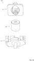
- FIGS. 2A and 2B set forth a diagram of a DC contactor with improved evacuation air pathways in accordance with at least one embodiment of the present disclosure.
- FIG. 2A illustrates a perspective view of a DC contactor 200
- FIG. 2B illustrates a component view of the DC contactor 200.
- the contactor 200 of FIG. 2A and 2B is similar to the contactor 100 of FIG. 1A and 1B in that the contactor 200 also includes components, such as a plunger tube 223, a shaft 210, a upper static core 226, a shaft assembly 224, a weld plate 220, a port 228, an arc chamber 299, an arc shield 216, and housing 298, which perform similar functions to the components of the same name in FIG.
- vent pathways 260 are added to an underside of the arc shield 216 proximate to the weld plate 220 to facilitate air flow between the underside of the arc shield 216 and the weld plate 220 to the port 228.
- the shaft assembly 224 also includes vent pathways 262 added to the underside of the shaft assembly 224 to facilitate air flow between the underside of the arc shield 216 and the weld plate 220 to the port 228.
- the upper static core 226 includes vent pathways 264 which are added to the shaft opening to facilitate air flow between the shaft 210 and the upper static core 226.
- vent pathways may be implemented as cavities, through-holes, or apertures of the arc shield, shaft assembly, and upper static core.
- the vent pathways 260 in FIG. 2B are apertures that have an opening at the top side 215 (visible in FIG. 2A and bottom side 217 (visible in FIG. 2B ) of the arc shield 216, which allow airflow through the arc shield 216.
- the vent pathways 262 underneath the shaft assembly 224 are cavities that create a space between the shaft assembly and the weld plate.
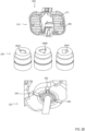
- FIG. 2B three variations of the vent pathways 264 of the upper static core 226A, 226B, 226C are illustrated.
- three through-holes are positioned on the outside of the center shaft opening of the upper static core 226 without expanding the center shaft opening.
- two through-holes are separate from and parallel to the center shaft opening of the upper static core.
- three through-holes are separate from and parallel to the center shaft opening of the upper static core.
- the circumference of the center shaft opening is not enlarged.
- a larger shaft opening in the upper static core is not desirable as it degrades position of the shaft 210 within the shaft opening.
- the vent pathways 264 allow air flow while maintaining alignment of the shaft axis with the axis of the shaft opening.
- vent pathways 260, 262, 264 facilitate air flow between the port 228, the arc chamber 299, and a cavity 296 of the plunger tube 223 for a faster and more complete evacuation. Increased vacuum results in shorter vacuum evacuation times and a lower residual amount of oxygen and water vapor in the DC contactor 200. As such, the purge process during the manufacturing process to remove oxygen and water vapor from the contactor before sealing it is shortened. Further, the vent pathways 260, 262, 264 increase the removal of oxygen and water vapor, which mitigates oxidation of the conductive copper elements and keeps the contact resistance low for the life of the product.
- an improved air pathway 297 (indicated by arrows) is created from the port 228 to under the arc shield 216 to under the shaft assembly 224 to between the shaft 210 and the upper static core 226.
- Readers of skill in the art will realize that in other embodiments, only one or more of the arc shield, the shaft assembly, or the upper static core include one or more vent pathways in the air pathways interconnecting the port, the arc chamber, and the plunger tube. After the gas is vacuum removed from the interior chambers of the DC contactor 500, the port 228 is sealed, creating a hermetically sealed enclosure for the arc chamber and the plunger tube.
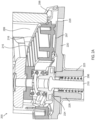
- FIG. 2C sets forth a partial view of DC contactor 200 for improving vacuum evacuation speed on DC contactors in accordance with at least one embodiment of the present disclosure.
- the weld plate is disposed on top of the upper static core.
- the upper static core 226 extends through the weld plate 220. In this way, air flow through the vent pathways 264 in the upper static core 226 is increased.
- FIG. 3 sets forth a flow chart of an example method for improving vacuum evacuation speed on DC contactors in accordance with the present disclosure.
- the method of FIG. 3 includes placing 302 an upper static core in a plunger tube, wherein the upper static core includes one or more first vent pathways.
- the upper static core may be the same as or similar to the upper static core 226 shown in FIGS. 2A to 2C .
- Placing 302 the upper static core may be carried out by inserting the upper static core into the plunger tube as shown in FIGS. 2A and 2C .
- the method of FIG. 3 also includes fixing 304 a weld plate to the plunger tube, wherein the plunger tube includes a port. Fixing 304 a weld plate to the plunger tube, wherein the plunger tube includes a port may be carried out as shown in FIGS. 2A to 2C .
- the method of FIG. 3 also includes fixing 306 a shaft assembly to a shaft, wherein the shaft assembly includes one or more second vent pathways.
- the shaft assembly may be the same as or similar to the shaft assembly 224 shown in FIGS. 2A to 2C .
- Fixing 306 a shaft assembly to a shaft, wherein the shaft assembly includes one or more second vent pathways may be carried out as shown in FIGS. 2A to 2C .
- the method of FIG. 3 also includes placing 308 an arc shield on the weld plate, wherein the arc shield includes one or more third vent pathways.
- the arc shield may be the same as or similar to the arc shield 216 shown in FIGS. 2A to 2C .
- Placing 308 an arc shield on the weld plate, wherein the arc shield includes one or more third vent pathways may be carried out as shown in FIGS. 2A to 2C .
- FIG. 4 sets forth a flow chart of an example method for improving vacuum evacuation speed on DC contactors in accordance with the present disclosure.
- the method of FIG. 4 includes connecting 402 a pump to a port of a DC contactor.
- the DC contactor includes a weld plate having a port, a housing coupled to a first side of the weld plate and defining a chamber, and a plunger tube coupled to a second side of the weld plate.
- the DC contactor also includes an upper static core disposed at least partially within the plunger tube, a shaft assembly coupled to a shaft and disposed above the upper static core, an arc shield disposed on the weld plate within the chamber, and one or more vent pathways in one or more of the arc shield, the shaft assembly, and the upper static core.
- the one or more vent pathways provide an air pathway to the port.
- the method of FIG. 4 also includes evacuating 404 gas from the interior of the DC contactor through the port.
- Evacuating 404 gas from the interior of a DC contactor through the port involves connecting a vacuum pump to the evacuation port and securely routing the gas into a recovery tank or containment system. The pump creates a vacuum, drawing the gas out while ensuring no leaks occur during the process.
- the method of FIG. 4 also includes subsequent to evacuating the gas from the interior of the DC contactor through the port, creating 406 a hermetically sealed enclosure for the arc chamber and the plunger tube by sealing the port.
- Sealing the port of the DC contactor after evacuating the gas can be achieved through various methods, depending on the design requirements and materials involved.
- the port may be sealed using a precision welding process, such as laser welding or TIG (Tungsten Inert Gas).
- TIG Tusten Inert Gas
- a soldering or brazing material may be melted and applied to the port to form a seal.
- high-strength, airtight epoxy or adhesive is applied to seal the port.
- a specialized plug or cap may be inserted into the port and mechanically fastened (e.g., by crimping or threading) or adhered using a sealing material.
- a glass-to-metal seal may be used, where a glass material is melted and bonded to the metal port, creating an airtight and hermetic seal.
- a crimping process may be used to mechanically compress a metal collar or seal around the port opening.
- FIG. 5 sets forth a flow chart of an example method for manufacturing a DC contactor with improved evacuation air pathways in accordance with the present disclosure.
- the method of FIG. 5 includes incorporating 502 an upper static core at least partially within a plunger tube.
- the upper static core may be the same as or similar to the upper static core 226 shown in FIGS. 2A to 2C and the plunger tube may be the same as or similar to the plunger tube 223 shown in FIGs. 2A to 2C .
- Incorporating 502 an upper static core at least partially within a plunger tube may be carried out by inserting the upper static core into the plunger tube as shown in FIGS. 2A to 2C .
- the method of FIG. 5 also includes coupling 504 the plunger tube to a weld plate having a port.
- the weld plate may be the same as or similar to the weld plate 220 shown in FIGS. 2A to 2C .
- Coupling 504 the plunger tube to a weld plate having a port may be carried out by welding the plunger tube to the weld plate.
- the method of FIG. 5 also includes coupling 506 a shaft assembly to the weld plate such that a shaft of the shaft assembly is disposed within the upper static core.
- the shaft assembly may be the same as or similar to the shaft assembly 224 shown in FIGS. 2A to 2C .
- Coupling 506 a shaft assembly to the weld plate such that a shaft of the shaft assembly is disposed within the upper static core may be carried out by welding the shaft assembly to the weld plate.
- the method of FIG. 5 also includes forming 508 an arc chamber around the weld plate such that a cavity of the plunger tube is interconnected to the port and the arc chamber by air pathways.
- the arc chamber may be the same as or similar to the arc chamber 299 shown in FIGS. 2A to 2C .
- Forming 508 an arc chamber around the weld plate such that a cavity of the plunger tube is interconnected to the port and the arc chamber by air pathways may be carried out by welding the housing to the weld plate.
- the method of FIG. 5 also includes positioning 510 an arc shield within the arc chamber.
- the arc shield may be the same as or similar to the arc shield 216 shown in FIGS. 2A to 2C .
- Positioning 510 an arc shield within the arc chamber may be carried out by aligning the arc shield around the shaft assembly and above the weld plate.
- At least one of the arc shield, the shaft assembly, or the upper static core include one or more vent pathways positioned within the air pathways interconnecting the port, the arc chamber, and the plunger tube.
- FIG. 6 sets forth a flow chart of an example method for manufacturing a DC contactor with improved evacuation air pathways in accordance with the present disclosure.
- the method of FIG. 6 is similar to the method of FIG. in that the method of FIG. 6 includes all of the elements of FIG. 5 .
- the method of FIG. 6 also includes connecting 602 a pump to the port.
- a suitable pump for evacuating air and water from DC contactor chambers may be a two-stage rotary vane vacuum pump with the capability to handle both gas and small amounts of vapor. This type of pump is effective for applications requiring rapid evacuation and low pressure, as it creates a strong vacuum that can efficiently remove air and moisture from enclosed spaces.
- Connecting 602 a pump to the port may be carried out by coupling one end of a hose to the port and the other end of the hose to the intake of the pump.
- the method of FIG. 6 also includes evacuating 604 gas from an interior of the DC contactor through the port.
- Evacuating 604 gas from an interior of the DC contactor through the port may be carried out by turning on the pump and pumping gas out of the DC contactor through the port.
- improving vacuum evacuation speed on DC contactors include providing vent pathways to facilitate air flow between a port in weld plate of or other exterior surface DC contactor and the arc chamber and the plunger tube for a faster and more complete evacuation.
- Increased vacuum results in shorter vacuum evacuation times and a lower residual amount of oxygen and water vapor in the DC contactor.
- the purge process during the manufacturing process to remove oxygen and water vapor from the contactor before sealing it is shortened.
- the vent pathways increase the removal of oxygen and water vapor, which mitigates oxidation of the conductive copper elements and keeps the contact resistance low for the life of the product.
Landscapes
- Engineering & Computer Science (AREA)
- Manufacturing & Machinery (AREA)
- Physics & Mathematics (AREA)
- Electromagnetism (AREA)
- Contacts (AREA)
Applications Claiming Priority (1)
| Application Number | Priority Date | Filing Date | Title |
|---|---|---|---|
| US202363601466P | 2023-11-21 | 2023-11-21 |
Publications (1)
| Publication Number | Publication Date |
|---|---|
| EP4560678A1 true EP4560678A1 (fr) | 2025-05-28 |
Family
ID=93648612
Family Applications (1)
| Application Number | Title | Priority Date | Filing Date |
|---|---|---|---|
| EP24214626.4A Pending EP4560678A1 (fr) | 2023-11-21 | 2024-11-21 | Contacteurs à courant continu à voies d'évacuation d'air améliorées |
Country Status (3)
| Country | Link |
|---|---|
| US (1) | US20250166950A1 (fr) |
| EP (1) | EP4560678A1 (fr) |
| CN (1) | CN120033033A (fr) |
Citations (6)
| Publication number | Priority date | Publication date | Assignee | Title |
|---|---|---|---|---|
| CN102568933A (zh) * | 2010-10-15 | 2012-07-11 | Ls产电株式会社 | 用于制造电磁开关的装置和方法 |
| CN106783405A (zh) * | 2017-01-21 | 2017-05-31 | 上海旭光真空科技有限公司 | 一种高压直流接触器的生产方法 |
| DE102016201209B4 (de) * | 2016-01-27 | 2018-10-25 | Bayerische Motoren Werke Aktiengesellschaft | Starterrelais für ein Kraftfahrzeug mit verbessertem Druckausgleich und Ritzelstarter mit einem solchen Starterrelais |
| WO2018196547A1 (fr) * | 2017-04-28 | 2018-11-01 | 比亚迪股份有限公司 | Relais |
| US10153117B2 (en) * | 2014-08-01 | 2018-12-11 | Valeo Equipements Electriques Moteur | Electromagnetic power contactor provided with control rod having stop |
| JP2020087538A (ja) * | 2018-11-16 | 2020-06-04 | オムロン株式会社 | リレー |
-
2024
- 2024-11-18 US US18/951,602 patent/US20250166950A1/en active Pending
- 2024-11-21 CN CN202411673365.0A patent/CN120033033A/zh active Pending
- 2024-11-21 EP EP24214626.4A patent/EP4560678A1/fr active Pending
Patent Citations (6)
| Publication number | Priority date | Publication date | Assignee | Title |
|---|---|---|---|---|
| CN102568933A (zh) * | 2010-10-15 | 2012-07-11 | Ls产电株式会社 | 用于制造电磁开关的装置和方法 |
| US10153117B2 (en) * | 2014-08-01 | 2018-12-11 | Valeo Equipements Electriques Moteur | Electromagnetic power contactor provided with control rod having stop |
| DE102016201209B4 (de) * | 2016-01-27 | 2018-10-25 | Bayerische Motoren Werke Aktiengesellschaft | Starterrelais für ein Kraftfahrzeug mit verbessertem Druckausgleich und Ritzelstarter mit einem solchen Starterrelais |
| CN106783405A (zh) * | 2017-01-21 | 2017-05-31 | 上海旭光真空科技有限公司 | 一种高压直流接触器的生产方法 |
| WO2018196547A1 (fr) * | 2017-04-28 | 2018-11-01 | 比亚迪股份有限公司 | Relais |
| JP2020087538A (ja) * | 2018-11-16 | 2020-06-04 | オムロン株式会社 | リレー |
Also Published As
| Publication number | Publication date |
|---|---|
| CN120033033A (zh) | 2025-05-23 |
| US20250166950A1 (en) | 2025-05-22 |
Similar Documents
| Publication | Publication Date | Title |
|---|---|---|
| CN100468589C (zh) | 开关装置 | |
| US20150187518A1 (en) | Sectionalized contact contactor | |
| CN1290134C (zh) | 开关装置 | |
| US7868720B2 (en) | Hermetically sealed relay | |
| EP0249864A2 (fr) | Relais piézo-électriques en boîtiers étanches | |
| US9013254B2 (en) | Hermetically sealed manual disconnect | |
| JP2005512292A (ja) | 低電圧パワー・サーキット・ブレーカ用の電極及びそれに関連するサーキット・ブレーカ | |
| CN103377856A (zh) | 电磁继电器 | |
| CN106463291A (zh) | 触点装置 | |
| CN117832016A (zh) | 触点装置 | |
| CN1382297A (zh) | 电磁继电器 | |
| US20250166950A1 (en) | Direct current contactors with improved evacuation air pathways | |
| US5014027A (en) | Electromagnetic contactor | |
| CN106683947B (zh) | 一种直流接触器 | |
| CN221304539U (zh) | 推杆组件及继电器 | |
| US3411118A (en) | Vacuum relay with improved armature mounting and movable contact | |
| KR20170004685A (ko) | 이차전지 셀의 단락 테스트용 지그장치 | |
| CN121096815B (zh) | 高压直流接触器 | |
| CN218038934U (zh) | 一种高效灭弧高压直流继电器及其高效灭弧装置 | |
| WO2024193853A1 (fr) | Commutateur destiné à être utilisé dans un disjoncteur hybride | |
| CN222300575U (zh) | 辅助触点机构及包含该机构的继电器 | |
| GB2628435A (en) | Switch for use in a hybrid circuit breaker | |
| US20260004984A1 (en) | Electromagnetic relay | |
| EP4629275A1 (fr) | Relais | |
| JP4521815B2 (ja) | 電磁リレー |
Legal Events
| Date | Code | Title | Description |
|---|---|---|---|
| PUAI | Public reference made under article 153(3) epc to a published international application that has entered the european phase |
Free format text: ORIGINAL CODE: 0009012 |
|
| STAA | Information on the status of an ep patent application or granted ep patent |
Free format text: STATUS: THE APPLICATION HAS BEEN PUBLISHED |
|
| AK | Designated contracting states |
Kind code of ref document: A1 Designated state(s): AL AT BE BG CH CY CZ DE DK EE ES FI FR GB GR HR HU IE IS IT LI LT LU LV MC ME MK MT NL NO PL PT RO RS SE SI SK SM TR |
|
| STAA | Information on the status of an ep patent application or granted ep patent |
Free format text: STATUS: REQUEST FOR EXAMINATION WAS MADE |
|
| 17P | Request for examination filed |
Effective date: 20251125 |