EP4560680A1 - Commutateur à courant élevé et procédé de fonctionnement du commutateur à courant élevé - Google Patents
Commutateur à courant élevé et procédé de fonctionnement du commutateur à courant élevé Download PDFInfo
- Publication number
- EP4560680A1 EP4560680A1 EP23398025.9A EP23398025A EP4560680A1 EP 4560680 A1 EP4560680 A1 EP 4560680A1 EP 23398025 A EP23398025 A EP 23398025A EP 4560680 A1 EP4560680 A1 EP 4560680A1
- Authority
- EP
- European Patent Office
- Prior art keywords
- bridge element
- current switch
- contact
- intermediate position
- permanent magnet
- Prior art date
- Legal status (The legal status is an assumption and is not a legal conclusion. Google has not performed a legal analysis and makes no representation as to the accuracy of the status listed.)
- Pending
Links
Images





Classifications
-
- H—ELECTRICITY
- H01—ELECTRIC ELEMENTS
- H01H—ELECTRIC SWITCHES; RELAYS; SELECTORS; EMERGENCY PROTECTIVE DEVICES
- H01H50/00—Details of electromagnetic relays
- H01H50/16—Magnetic circuit arrangements
- H01H50/18—Movable parts of magnetic circuits, e.g. armature
- H01H50/30—Mechanical arrangements for preventing or damping vibration or shock, e.g. by balancing of armature
-
- H—ELECTRICITY
- H01—ELECTRIC ELEMENTS
- H01H—ELECTRIC SWITCHES; RELAYS; SELECTORS; EMERGENCY PROTECTIVE DEVICES
- H01H50/00—Details of electromagnetic relays
- H01H50/64—Driving arrangements between movable part of magnetic circuit and contact
- H01H50/645—Driving arrangements between movable part of magnetic circuit and contact intermediate part making a resilient or flexible connection
-
- H—ELECTRICITY
- H01—ELECTRIC ELEMENTS
- H01H—ELECTRIC SWITCHES; RELAYS; SELECTORS; EMERGENCY PROTECTIVE DEVICES
- H01H50/00—Details of electromagnetic relays
- H01H50/02—Bases; Casings; Covers
- H01H50/04—Mounting complete relay or separate parts of relay on a base or inside a case
- H01H50/041—Details concerning assembly of relays
- H01H50/045—Details particular to contactors
-
- H—ELECTRICITY
- H01—ELECTRIC ELEMENTS
- H01H—ELECTRIC SWITCHES; RELAYS; SELECTORS; EMERGENCY PROTECTIVE DEVICES
- H01H50/00—Details of electromagnetic relays
- H01H50/16—Magnetic circuit arrangements
-
- H—ELECTRICITY
- H01—ELECTRIC ELEMENTS
- H01H—ELECTRIC SWITCHES; RELAYS; SELECTORS; EMERGENCY PROTECTIVE DEVICES
- H01H50/00—Details of electromagnetic relays
- H01H50/44—Magnetic coils or windings
-
- H—ELECTRICITY
- H01—ELECTRIC ELEMENTS
- H01H—ELECTRIC SWITCHES; RELAYS; SELECTORS; EMERGENCY PROTECTIVE DEVICES
- H01H50/00—Details of electromagnetic relays
- H01H50/54—Contact arrangements
-
- H—ELECTRICITY
- H01—ELECTRIC ELEMENTS
- H01H—ELECTRIC SWITCHES; RELAYS; SELECTORS; EMERGENCY PROTECTIVE DEVICES
- H01H1/00—Contacts
- H01H1/50—Means for increasing contact pressure, preventing vibration of contacts, holding contacts together after engagement, or biasing contacts to the open position
- H01H1/54—Means for increasing contact pressure, preventing vibration of contacts, holding contacts together after engagement, or biasing contacts to the open position by magnetic force
-
- H—ELECTRICITY
- H01—ELECTRIC ELEMENTS
- H01H—ELECTRIC SWITCHES; RELAYS; SELECTORS; EMERGENCY PROTECTIVE DEVICES
- H01H50/00—Details of electromagnetic relays
- H01H50/16—Magnetic circuit arrangements
- H01H50/18—Movable parts of magnetic circuits, e.g. armature
- H01H50/20—Movable parts of magnetic circuits, e.g. armature movable inside coil and substantially lengthwise with respect to axis thereof; movable coaxially with respect to coil
-
- H—ELECTRICITY
- H01—ELECTRIC ELEMENTS
- H01H—ELECTRIC SWITCHES; RELAYS; SELECTORS; EMERGENCY PROTECTIVE DEVICES
- H01H50/00—Details of electromagnetic relays
- H01H50/54—Contact arrangements
- H01H50/546—Contact arrangements for contactors having bridging contacts
Definitions
- the invention relates to a high-current switch according to Claim 1 and to a method for operating the high-current switch according to Claim 12.
- a high-current switch is known from GB 2 347 270 A .
- an improved high-current switch in particular a contactor, in particular a bridge contactor
- the high-current switch has a housing, a braking device, an electrical switching device having a bridge element, a first switching contact and a second switching contact arranged offset from the first switching contact.
- the bridge element is movable along a lifting axis between an open position, an intermediate position and a contact position in the housing. In the contact position of the bridge element, the bridge element contacts the first switching contact and the second switching contact and electrically connects them to each other.
- the bridge element In the open position and in the intermediate position of the bridge element, the bridge element is arranged spaced apart from the first switching contact and second switching contact, and the first and second switching contacts are electrically isolated from each other.
- the intermediate position is arranged between the open position and the contact position with respect to the lifting axis.
- the braking device has a holding unit, which is operatively connected in the intermediate position to the bridge element by means of an operative connection and provides a braking force, which acts on the bridge element.
- the holding unit can be operatively connected here directly or indirectly to the bridge element.
- the operative connection between the holding unit and the bridge element is reduced, wherein, during a movement of the bridge element from the open position in the direction of the contact position, in the intermediate position of the holding unit, the braking force acts along the lifting axis counter to the movement of the bridge element.
- This configuration has the advantage that, when an acceleration acting, for example, along the lifting axis, is introduced into the high-current switch, the bridge element is prevented by the braking device from moving unintentionally into the contact position and, in the process, contacting the first and second switching contacts.
- the electrical energy store is configured, for example, as a high-voltage system, for example with an operating voltage of 800 volts, this would lead to an electrical short circuit within the electrical energy store when the high-current switch is configured to guide the bridge contactor.
- the holding unit has a permanent magnet, wherein the permanent magnet provides a magnetic field, wherein, in the intermediate position, the permanent magnet provides the operative connection.
- the switching device has a coil device and an armature arranged on the coil device, wherein the armature is mechanically connected to the bridge element.
- the coil device When the coil device is energized with an electric current, the coil device is configured to move the armature along the lifting axis in such a manner that the armature moves the bridge element between the open position via the intermediate position into the contact position.
- the switching device has a sleeve which extends along the lifting axis, wherein the armature is arranged at least in sections in the sleeve, wherein the sleeve on a side facing the permanent magnet has a stop surface arranged at an inclination with respect to the lifting axis, wherein the permanent magnet has a second end face and the armature on a side facing the permanent magnet has an armature end surface, wherein, in the open position, the permanent magnet lies against the armature end face and is arranged spaced apart from the stop surface, wherein, in the intermediate position, the permanent magnet lies against the stop surface and couples the armature magnetically to the sleeve and generates the braking force
- This configuration has the advantage that the bridge element can be held particularly stably in the intermediate position.
- the braking device has a plunger which extends along the lifting axis and is arranged movably in the housing along the lifting axis independently of the bridge element, wherein, in the open position, the plunger is arranged spaced apart from the bridge element, wherein, during a movement of the bridge element from the open position in the direction of the contact position in the intermediate position, the bridge element contacts the plunger in order to form the operative connection.
- This configuration has the advantage that the plunger is particularly simple. Furthermore, a particularly high braking force is ensured by the arrangement of the plunger portion in the effective range of the magnetic field, and therefore, even at great accelerations of the braking device, an unintentional movement of the bridge element into the contact position can be prevented.
- the permanent magnet secures the plunger
- the permanent magnet is annular and has a first pole and a second pole.
- the first pole is arranged on a side facing away from the bridge element and the second pole is arranged on a side facing the bridge element.
- the plunger has a plunger portion extending outwards in the radial direction and a pin which is connected to the plunger portion and extends along the lifting axis, wherein the plunger portion is arranged on a side of the pin facing away from the bridge element, wherein, in the open position and the intermediate position, the plunger portion is arranged in an effective range of the magnetic field.
- the permanent magnet has a first through-opening extending along the lifting axis, wherein the plunger reaches through the first through-opening and, on a side facing the bridge element, protrudes over the permanent magnet, wherein the plunger has a lateral surface extending around the lifting axis, wherein a first radial gap is arranged between the lateral surface and a first inner surface of the first through-opening.
- the braking device has a coupling unit, wherein the coupling unit is connected to the housing and has a second through-opening, wherein the plunger penetrates the second through-opening at least in sections, wherein, preferably, the plunger and the second through-opening are formed corresponding to the guiding of the plunger along the lifting axis.
- this configuration has the advantage that the magnetic field can be introduced in a targeted manner into the plunger by means of the coupling unit in the open and intermediate positions. Furthermore, in the contact position or on a path between the intermediate position and the contact position, a targeted short-circuiting of the magnetic field can be achieved by the coupling unit in connection with the plunger portion.
- the holding unit has at least one spring arrangement, wherein the plunger is connected to the spring arrangement, wherein the spring arrangement provides the braking force, wherein, during a movement of the bridge element from the intermediate position in the direction of the contact position, the spring arrangement is tensioned, wherein, preferably, the spring arrangement is pretensioned in the intermediate position, wherein, preferably, the spring arrangement has at least one spring configured in the manner of a disc spring, or a plurality of springs arranged in a stack, wherein, in the contact position, the spring arrangement is at least partially relaxed.
- the spring arrangement is mechanically particularly simple and durable and makes a particularly simply constructed high-current switch possible.
- the spring arrangement is arranged between the housing and the plunger, wherein the plunger lies against the spring arrangement and the spring arrangement acts against the plunger, wherein, during the movement of the bridge element from the open position in the direction of the contact position, the plunger between the intermediate position and the contact position tensions the spring arrangement.
- the high-current switch can be particularly readily operated in that the bridge element is moved into the open position, wherein the bridge element is moved from the open position in the direction of the contact position, in particular on the basis of an unintentional acceleration, with an actuating force along the lifting axis, wherein, at least in the intermediate position, the holding unit is operatively connected to the bridge element and the braking force acts on the bridge element along the lifting axis counter to the movement of the bridge element and the actuating force, wherein the bridge element, after overcoming the braking force, is moved from the intermediate position into the contact position and the operative connection is reduced.
- This configuration has the advantage that the braking force can be overcome by the bridge element only in the event of driving and actively switching the switching device and, when an acceleration is introduced into the bridge element, only the bridge element can move between the open position and the intermediate position.
- the permanent magnet in the open position, lies against the armature, wherein, in the intermediate position, the permanent magnet strikes with the second end face against the stop surface and operatively connects the armature magnetically to the sleeve, wherein, during a movement of the bridge element from the intermediate position into the contact position, the armature is separated from the permanent magnet.
- the braking force acting on the plunger decreases, preferably decreases degressively.
- the disc spring like the magnetic arrangement, also provides a degressive force progression from the intermediate position to the contact position such that, after the braking force is overcome, the actuating force acting on the armature braking device by means of the braking device is less than the actual braking force.
- Figure 1 shows a longitudinal section through a high-current switch 10 according to a first embodiment.
- the high-current switch 10 can, for example, be configured as a contactor, in particular as a bridge contactor, for an electrical energy store of an electrically driven vehicle, in particular a fully electric vehicle.
- the high-current switch 10 can be used in particular in a high-voltage system, for example in an 800 volt system, to connect two battery packs, each having a pack output voltage of, for example, 400 volts, in series or parallel.
- the high-current switch 10 in its function as a bridge contactor can be connected in such a way that the high-current switch 10 is closed when charging at a 400 volt charging station, while in normal operation of the electric vehicle, the high-current switch 10 is opened such that the battery packs are connected in series and an output voltage of the electrical energy store in normal operation is a sum of the pack output voltages.
- the high-current switch 10 in its function as a bridge contactor is not unintentionally closed, for example due to sharp accelerations. This would result in a short circuit within the electrical energy store with corresponding consequences, especially with a high fire risk when using lithium ion cells. Unintentional closing of the high-current switch 10 therefore has to be avoided.
- the high-current switch 10 in a different position or with a different function.
- the high-current switch 10 is used, for example, as a central contactor and the two battery packs mentioned above are connected in series in normal operation of the vehicle.
- the high-current switch 10 is configured to transmit at least 100 amperes to 1000 amperes. In particular, the high-current switch 10 can transmit 150 amperes to 300 amperes.
- the high-current switch 10 shown by way of example in Figure 1 has, for example, a housing 15, a braking device 20, an electrical switching device 25 having a switching bridge, a connection terminal 30, a first switching contact 40 and a second switching contact 45.
- the connection terminal 30 has a first terminal connection 50 and a second terminal connection 55, the connection terminal 30 enabling the high-current switch 10 to be integrated in a high-voltage system of the electric vehicle.
- the first terminal connection 50 is arranged, for example, on the first switching contact 40 and electrically connected to the first switching contact 40.
- the second terminal connection 55 is electrically and mechanically connected to the second switching contact 45.
- the housing 15 encloses a housing interior 65, wherein the switching device 25, the braking device 20 and the first and second switching contacts 40, 45 and the bridge element 35 are arranged in the housing interior 65.
- the housing 15 is produced from an electrically non-conductive material and electrically insulates the switching contacts 40, 45 and the first terminal connection 50 from the second terminal connection 55.
- the connection terminal 30 is arranged, for example, on the outside of the housing 15 and serves for the electrical connection of the high-current switch 10 to other components of the high-voltage system.
- the bridge element 35 is movably arranged along a lifting axis 60 between an open position (shown in Figure 1 with a solid line) via an intermediate position and a contact position different from the open position (shown in Figure 1 by a dashed line).
- the intermediate position is arranged in the axial direction with respect to the lifting axis 60 between the open position and the contact position.
- the bridge element 35 extends, for example, radially outwards with respect to the lifting axis 60.
- the first switching contact 40 and the second switching contact 45 are arranged spaced apart from each other and offset from each other in the radial direction with respect to the lifting axis 60.
- the housing 15 and thus the high-current switch 10 are aligned in the electric vehicle via fastening tabs 71 of the housing 15 defined in the vehicle.
- the lifting axis 60 can be aligned in the direction of gravity.
- connection terminal 30 is arranged by way of example on the top side of the housing 15 and the switching device 25 on the bottom side in the housing 15.
- the housing 15 has a first receptacle 70 on the inner side.
- the first receptacle 70 is arranged, for example, centred on the lifting axis 60 and can have, for example, a circular cross section.
- the first receptacle 70 has a receptacle opening 75 and a first receptacle base 80.
- the first receptacle base 80 is arranged on a side facing away from the switching device 25 and the bridge element 35 in the axial direction with respect to the lifting axis 60.
- the receiving opening 75 faces the bridge element 35 axially.
- the first receptacle 70 is open at the receptacle opening 75.
- the braking device 20 is arranged at least in sections in the first receptacle 70.
- the bridge element 35 In the open position, the bridge element 35 is spaced apart, preferably at a maximum axial distance from a respective contact surface of the first and second switching contacts 40, 45, said contact surface facing the bridge element 35.
- the switching device 25 is, for example, mechanically connected to the bridge element 35 and is configured to move the bridge element 35 between the open position and the contact position in the axial direction along the lifting axis 60. It has to be ensured that the contact position is reached only when the switching device 25 is actively actuated, for example energized. In particular, an unintentional contacting of the bridge element 35 at the first switching contact 40 and the second switching contact 45 with the switching device 25 deactivated has to be avoided. Even at a high acceleration of, for example, 90 g along the lifting axis 60 acting on the bridge element 35, the contacting of the first and second switching contacts 40, 45 by the bridge element 35 should be prevented.
- the switching device 25 can have a restoring unit 85, for example with a restoring spring, which is in the open position of the bridge element 35 in a relieved state.
- the restoring unit 85 is configured, for example, to return the bridge element 35 into the open position and/or to hold it in the open position. In particular when the switching device 25 is deactivated, the restoring unit 85 moves the bridge element 35 into the open position.
- the bridge element 35 contacts both the first switching contact 40 and the second switching contact 45 on the side facing the bridge element 35 and electrically connects the first switching contact 40 to the second switching contact 45.
- the bridge element 35 can be manufactured, for example, in an annular or plate-like form, from a metallic material.
- an electrically conductive coating for example comprising silver, can be provided on contact surfaces of the bridge element 35 and/or of the respectively associated switching contact 40, 45.
- the switching device 25 further has, in addition to the restoring unit 85, a coil device 250 and an armature 255 which is surrounded by the coil device 250 and is mechanically connected, for example, to the restoring unit 85 and via a connecting means 260 to the bridge element 35.
- the connecting means can have a connecting bolt 630 and an overlift spring 635, wherein the connecting bolt 630 is connected to the armature 255 on one side.
- the connecting bolt is connected to the bridge element 35 via the overlift spring 635.
- the overlift spring 635 mechanically connects the bridge element 35 to the connecting bolt 630 to move the bridge element 35 between the open position and the contact position.
- the coil device 250 has one or more electric coils which are configured to generate a further electromagnetic field acting on the armature 255 in order to move the bridge element 35 between the open position and the contact position by an axial displacement of the armature 255.
- the configuration of the switching device 25 is selected, for example, in such a way that the contact position is maintained exclusively when the coil device 250 is energized and, if the coil device 250 is energized only slightly, if at all, the electromagnetic field is too weak to keep the bridge element 35 in the contact position.
- the restoring unit 85 causes an automatic return of the bridge element 35 and thus also of the armature 255 coupled to the bridge element 35 into the open position such that, in the event of insufficient energization, if any at all, of the coil device 250, the high-current switch 10 is opened.
- Figure 2 shows a perspective illustration of the longitudinal section shown in Figure 1 through the high-current switch 10.
- the bridge element 35 may have a plate-like basic shape.
- the bridge element 35 has a second receptacle 95 on a first end face 90 facing the braking device 20.
- the second receptacle 95 is arranged, for example, as a depression in the bridge element 35.
- the second receptacle 95 may be arranged spaced apart from a first outer circumferential side 100 of the bridge element 35. Axially, the second receptacle 95 is aligned with the first receptacle 70 and with the braking device 20.
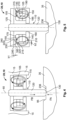
- Figure 3 shows an enlarged illustration, marked with the letter H in Figure 1 , of the braking device 20 in the open position of the bridge element 20 shown in Figures 1 and 2 .
- the braking device 20 has a holding unit 600 with a permanent magnet 105 and a plunger 110.
- the braking device 20 may furthermore have a coupling unit 115.
- the coupling unit 115 is arranged in the first receptacle 70 of the housing 15 and is mechanically connected to the housing 15.
- the permanent magnet 105 is mechanically connected to the coupling unit 115 and thus indirectly via the coupling unit 115 to the housing 15.
- the plunger 110 is arranged axially displaceably along the lifting axis 60 relative to the coupling unit 115 and to the permanent magnet 105 and also relative to the bridge element 35 and thus independently of the bridge element 35.
- the plunger 110 has, by way of example, a cylindrical pin 120 and a plunger portion 125.
- the pin 120 has a first stop surface 130 on a first end facing the bridge element 35.
- the first stop surface 130 may be formed obtusely on the pin 120 and extends, for example, at an inclination, in particular perpendicularly, to the lifting axis 60.
- the pin 120 furthermore has a lateral surface 135.
- the pin 120 may be manufactured, for example, from a paramagnetic material or a diamagnetic material.
- the plunger portion 125 On a second end of the pin 120 facing away from the first stop surface 130 and thus the bridge member 35, the plunger portion 125 is arranged on the pin 120 and mechanically connected to the pin 120.
- the plunger portion 125 may, for example, be annular.
- the plunger portion 125 protrudes over the pin 120 in the radial direction with respect to the pin 120.
- the plunger portion 125 preferably comprises a ferromagnetic material.
- the permanent magnet 105 provides a magnetic field 140.
- the magnetic field 140 is indicated schematically in Figure 3 by means of field lines.
- the permanent magnet 105 has, for example, a first pole 145, for example a north pole N, and a second pole 150, for example a south pole S.
- the first pole 145 of the permanent magnet 105 is arranged, for example, on an axial side of the permanent magnet 105 facing away from the bridge element 35 and the second pole 150 on an axial side facing the bridge element 35.
- the permanent magnet 105 has, for example, an annular configuration and extends in the circumferential direction around the lifting axis 60, for example on a circular path.
- the permanent magnet 105 has a first inner surface 175, which forms a first through-opening 176 in the permanent magnet 105.
- the pin 120 reaches through the first through-opening 176 in the axial direction and is arranged on the lifting axis 60.
- a first radial gap 180 is arranged between the first inner surface 175 and the lateral surface 135 of the pin 120. In this case, the pin 120 on the side facing the bridge element 35 protrudes over the permanent magnet 105 and the coupling unit 115.
- the coupling unit 115 has, for example, a first coupling element 155 and a second coupling element 160.
- the two coupling elements 155, 160 or even the entire coupling unit 115 may also be omitted.
- the first coupling element 155 is annular.
- the first coupling element 155 may, for example, be produced from a ferromagnetic material.
- the first coupling element 155 is arranged by way of example on an axial side of the permanent magnet 105 facing away from the bridge element 35. In this case, the first coupling element 155 can lie directly against a second end face 165 of the permanent magnet 105 and can be mechanically fastened to the permanent magnet 105.
- the first coupling element 155 has a first contact surface 170 on an axial side facing away from the bridge element 35.
- the first contact surface 170 is substantially flat and extends by way of example in a plane perpendicular to the lifting axis 60.
- the first coupling element 155 may be chamfered radially on the inside and/or radially on the outside of the first contact surface 170.
- the second coupling element 160 is by way of example pot-shaped. Of course, it would also be possible for the second coupling element 160 to have a different geometrical configuration.
- the second coupling element 160 has a first coupling element portion 185 and a second coupling element portion 190.
- the first coupling element portion 185 is substantially plate-like or annular and extends in a plane perpendicular to the lifting axis 60.
- the second coupling element portion 190 is hollow-cylindrical and extends around the lifting axis 60.
- first coupling element 155 and the permanent magnet 105 are arranged radially on the inside of the second coupling element portion 190.
- the permanent magnet 105 and/or the first coupling element 155 are arranged spaced apart radially from the second coupling element portion 190.
- the second coupling element portion 190 is connected to the first coupling element portion 185 on an axial side facing the bridge element 35.
- the first coupling element portion 185 and the second coupling element portion 190 are produced integrally from the same material, preferably from a ferromagnetic material.
- the first coupling element portion 185 which is annular by way of example, is connected in the axial direction on an axial side of the permanent magnet 105 facing the bridge element 35.
- the permanent magnet 105 is arranged on both sides in the axial direction between the first coupling element 155 and the second coupling element 160, in particular the first coupling element portion 185.
- the first coupling element portion 185 has a second through-opening 195 radially on the inside.
- the second through-opening 195 is arranged in the radial direction spaced apart from the lateral surface 135 of the pin 120 such that a second radial gap 205 is formed between a second inner surface 200 of the second through-opening 195 and the lateral surface 135, wherein the second radial gap 205 is preferably more slender in the radial direction than the first radial gap 180.
- the first coupling element portion 185 it would also be possible for the first coupling element portion 185 to have a similar width in the radial direction as the permanent magnet 105 such that the second inner surface 200 ends in the radial direction level with the first inner surface 175.
- the second coupling element portion 190 has a third inner surface 210.
- a third radial gap 220 is arranged between a second outer circumferential side 215 of the first coupling element 155 and the third inner surface 210.
- the plunger portion 125 has a second contact surface 225 on the side facing the bridge element 35.
- the first contact surface 170 and the second contact surface 225 can preferably be arranged in a plane perpendicular to the lifting axis 60. In the open position of the bridge element 35, as shown in Figure 3 , the first contact surface 170 lies against the second contact surface 225.
- the second coupling element portion 190 furthermore has a third contact surface 230.
- the first contact surface 170 and the third contact surface 230 are preferably arranged in a common plane, preferably perpendicular to the lifting axis 60. In the open position, as shown in Figure 3 , the plunger portion 125 lies with the second contact surface 225 against the first contact surface 170 and the third contact surface 230.
- the permanent magnet 105 provides the magnetic field 140.
- the magnetic field 140 is indicated schematically in Figure 3 by way of example by means of magnetic field lines.
- a magnetic flux of the magnetic field 140 is closed.
- the magnetic flux of the permanent magnet 105 into the plunger portion 125 takes place, for example, on the end face on the side facing away from the bridge element 35 from the first pole 145 via the first coupling element 155 and the contact between the first and second contact surfaces 170, 225.
- the plunger portion 125 is magnetically operatively connected to the permanent magnet 105, and the permanent magnet 105 holds the plunger portion against the first coupling element 155 via the magnetic field 140.
- the first radial gap 180 and the second radial gap 205 between the permanent magnet 105 and the first coupling element portion 185 have the effect that the magnetic field 140 essentially does not act on the pin 120, and instead the coupling of the plunger 110 substantially takes place via the plunger portion 125. Furthermore, a magnetic short circuit between the permanent magnet 105 and the second coupling element portion 190 is prevented by the third radial gap 220 and by the radially spaced-apart arrangement of the permanent magnet 105 from the third inner surface 210.
- Figure 4 shows a schematic illustration of the braking device 20 in the intermediate position of the bridge element 35.
- the braking device 20 In the intermediate position of the bridge element 35, the braking device 20 has the same arrangement of the components with respect to one another as in the open position of the bridge element 35. Therefore, only the differences of the high-current switch 10 when the bridge element 35 is in the intermediate position compared to the open position will be discussed.
- the pin 120 lies with the first stop surface 130 against the second receiving base 236 of the second receptacle 95.
- the intermediate position of the bridge element 35 is preferably arranged in the axial direction with respect to the lifting axis 60 between the contact position and the open position (cf. Figure 3 ). In the intermediate position, the bridge element 35 comes into touching contact with the first stop surface 130, but does not contact the first and second switching contacts 40, 45, and therefore the high-current switch 10 is also open in the intermediate position.
- the plunger 110 is magnetically connected to the housing 15 by the permanent magnet 105 via the coupling unit 115 and the permanent magnet 105. In the intermediate position, the permanent magnet 105 prevents axial displaceability of the pin 120 relative to the housing 15.
- Figure 5 shows the braking device 20 of the high-current switch 10 in the contact position of the bridge element 35.
- the bridge element 35 In the open position of the bridge element 35, the bridge element 35 lies with the second receiving base 236 against the first stop surface 130. Furthermore, radially on the outside of the second receptacle 95, the bridge element 35 contacts both the first switching contact 40 and the second switching contact 45 and connects the first switching contact 40 to the second switching contact 45 (not shown in Figure 5 ).
- the high-current switch 10 is thus closed in the contact position of the bridge element 35 and the high current can flow via the first terminal connection 50 and the first switching contact 40 via the bridge element 35 to the second switching contact 45 and from the second switching contact 45 to the second terminal connection 55.
- a second axial gap 245 is formed between the first contact surface 170 and the third contact surface 230, the second axial gap having, for example, the same axial first gap width b1 as the first axial gap 240.
- the first axial gap 240 and the second axial gap 245 are wider in the axial direction than a second gap width b2 in the radial direction of the third radial gap 220.
- This configuration has the advantage that the magnetic field 140 is short-circuited by the first coupling element 155 in the contact position and the plunger portion 125 is arranged outside an effective range of the magnetic field 140.
- the magnetic field 140 exits from the permanent magnet 105 at the first pole 145, for example, and is guided through the first coupling element 155 to the third radial gap 220.
- the magnetic field 140 exits from the first coupling element 155 radially on the outside of the second outer circumferential side 215 and passes through the third radial gap 220 between the first coupling element 155 and the second coupling element portion 190.
- the magnetic field 140 enters the second coupling element portion 190 and is guided by the second coupling element portion 190 in the direction of the bridge element 35. From the second coupling element portion 190, the magnetic field 140 enters the first coupling element portion 185 and is guided from the first coupling element portion 185 towards the second pole 150 of the permanent magnet 105 such that the magnetic field 140 is closed.
- the magnetic field 140 is guided in the contact position substantially exclusively in the coupling unit 115 and the permanent magnet 105, and the plunger portion 125 and/or the pin 120 are arranged outside an effective range of the magnetic field 140.
- the plunger 110 is substantially decoupled from the permanent magnet 105 and the magnetic field 140 is short-circuited via the coupling unit 115.
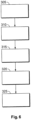
- Figure 6 shows a flow diagram of a method for operating the high-current switch 10 shown in Figures 1 to 5 .
- Figure 7 shows a diagram of an actuating force FA plotted over a travel distance D of the armature 255 for the movement of the bridge element 35 between the open position OP and the contact position KP for transferring the bridge element 35 from the open position OP into the contact position.
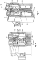
- Figure 8 shows a perspective sectional view of the high-current switch 10 shown in Figures 1 to 5 , in which the bridge element 35 is in the intermediate position.
- Figure 9 shows a perspective sectional view through the high-current switch 10 shown in Figures 1 to 5 , in which the bridge element 35 is in the contact position.
- the diagram shown in Figure 7 shows a first graph 500.
- the first graph 500 shows the progression of the actuating force FA over the travel distance D between the open position OP and the contact position KP.
- the open position OP is located at the right end of the abscissa.
- the actuating force FA is provided by a corresponding energization of the coil device 250 of the switching device 25.
- the actuating force FA shown is applied to the armature 255.
- the armature 255 has the greatest travel distance D, which decreases as the bridge element 35 draws closer to the contact position.
- the first graph 500 has a first graph section 501, a second graph section 502, a third graph section 503 and at least one fourth graph section 504.
- the high-current switch 10 is provided with the bridge element 35 in the open position.
- energization of the coil device 250 is interrupted, and therefore the restoring unit 85 may move the bridge element 35 into the open position and the armature 255 into a starting position.
- the high-current switch 10 is open and a power transmission between the terminal connections 50, 55 is interrupted.
- a second method step 310 the coil device 250 is energized.
- the coil device 250 generates the electromagnetic field which acts on the armature 255 with an actuating force FA.
- the armature 255 is moved in the axial direction along the lifting axis 60 by the actuating force FA and, in the process, actuates the restoring unit 85.
- the restoring unit 85 is tensioned by the armature 255 and provides a restoring force FR (cf. Figure 1 ).
- the restoring force FR acts counter to the actuating force FA.
- the bridge element 35 is moved from the open position in the direction of the contact position along the lifting axis 60 counter to the effect of the restoring force FR.
- the restoring unit 85 is tensioned by the actuating force FA as the travel distance D decreases in the first graph section 502.
- the actuating force FA can also act on the armature 255 by means of an acceleration.
- the acceleration may be of such a magnitude that the actuating force FA induced by the acceleration in the armature is greater than the restoring force FR.
- a third method step 315 the pin 120 protruding via the receiving opening 75 into the housing interior 65 enters at the first stop surface 130 into touching contact with the second receiving base 236 of the second receptacle 95.
- the bridge element 35 is located in the intermediate position ZP (cf. Figure 4 ).
- the braking device 20 By means of the magnetic coupling of the plunger 110 to the permanent magnet 105, preferably via the coupling unit 115, the braking device 20 provides a braking force FB, which acts along the lifting axis 60 in the opposite direction to the actuating force FA (cf. Figure 4 ).
- the braking force FB prevents the bridge element 35 from moving further in the direction of the contact position.
- the braking force FB together with the restoring force FR, thus increases the necessary actuating force FA for moving the bridge element 35 from intermediate position ZP in the direction of the contact position. Since the braking force FB and the restoring force FR both act counter to the actuating force FA, a gradient of the first graph 500 in the second graph section 502 is significantly steeper than in the first graph section 501 (cf. Figure 7 ).
- the switching device 25 displaces the bridge element 35 further in the direction of the contact position KP (cf. Figure 5 ).
- the bridge element 35 carries along the plunger 110 with it.
- the plunger portion 125 is moved away from the first and third contact surfaces 170, 230 in the axial direction.
- the braking force FB greatly decreases as the formation of the first and second axial gaps 240, 245 increases in the third graph section 503, and therefore the switching device 25 is no longer prevented by the braking force FB from moving the bridge element 35 out of the intermediate position in the direction of the contact position.
- the braking force FB in the intermediate position ZP is preferably significantly greater than the restoring force FR, it is ensured that, when the actuating force FA is generated by an acceleration, the actuating force FA is less than the sum of the restoring force FR and the braking force FB. In the event of sharp accelerations, this prevents further movement of the bridge element 35 beyond the intermediate position in the direction of the contact position and thus the closing of the contacts, by the bridge element 35 in the intermediate position striking against the pin.
- a fourth method step 320 the bridge element 35 enters into touching contact with the first and second switching contacts 40, 45 and connects the first switching contact 40 electrically to the second switching contact 45 such that the high-current switch 10 is electrically closed.
- the restoring force FR of the restoring unit 85 substantially acts counter to the actuating force FA, and the braking force FB is substantially cancelled by the magnetic decoupling of the plunger 110 from the permanent magnet 105.
- the bridge element 35 is subjected to excessive pressure by the switching device 25.
- the armature 250 is moved further in the direction of the switching contact 40, 45 and its end position, with the overlift spring 635 in the fourth graph section 504 being tensioned.
- the rigid configuration of the overlift spring 635 and the addition of the braking force to an overlift spring force of the overlift spring 635, which acts counter to the actuating force, means that the progression of the fourth graph section 504 is steeper than in the first graph curve.
- a fifth method step 325 the energization of the coil device 250 is cancelled in order to open the high-current switch 10.
- the switching device 25 essentially does not provide any actuating force FA.
- the armature 255 is moved out of its end position in the direction of the starting position firstly by means of the overlift spring 635 and the restoring unit 85, and, from the contact position KP in the direction of the starting position, exclusively by means of the restoring unit 85.
- the restoring unit 85 substantially transfers the bridge element 35 by the restoring force FR from the contact position in the direction of the intermediate position.
- the magnetic short circuit within the braking device 20 is cancelled and the braking device 20 assists the movement of the bridge element 35 shortly before the intermediate position is reached.
- the assistance is removed by the travel achieved by the plunger 110, and from the intermediate position in the direction of the open position, the restoring unit 85 transfers the bridge element 35 into the open position by means of the restoring force FR.
- the force of the braking element to be added during the reduction of the overlift additionally accelerates the armature. This results in faster separation of the contact pieces.
- the reaching of the contact position due to unintentional accelerations should be prevented.
- This is achieved in the embodiment by the restoring unit 85 and additionally by the braking device 20 together.
- lesser accelerations for example, less than 20 g
- the restoring force FR of the restoring unit 85 which is preferably already pretensioned into the open position.
- the bridge element 35 In order to prevent the reaching of the contact position in the event of high accelerations, for example accelerations of preferably between 50 g and up to 90 g along the lifting axis 60 of the bridge element 35, the bridge element 35, which is accelerated out of the open position, on the way to the contact position along the lifting axis 60 strikes against the first stop surface 130 of the pin 120.
- the braking device 20 provides the braking force FB independently of the switching device 25 and, in the intermediate position, greatly increases the necessary actuating force FA.
- the braking force FB decelerates the already accelerated bridge element 35 and prevents the bridge element 35 from further movement out of the intermediate position ZP in the direction of the contact position KP.
- the braking device 20 is dimensioned here in such a way that, even in the event of sharp accelerations, the actuating force induced in the armature 255 is less than the minimally required actuating force FA.
- the braking device 20 has the advantage here that an easy movability of the bridge element 35 between the contact position and the intermediate position or out of the intermediate position into the contact position is ensured by the magnetic short circuit or the rapid decoupling of the plunger portion 125 from the magnetic field 140. This ensures secure contacting of the first and second switching contacts 40, 45 with a high contact force for the electrical connection and for closing the high-current switch 10.
- the magnetic braking force FB which greatly decreases over the travel distance D, ensures that the switching device 25 is not overloaded after the intermediate position ZP is exceeded and as the distance of the bridge element 35 increases, by provision of the actuating force FA. Furthermore, an increase in a spring rate for determining the restoring force FR can be dispensed with, and thus the restoring unit 85 can be configured mechanically particularly simply and compactly.
- the decoupling of the plunger portion 125 from the magnetic field 140 has the effect that, in the contact position, secure pressing of the bridge element 35 against the switching contacts 40, 45 is ensured by means of the actuating force FA.
- the braking force FB can be 10 N to 35 N, for example 0.5 to 1.5 mm, in particular 1 mm, before the contact position is reached.
- the above-described configuration of the high-current switch 10 has the advantage that the high-current switch 10 is particularly shock-resistant, in particular to accelerations along the lifting axis 60.
- the high-current switch 10 is suitable in particular as a central switch or as a bridge contactor for an electrical energy store of an electric vehicle.
- the braking device 20 can be integrated particularly simply and cost-effectively in an already existing design of a high-current switch 10.
- the braking device 20, by means of the braking force FB prevents the bridge element 35, which is moving in the direction of the contact position because of the acceleration, from a further movement out of the intermediate position in the direction of the contact position.
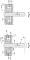
- Figure 10 shows a section of a braking device 20 of a high-current switch 10 according to a second embodiment.
- the braking device 20 of the high-current switch 10 is substantially identical to the braking device 20 shown in Figures 1 to 5 , 8 and 9 . Only the differences of the braking device 20, shown in Figure 10 , of the high-current switch 10 according to the second embodiment in relation to the braking device 20, shown in Figures 1 to 5 , 8 and 9 , of the high-current switch 10 according to the first embodiment will be discussed below.
- the coupling unit 115 is adapted in such a way that the coupling unit 115, for example, has only the first coupling element 155. Furthermore, the first coupling element 155 is arranged on the side of the permanent magnet 105 facing the bridge element 35 and, for example, is connected mechanically to the permanent magnet 105 and mechanically to the housing 15. The configuration of the first coupling element 155 can be annular.
- the plunger portion 125 is stepped.
- the plunger portion 125 is adapted to the effect that the second contact surface 225 has a first partial region 400 and a second partial region 405, wherein the first partial region 400 is axially offset with respect to the second partial region 405.
- the second contact surface 225 lies with the first partial region 400 against the permanent magnet 105 on an axial side facing away from the bridge element 35.
- the second partial region 405 arranged radially on the inside of the first partial region 400 lies against the first coupling element 155 such that, in the open position, the magnetic flux of the magnetic field 140 is closed by the first coupling element 155 and the plunger portion 125 and also by the permanent magnet 105.
- Figure 11 shows the high-current switch 10 shown in Figure 10 according to the second embodiment in the contact position of the bridge element 35.
- the plunger portion 125 In the contact position, the plunger portion 125 is axially spaced apart from the permanent magnet 105 and the first coupling element 155. In this configuration, the plunger portion 125 is not removed from the effective range of the magnetic field 140, but rather is arranged only so far from the magnetic field 140 of the permanent magnet 105 that the braking force FB generated by the magnetic field 140 is greatly attenuated compared to the open position and intermediate position shown in Figure 10 .
- the second embodiment of the high-current switch 10 shown in Figures 10 and 11 , in particular the braking device 20, has the advantage that the braking device 20 is configured particularly simply and cost-effectively.
- FIG 12 shows a section C, marked in Figure 1 , of a high-current switch 10 according to a third embodiment.
- the high-current switch 10 is substantially identical to the high-current switch 10 shown in Figure 1 according to the first embodiment. Only the differences of the high-current switch 10, shown in Figure 12 , according to the third embodiment in relation to the high-current switch 10, explained in Figure 1 , of the first embodiment will be discussed below.
- the braking device 20 is arranged with respect to the switching device 25 axially with respect to the lifting axis 60 opposite the arrangement of the braking device 20, shown in Figure 1 , in the first receptacle 70.
- the switching device 25 has a sleeve 610 next to the coil device 250 and the armature 255.
- the sleeve 610 is connected, for example, to the coil device 250.
- the sleeve 610 extends along the lifting axis 60 and surrounds the armature 255 circumferentially.
- the sleeve 610 is arranged radially outwards with respect to the armature 255.
- the restoring spring 620 is supported on the third receiving base 625. Furthermore, the connecting bolt 630 is guided in the third receptacle 615 along the lifting axis 60, said connecting bolt 630 being connected to the bridge element 35 directly or indirectly on a side facing away from the armature 255.
- the sleeve 610 has, for example, a first sleeve portion 640 and a second sleeve portion 645 axially adjoining the first sleeve portion 640 on an axial side facing the bridge element 35.
- the sleeve 610 has a first radial extent on the inside in the first sleeve portion 640 and a second radial extent on the inside in the second sleeve portion 645, wherein the second radial extent in the second sleeve portion 645 is selected to be smaller than in the first sleeve portion 640.
- the first sleeve portion 640 adjoins a sleeve end face 650, which is arranged on a side facing away from the bridge element 35.
- the sleeve 610 has a step on which the sleeve 610 has a second stop surface 655.
- the second stop surface 655 may be oriented, for example, at an inclination, preferably perpendicularly, to the lifting axis 60.
- the second stop surface 655 is arranged axially offset with respect to the sleeve end face 650 and is offset in the direction of the bridge element 35.
- the permanent magnet 105 of the braking device 20 is annular. In this case, the permanent magnet 105 is arranged on a side facing away from the bridge element 35 with respect to the switching device 25.
- the bridge element 35 is arranged in the open position, by way of example.
- the armature 255 is thus also arranged spaced apart as far as possible from the switching contacts 40, 45.
- the permanent magnet 105 of the holding unit 600 can at least partially protrude over the sleeve end face 650 and is only partially arranged in the first sleeve portion 640.
- the permanent magnet 105 lies with the second end face 165, which faces the bridge element 35 in Figure 12 , against the armature end surface 605 and, by means of the magnetic field 140 provided by the permanent magnet 105, is magnetically connected to the armature 255 by means of a magnetic force FM.
- the magnetic force FM acts counter to the actuating force FA, for example.
- the magnetic force FM secures the permanent magnet 105 on the armature 255 in the open position such that they are connected to each other with a force fit.
- the holding unit 600 can comprise the coupling unit 115 with the first coupling element 155.
- the second coupling element 160 can be omitted.
- the first coupling element 155 engages, for example, radially on the inside in the permanent magnet 105 and rests on a third end face 660 of the permanent magnet 105 facing away from the bridge element 35.
- the first coupling element 155 may also be dispensed with in the embodiment.
- the first coupling element 155 has, for example, a T-shaped configuration in cross section.
- the first coupling element 155 is formed from ferromagnetic material and is displaceable axially in relation to the armature 255.
- the permanent magnet 105 is arranged axially between the first coupling element 155 and the armature end surface 605.
- the first coupling element 155 can reach with an engagement portion 665 arranged radially on the inside through the annular permanent magnet 105 and can engage in the third receptacle 615 of the armature 255 which is also produced from ferromagnetic material.
- the magnetic field 140 of the permanent magnet 105 is guided in the open position in such a way that there is a magnetic closure between the permanent magnet 105, the armature 255 and the first coupling element 155, and the magnetic field 140 couples them to one another.
- Figure 13 shows a section E, marked in Figure 12 , of the high-current switch 10.
- the bridge element 35 is moved into the intermediate position by means of the actuating force FA.
- the armature 255 is arranged axially offset in relation to Figure 12 (offset upwards in Figure 13 ).
- the permanent magnet 105 enters into contact with the second stop surface 655 and continues to lie with the second end face 165 against the armature end surface 605.
- the magnetic coupling of the permanent magnet 105 with the armature 255 causes the permanent magnet 105 to form a type of shoulder or edge.
- Figure 14 shows a section E, shown in Figure 12 , of the high-current switch 10 in the contact position of the bridge element 35.
- the armature 255 In the contact position, the armature 255 is separated from the permanent magnet 105 such that a third axial gap 670 is present between the armature end surface 605 and the second end face 165.
- the magnetic field 140 acts only slightly, if at all, on the armature 255, and therefore the magnetic force FM is greatly reduced compared to the open position and the intermediate position.
- the magnetic force FM decreases as the distance a3 between the second end face 165 and the armature end surface 605 increases, and therefore the contact pressure force with which the armature 255 acts on the bridge element 35 is reduced only slightly, if at all, by the magnetic field 140.
- the magnetic field 140 of the permanent magnet 105 is guided between the sleeve 610 and the first coupling element 155.
- the magnetic field 140 enters the first coupling element 155 on the side facing away from the second stop surface 655, wherein the first coupling element 155 guides the magnetic field 140 back to the permanent magnet 105 such that a magnetic flux of the magnetic field 140 is closed in the contact position. This can further minimize the effect of the magnetic field 140 on the armature 255.
- Figure 15 shows a second diagram of a gradient of the magnetic force FM plotted over the distance a3 of the second end face 165 to the armature end surface 605.
- the second diagram shows a second graph 505.
- the second graph 505 has a fifth graph section 515 and a sixth graph section 520 adjoining the fifth graph section 515.
- the actuating force FA has the progression shown in Figure 7 .
- the third embodiment shown in Figures 12 to 14 is provided on the side facing away from the bridge element 35 in addition to the first and/or second embodiment shown in Figures 1 to 11 .
- the combination of the first and/or second embodiment shown in Figures 1 to 11 with the third embodiment shown in Figures 12 to 14 has the advantage that the bridge element 35 can also be subjected to very sharp accelerations without the bridge element 35 passing via the intermediate position into the contact position.
- the braking force FB is particularly high here.
- Figure 16 shows a section E, marked in Figure 1 , of a high-current switch 10 according to a fourth embodiment.
- the high-current switch 10 is substantially identical to the high-current switch 10 shown in Figures 1 to 9 according to the first embodiment. Only the differences of the high-current switch, shown in Figure 16 , according to the fourth embodiment in relation to the high-current switch 10, shown in Figure 1 , according to the first embodiment will be discussed below.
- the permanent magnet 105 of the holding unit 600 is dispensed with and the permanent magnet 105 is replaced by a spring arrangement 700.
- the spring arrangement 700 has at least one spring 705, preferably a plurality of springs 705 arranged in a stack along the lifting axis 60.
- the spring 705 can be configured, for example, as a disc spring.
- the spring 705 has at least one spring opening 710, which is arranged on the lifting axis 60.
- the spring 705 can be, for example, rotationally symmetrical around the lifting axis 60. In particular in the case of the arrangement of a plurality of springs 705 in the stack, the springs 705 can be arranged alternately to one other.
- the coupling unit 115 is modified to the effect that the first coupling element 155 is dispensed with and the second coupling element 160 is reduced to the first coupling element portion 185, which forms a guide element 715.
- the guide element 715 can be, for example, annular and is connected to the housing 15.
- the second through-opening 195 is reduced to the effect that it forms a guide opening 720, which extends along the lifting axis 60 completely through the guide element 715.
- the plunger 110 may be substantially formed as explained in Figure 3 .
- the pin 120 has a first pin portion 725 and a second pin portion 730.
- the first pin portion 725 extends along the lifting axis 60 between the plunger portion 125 and the first stop surface 130 arranged on the first pin portion 725.
- the second pin portion 730 is connected to the plunger portion 125 and to the first pin portion 725 on a side of the plunger portion 125 facing away from the bridge element 35.
- the second pin portion 730 like the first pin portion 725, is configured extending in a pin-like manner on the lifting axis 60.
- the second pin portion 730 can be, for example, shorter axially along the lifting axis 60 than the first pin portion 725.
- the plunger portion 125 protrudes over both the first pin portion 725 and the second pin portion 730.
- the first and/or second pin portion 725, 730 can be configured, for example, rotationally symmetrically, in particular cylindrically, around the lifting axis 60.
- the second pin portion 730 is arranged in the first receptacle 70.
- the second pin portion 730 reaches, for example, through the spring arrangement 700, through the respectively provided spring opening 710.
- the second pin portion 730 can completely reach through the spring arrangement 700 along the lifting axis 60 and protrude axially with a free end over the spring arrangement 700 on the side facing away from the first pin portion 725.
- the first pin portion 725 reaches through the guide opening 720.
- the guide opening 720 and a third outer circumferential side 731 of the first pin portion 725 are formed correspondingly to each other.
- the third outer circumferential side 731 of the first pin portion 725 lies on the inside against the guide opening 720, wherein the guide opening 720 is configured to prevent tilting of the plunger 110 about an axis perpendicular to the lifting axis 60.
- the guide opening 720 guides the first pin portion 725 during a movement of the plunger 110 along the lifting axis 60.
- the bridge element 35 is in the open position, and therefore the bridge element 35 is arranged spaced apart axially with respect to the lifting axis 60 from the first stop surface 130.
- the spring 705, in particular the springs 705, of the spring arrangement 700 in the first receptacle 70 is or are pretensioned.
- Figure 17 shows the section E, shown in Figure 1 , of the high-current switch 10 in the intermediate position of the bridge element 35.
- the bridge element 35 is displaced along the lifting axis 60 due to an acceleration or due to an actuation by the armature 255 along the lifting axis 60 in the direction of the first and second switching contacts 40, 45.
- the bridge element 35 strikes with the second receiving base 236 against the first stop surface 130.
- the holding unit 600 by means of the pretensioned spring arrangement 700, provides the braking force FB which acts along the lifting axis 60 in the direction of the bridge element 35 counter to the actuating force FA.
- the plunger 110 is held in its position by the braking force FB and the pretensioned spring arrangement 700, and the plunger portion 125 lies with the second contact surface 225 against a fourth end face 735 of the guide element 715.
- the fourth end face 735 is preferably oriented with an inclination, preferably perpendicularly, to the lifting axis 60 and is arranged on an axial side of the guide element 715 facing away from the bridge element 35.
- the spring arrangement 700 presses the plunger portion 125 against the fourth end face 735 by means of the braking force FB.
- a defined alignment of the plunger 110 is also ensured.
- the pretensioned spring arrangement 700 therefore ensures the alignment of the plunger 110. Furthermore, the braking force FB with which the plunger 110 is held both in the open position and in the intermediate position on the guide element 715 can be particularly high.
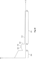
- Figure 18 shows a diagram of a spring force FF plotted over a compression distance n.
- the compression distance n is the distance by which the spring arrangement 700 is compressed.
- the spring 705 of the spring arrangement 700 can be configured as a steel disc spring and, for example, can comprise X10 CrNi 18-8 as the material.
- the spring force FF increases greatly as the compression increases along the compression distance n until the spring force FF reaches a maximum force 740 after a short compression distance n. After exceeding the maximum force 740, the spring force FF decreases sharply until the spring 705 cannot be compressed further and is compressed.
- Figure 19 shows the section E, shown in Figures 16 and 17 , while the bridge element 35 is located between the contact position and the intermediate position.
- the first pin portion 725 is guided through the guide opening 720.
- the guide element 715 remains fixed in position in the housing 15.
- the plunger portion 125 compresses the spring arrangement 700 and the springs 705 and presses them against the first receiving base 80. Owing to the spring force FF/compression distance n progression of the spring arrangement 700 already shown in Figure 17 , in the intermediate position the braking force FB, which acts counter to the actuating force FA along the lifting axis 60, is particularly strong and increases sharply as the distance of the bridge element 35 increases from the intermediate position towards the contact position up to the maximum force 740.
- the spring arrangement 700 with regard to its maximum force 740 is configured such that the maximum force 740 is already achieved well before the contact position. As a result, it can be ensured that, even when the maximum force 740 is reached, there is sufficient distance of the bridge element 35 from the switching contacts 40, 45.
- Figure 20 shows a diagram of a third graph 515 of the actuating force FA over the travel distance D of the armature 255 for displacing the bridge element 35 from the open position OP via the intermediate position ZP into the contact position KP.
- the second graph 505 is basically identical to the first graph 500.
- the second graph 505 has the first graph section 501, the second graph section 502, the third graph section 503 and at least the fourth graph section 504.
- the actuating force FA has the progression shown in Figure 20 .
- the spring arrangement 700 is compressed by the actuating force FA beyond the maximum force 740.
- the configuration of the spring 705 as a disc spring has the advantage that, as explained in Figure 19 , the spring force FF decreases with further compression of the spring arrangement 700.
- the braking force FB in the third graph section 503 is attenuated and the switching device 25 can easily compress the spring arrangement 700 until the bridge element 35 reaches the contact position.
- the overlift spring 635 can be actuated and compressed when the armature 255 is actively actuated (cf. fourth graph section 504).
- the armature 255 In the end position of the armature 255, the armature 255 can lie against a yoke of the switching device 25, and the magnetic flux is closed via the armature 255, and therefore the contact position of the bridge element 35 can be securely maintained.
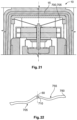
- Figure 21 shows a section E, marked in Figure 1 , of a high-current switch 10 according to a fifth embodiment.
- the high-current switch 10 is substantially identical to the high-current switch 10 shown in Figures 16 to 20 . Only the differences of the high-current switch 10, shown in Figure 21 , according to the fifth embodiment in relation to the high-current switch 10, shown in Figures 16 to 20 , according to the fourth embodiment will be discussed below.
- the first receptacle 70 is radially expanded with respect to the lifting axis 60.
- the spring arrangement 700 is wider than shown in Figures 16 to 20 .
- the number of springs 705 can be reduced compared to Figures 16 to 20 .
- the spring arrangement 700 exclusively has a spring 705.
- the spring 705 can be configured in the manner of a disc spring.
- the spring 705 is fixedly connected to the housing 15 at a radially outer end 745, for example.
- Figure 22 shows a perspective illustration of the spring 705 of the spring arrangement 700 of the high-current switch 10 shown in Figure 21 .
- the spring 705 is configured in the manner of a disc spring.
- the spring 705 can be reduced in relation to a rotationally symmetrical disc spring to the effect that the spring 705 is substantially configured in a strip-like manner in a direction perpendicular to the lifting axis 60.
- Radially on the outside the spring 705 can have a plate-like first partial section 750 for engagement in the housing 15.
- Radially on the inside of the first partial portion 750, the spring 705 has a substantially S-shaped curved progression towards the spring opening 710.
- the spring opening 710 is arranged centrally and, at the spring opening 710, the spring 705 is formed offset axially from the first partial portion 750.
Landscapes
- Physics & Mathematics (AREA)
- Electromagnetism (AREA)
- Push-Button Switches (AREA)
Priority Applications (2)
| Application Number | Priority Date | Filing Date | Title |
|---|---|---|---|
| EP23398025.9A EP4560680A1 (fr) | 2023-11-22 | 2023-11-22 | Commutateur à courant élevé et procédé de fonctionnement du commutateur à courant élevé |
| CN202411665695.5A CN120033036A (zh) | 2023-11-22 | 2024-11-20 | 高电流开关和用于操作高电流开关的方法 |
Applications Claiming Priority (1)
| Application Number | Priority Date | Filing Date | Title |
|---|---|---|---|
| EP23398025.9A EP4560680A1 (fr) | 2023-11-22 | 2023-11-22 | Commutateur à courant élevé et procédé de fonctionnement du commutateur à courant élevé |
Publications (1)
| Publication Number | Publication Date |
|---|---|
| EP4560680A1 true EP4560680A1 (fr) | 2025-05-28 |
Family
ID=89223566
Family Applications (1)
| Application Number | Title | Priority Date | Filing Date |
|---|---|---|---|
| EP23398025.9A Pending EP4560680A1 (fr) | 2023-11-22 | 2023-11-22 | Commutateur à courant élevé et procédé de fonctionnement du commutateur à courant élevé |
Country Status (2)
| Country | Link |
|---|---|
| EP (1) | EP4560680A1 (fr) |
| CN (1) | CN120033036A (fr) |
Citations (3)
| Publication number | Priority date | Publication date | Assignee | Title |
|---|---|---|---|---|
| GB2347270A (en) | 1999-02-23 | 2000-08-30 | Prestolite Electric Inc | Magnetic latching contactor |
| KR20130134169A (ko) * | 2012-05-30 | 2013-12-10 | 엘에스산전 주식회사 | 전자 개폐기 |
| US20170053763A1 (en) * | 2014-05-05 | 2017-02-23 | Valeo Equipements Electriques Moteur | Contact device of a starter contactor |
-
2023
- 2023-11-22 EP EP23398025.9A patent/EP4560680A1/fr active Pending
-
2024
- 2024-11-20 CN CN202411665695.5A patent/CN120033036A/zh active Pending
Patent Citations (3)
| Publication number | Priority date | Publication date | Assignee | Title |
|---|---|---|---|---|
| GB2347270A (en) | 1999-02-23 | 2000-08-30 | Prestolite Electric Inc | Magnetic latching contactor |
| KR20130134169A (ko) * | 2012-05-30 | 2013-12-10 | 엘에스산전 주식회사 | 전자 개폐기 |
| US20170053763A1 (en) * | 2014-05-05 | 2017-02-23 | Valeo Equipements Electriques Moteur | Contact device of a starter contactor |
Also Published As
| Publication number | Publication date |
|---|---|
| CN120033036A (zh) | 2025-05-23 |
Similar Documents
| Publication | Publication Date | Title |
|---|---|---|
| EP3748662B1 (fr) | Actionneur cinétique pour interrupteur sous vide | |
| EP0867903A2 (fr) | Dispositif d'actionnement pour disjoncteur | |
| EP2583296B1 (fr) | Relais électromagnétique | |
| EP3832684B1 (fr) | Système d'interruption | |
| US20100008009A1 (en) | Bistable electromagnetic actuator, control circuit of an electromagnetic actuator with double coil and electromagnetic actuator with double coil comprising one such control circuit | |
| US6130594A (en) | Magnetically driven electric switch | |
| US8289111B2 (en) | Electromagnetic contactor | |
| US11830694B2 (en) | Direct current relay | |
| CN115803839B (zh) | 触头装置、电磁开关、车载充电机及新能源汽车 | |
| JP2009521074A (ja) | スイッチ装置の作動方法および作動装置 | |
| CN114981672A (zh) | 接触器管理方法和提供所述方法的电池系统 | |
| CN218730704U (zh) | 继电器 | |
| US6424244B1 (en) | Magnetic switch | |
| US10431407B2 (en) | Medium voltage contactor | |
| EP4560680A1 (fr) | Commutateur à courant élevé et procédé de fonctionnement du commutateur à courant élevé | |
| KR20240151650A (ko) | 릴레이 | |
| US12009171B2 (en) | Switching device | |
| CN118369742A (zh) | 具有止动件的开关装置以及用于操作开关装置的方法 | |
| US20250285822A1 (en) | Electromagnet contact device | |
| JP2002217026A (ja) | 電磁石およびそれを用いた開閉装置の操作機構 | |
| EP4641603A1 (fr) | Structure de support mobile pour dispositif électrique | |
| US20040027775A1 (en) | Electromagnet arragement for a switch | |
| CN101622683B (zh) | 双稳态电磁促动器,双线圈电磁促动器的控制电路和包括该控制电路的双线圈电磁促动器 | |
| CN219497656U (zh) | 继电器 | |
| US8456261B2 (en) | Electromagnetic switch |
Legal Events
| Date | Code | Title | Description |
|---|---|---|---|
| PUAI | Public reference made under article 153(3) epc to a published international application that has entered the european phase |
Free format text: ORIGINAL CODE: 0009012 |
|
| STAA | Information on the status of an ep patent application or granted ep patent |
Free format text: STATUS: THE APPLICATION HAS BEEN PUBLISHED |
|
| AK | Designated contracting states |
Kind code of ref document: A1 Designated state(s): AL AT BE BG CH CY CZ DE DK EE ES FI FR GB GR HR HU IE IS IT LI LT LU LV MC ME MK MT NL NO PL PT RO RS SE SI SK SM TR |
|
| STAA | Information on the status of an ep patent application or granted ep patent |
Free format text: STATUS: REQUEST FOR EXAMINATION WAS MADE |
|
| 17P | Request for examination filed |
Effective date: 20251113 |
|
| STAA | Information on the status of an ep patent application or granted ep patent |
Free format text: STATUS: EXAMINATION IS IN PROGRESS |
|
| 17Q | First examination report despatched |
Effective date: 20260102 |