EP4560945A1 - Génération de données de substitution destinées à être utilisées dans une vérification négative dans un véhicule automobile - Google Patents
Génération de données de substitution destinées à être utilisées dans une vérification négative dans un véhicule automobile Download PDFInfo
- Publication number
- EP4560945A1 EP4560945A1 EP23211210.2A EP23211210A EP4560945A1 EP 4560945 A1 EP4560945 A1 EP 4560945A1 EP 23211210 A EP23211210 A EP 23211210A EP 4560945 A1 EP4560945 A1 EP 4560945A1
- Authority
- EP
- European Patent Office
- Prior art keywords
- data
- application
- cell
- system arrangement
- transmitted
- Prior art date
- Legal status (The legal status is an assumption and is not a legal conclusion. Google has not performed a legal analysis and makes no representation as to the accuracy of the status listed.)
- Pending
Links
Images


Classifications
-
- H—ELECTRICITY
- H04—ELECTRIC COMMUNICATION TECHNIQUE
- H04L—TRANSMISSION OF DIGITAL INFORMATION, e.g. TELEGRAPHIC COMMUNICATION
- H04L1/00—Arrangements for detecting or preventing errors in the information received
- H04L1/004—Arrangements for detecting or preventing errors in the information received by using forward error control
- H04L1/0041—Arrangements at the transmitter end
-
- H—ELECTRICITY
- H04—ELECTRIC COMMUNICATION TECHNIQUE
- H04L—TRANSMISSION OF DIGITAL INFORMATION, e.g. TELEGRAPHIC COMMUNICATION
- H04L1/00—Arrangements for detecting or preventing errors in the information received
- H04L1/004—Arrangements for detecting or preventing errors in the information received by using forward error control
- H04L1/0056—Systems characterized by the type of code used
- H04L1/007—Unequal error protection
-
- H—ELECTRICITY
- H04—ELECTRIC COMMUNICATION TECHNIQUE
- H04L—TRANSMISSION OF DIGITAL INFORMATION, e.g. TELEGRAPHIC COMMUNICATION
- H04L1/00—Arrangements for detecting or preventing errors in the information received
- H04L1/22—Arrangements for detecting or preventing errors in the information received using redundant apparatus to increase reliability
-
- H—ELECTRICITY
- H04—ELECTRIC COMMUNICATION TECHNIQUE
- H04L—TRANSMISSION OF DIGITAL INFORMATION, e.g. TELEGRAPHIC COMMUNICATION
- H04L1/00—Arrangements for detecting or preventing errors in the information received
- H04L2001/0092—Error control systems characterised by the topology of the transmission link
- H04L2001/0096—Channel splitting in point-to-point links
-
- H—ELECTRICITY
- H04—ELECTRIC COMMUNICATION TECHNIQUE
- H04L—TRANSMISSION OF DIGITAL INFORMATION, e.g. TELEGRAPHIC COMMUNICATION
- H04L1/00—Arrangements for detecting or preventing errors in the information received
- H04L2001/0098—Unequal error protection
Definitions
- the present invention is directed to a system arrangement that generates substitute data that can be used if transmitted data is negatively verified, i.e., if it is identified as faulty.
- data is replicated and transmitted redundantly at a particularly suitable location and encoded accordingly.
- various security mechanisms are integrated and synergistically linked in such a way that particularly secure data transmission in the automobile is guaranteed.
- the present invention specifically addresses the security requirements and hardware conditions in this area, which is not the case, for example, with packet-switched communication.
- the encoding makes it possible for the receiver to detect that there may be an error regarding data integrity or that data was transmitted incorrectly or not at all. If this is detected, the receiver can access the redundantly transmitted data and the data transmission is not impaired overall.
- the present invention is further directed to a correspondingly configured method that makes it possible to provide or operate the system arrangement. Furthermore, a computer program product is proposed, with control commands that execute the method or provide or operate the system arrangement.
- no packet-switched data transmission takes place in automobiles. Instead, components are permanently connected or hard-coded, meaning no dynamic switching of packets takes place, or sequential or serial data communication can be carried out.
- Particularly strict requirements for data integrity apply in automobiles, and it must be ensured at all times that transmitted data is received completely and correctly by the receiver.
- Security functions are typically implemented in automobiles that must be particularly fail-safe and reliable.
- Another requirement in automobiles is that the technical effort must be kept to a minimum and that weight must be saved. Especially in electromobility, increased energy consumption affects the range, which must be avoided at all costs.
- conventional packet-switched transmission technologies cannot be used in automobiles, as they often do not meet latency requirements or require too much effort for dynamic and packet-switched transmission. The effort consists Among other things, it involves providing components that select a dynamic data path, which is not necessary in an automobile.
- State-of-the-art technology defines a layered model as a hierarchical organizational structure. It is used to divide complex systems into manageable layers or levels, each with specific tasks and responsibilities. These layers work together to enable the overall functionality of the system.
- a state-of-the-art example of a layered model is the OSI (Open Systems Interconnection) model, used in packet-switched networking technology. It consists of seven layers, with each layer performing specific tasks related to communication between computers and devices. The layers range from the physical connection layer to the application layer, with each layer building on the services of the layer below it.
- OSI Open Systems Interconnection
- Data integrity generally refers to the accuracy, reliability, and consistency of data in an information system or database. It ensures that data remains accurate during storage, transmission, and processing and is not accidentally or maliciously altered. Ensuring data integrity is critical to ensuring that information is trustworthy and useful, especially in safety-critical applications such as automotive.
- FEC forward error correction
- FEC forward error correction
- GbE 10 Gigabit Ethernet
- Error correction mechanisms play a crucial role in ensuring reliable data transmission in networks. They help detect, isolate, and correct transmission errors to ensure data integrity is maintained. Especially in mission-critical environments where large amounts of data are transmitted, error correction mechanisms are essential to maintaining connection quality.
- the prior art recognizes the problem of faulty data transmission over a serial communication link and provides for the line-coded data to be provided with forward error correction.
- the prior art therefore addresses the problem of error correction by providing line-coded data with a non-line-coded addition, namely forward error correction, which in turn is not line-coded.
- forward error correction which in turn is not line-coded.
- the prior art has the problem that even if line coding is provided, individual metadata is transmitted unencoded and thus the advantages of line coding cannot be utilized for all transmitted data. This, in turn, represents a source of errors.
- the prior art partially overcomes this problem by separately line-coding the forward error correction data and then transmitting it. This creates additional overhead, and in order to protect the line-coded forward error correction data, a new forward error correction would have to be calculated. This, in turn, creates additional overhead and, in turn, creates non-line-coded forward error correction.
- the current state of the art is a problem in that it does not adequately analyze where in a system configuration or at which position in a process data can be replicated and transferred most effectively.
- the current state of the art does not provide reliable methods to ensure data integrity, even with redundant data transmission.
- state-of-the-art methods that transmit data in a packet-based manner are not applicable, as these are based on completely different network architectures that must ensure dynamic packet switching.
- state-of-the-art methods are created that require different security mechanisms, such as sequential or serial data transmission.
- the system arrangement should be particularly efficient yet error-robust.
- a system arrangement for generating replacement data in the event of negative verification of data to be transmitted during serial data transmission in an automobile comprising a physical application device configured to pack application data into cells of a predefined cell format, wherein the application data is received by means of a first number of input interfaces of the application device and is redundantly output to a cell multiplexing device by means of a multiple of the first number of redundant output interfaces of the application device, and wherein further application data is received by means of a second number of input interfaces of the application device and the second number of non-redundant output interfaces of the application device are output to a cell multiplexing device; and the cell multiplexing device comprising, for each output interface of the application device, a receiving interface configured to receive the application data packed in cells, wherein the cell multiplexing device is configured to forward the application data packed in cells Application data to a data transmission device which provides the application data with forward error correction.
- substitute data is generated at the sender and is used to use transmitted data in the event of a faulty transmission or coding errors.
- substitute data is the data that is used when transmitted data cannot be correctly received by the receiver.
- the receiver can verify the received data, i.e. check its correctness, and if the verification or check is negative, the substitute data can be used.
- the substitute data not only serves to check the correctness of the actual data, but also to check it, either additionally or alternatively, using forward error correction. If the actual data was transmitted correctly, the substitute data can be discarded. If a positive verification or check is carried out using forward error correction, the substitute data is deleted or no longer taken into account.
- serial data transmission Due to serial data transmission, according to one aspect of the present invention, it is not possible for individual data packets to overtake others. This can occur, for example, with packet-oriented transmission, and data is resent, for example, when a predetermined time period expires. Thus, according to the invention, it is not necessary to add further information about the sequence of the data packets. Serial data transmission takes place via a wired medium, for example, electrically or via fiber optics.
- the proposed invention is particularly preferably used in automobiles, since the fastest possible yet error-free data transmission is necessary here.
- the invention makes it possible to provide the proposed system arrangement as a single unit, meaning that all components are hard-wired to one another and cannot be separated without causing damage. This represents an advantage over the prior art, and thus, known methods of packet-switched transmission or internet technology cannot be used.
- the system arrangement comprises a physical application device which receives data from signal sources at the application level.
- a signal source can be, for example, an imaging device which, according to one aspect of the present invention, is connected to the
- the application device can therefore have multiple inputs or interfaces. These provide potentially safety-critical data that must be securely transmitted to a receiver.
- the application data is packaged in cells according to a predefined cell format.
- the data can be recoded, or the data can remain unchanged and only further information is appended.
- the data format or cell format can provide for header data to be added to the data, which, for example, describes a virtual path.
- a first port serves as an input interface
- a second port also serves as an input interface. It is possible for the first input interfaces to provide particularly safety-critical information, which is then forwarded to a plurality of output interfaces. Within the application device, the data received at the input interface is thus replicated and output at the output interfaces at a multiple of the number of input interfaces.
- the multiple in the ratio between the number of input interfaces and the number of output interfaces refers to a factor with respect to the number of output interfaces available in relation to the number of input interfaces. For example, if one input interface is provided, a multiple of this can mean two or, in another example, three output interfaces. If two input interfaces are provided, this can be three or six output interfaces in one example. This ensures that the number of data is replicated in the same ratio as the output interfaces.
- the multiple is to be interpreted such that at least two counts as a multiple. can. In this case, whole numbers do not necessarily have to be present as multiples. For example, a number of two input interfaces can lead to three output interfaces. The typical case here is that there is one input interface and two output interfaces.
- the minimum factor of two refers to the number of one input interface. If, on the other hand, there are two input interfaces, a factor of 1.5 can also apply. The only important thing here is that the number of input interfaces does not correspond to the number of output interfaces and that logically only whole numbers of input interfaces and output interfaces are present.
- the application device receives data packets or application data, and this data is implicitly replicated through the number of output interfaces. This ensures the efficient generation of redundant replacement data without requiring significant computational effort.
- the hardware interconnection of the application device alone ensures that the data is forwarded redundantly. This circuit is therefore particularly robust and less prone to errors, as no separate logic needs to be implemented.
- the data is redundantly output to a cell demultiplexing device, which then receives the packaged or encoded data.
- This device has the same number of receive interfaces as the application device has output interfaces. Communication between these two devices can take place via a communication medium such as a data line or at least a contact.
- This data channel can also be configured in such a way that virtual communication paths can be established on it.
- further application data is received via a second number of input interfaces of the application device.
- This data may be data that is not safety-critical and therefore does not need to be transmitted redundantly.
- This data can also be encoded according to the cell format, and forward error correction can also be added to this data.
- This data is simply passed through the application device and is not forwarded redundantly.
- This data is also output to the cell multiplexing device, but without replication.
- the application data can be modified or processed in the application device. Therefore, it is still referred to as application data here and is encoded in cells according to the specified cell format. Furthermore, it is also possible for additional data to be added to the application data. This not only corresponds to framework data, such as header data, but also to additional user data. Thus, this data is still present as application data, but has been edited and/or expanded or reduced.
- the data replication takes place between the application device and the cell multiplex device.
- the invention recognized that data replication must occur particularly early in the processing chain, since at this point the data is most likely still uncorrupted. This creates the advantage over the prior art that unnecessary intermediate processing steps are not performed, and the data is only saved or replicated subsequently.
- the proposed invention is based on a three-layer model, unlike conventional layer models, which are configured in seven stages. Thus, conventional layer models are not applicable, particularly since these layer models are used in packet-switched data transmission.
- the output interfaces and/or the input interfaces are each provided as physical interfaces.
- This has the advantage that the input interfaces can be implemented as conventional ports, and the physical configuration of input interfaces and output interfaces makes it possible for the application data to be replicated without computer-implemented or dynamic logic.
- the application device can interconnected in such a way that the interconnection alone replicates the data. This creates an error-robust approach that prevents data falsification.
- the application data is sent from the application device to the cell multiplexing device and/or from the cell multiplexing device to a data transmission device via virtual communication paths.
- This has the advantage that the physical communication channels can be optimally utilized, and various virtual channels can be set up via a single physical channel and also controlled separately. This makes it possible to optimize the virtual paths, for example, with regard to bandwidth utilization.
- the proposed system arrangement is particularly hardware-efficient, since a separate physical channel does not have to be created for each channel.
- the cell format provides frame data and/or at least one source identifier of a virtual path for data transmission.
- the cell format can be used to specify the virtual channel via which data is to be sent, which can be done, for example, using a channel identifier.
- a source identifier which indicates the interface from which the data originates, making it possible to trace back to what the data originally was.
- the source identifier it is possible for the source identifier to define an interface and thus indicate which path is to be selected starting from the source.
- the paths can also be virtual channels or paths or even a physical path. For example, the virtual paths can be numbered consecutively, thus assigning each path an identifier or a numerical value.
- forward error corrections can also be stored in the frame data.
- the cell format provides a numerical value that identifies a virtual path for a data transmission. This has the advantage that the virtual path can be identified using a simple method, and the application device can already determine which virtual path to select.
- a maximum of 128 virtual paths for data transmission can be established between the application device and the cell multiplexing device. This has the advantage that virtual paths can be identified based on a single byte, and it has also been empirically determined that 128 virtual paths are sufficient, especially in automobiles. This allows for efficient identification of the virtual paths.
- the data transmission device is coupled to a data reception device, which is configured to receive the application data and is further configured to check each forward error correction, and wherein, if a forward error correction check is negative, incorrect application data is replaced with redundantly transmitted application data.
- a forward error correction check is negative, incorrect application data is replaced with redundantly transmitted application data.
- the data receiving device has a cell demultiplexing device which forwards application data from the cells to an application device of the data receiving device via virtual paths.
- an application device is also provided on the receiver side which corresponds to the application device on the transmitter side, and thus the two application devices can communicate with each other.
- the transmitter device of the receiver device can be designed analogously, and thus the received data passes through the same devices inversely as on the transmitter side.
- each cell is encoded with forward error correction.
- forward error correction has the advantage that all data is provided with forward error correction, making it possible not only to detect corresponding errors but also to correct them. If this is not possible at the receiver end, the invention provides substitute data, which can then also be checked for correctness and can then replace the original data. This ensures that error-free data is always transmitted, and this can also be verified.
- the redundant application data is transmitted between the data transmission device and a data reception device via separate communication media.
- This has the advantage that errors in the communication media, such as cables, can also be detected and corrected. If one communication medium is defective, another communication medium is always available, and the replacement data can be sent via this. This also ensures error robustness in the transmission path.
- the application device, the cell multiplexing device, and/or the data transmission device are physically configured. This has the advantage of creating a particularly efficient hardware structure that is both error-robust and high-performance. This is particularly advantageous in automobiles.
- the multiple of the first number of redundant output interfaces is exactly two. This has the advantage that the data is always transmitted in duplicate, and even with a single instance of application data, two instances of application data are present, with one instance corresponding to the actual data and the second instance representing the replacement data.
- data transmission is secured through a combination of several mechanisms that work synergistically together.
- the data to be transmitted is provided with forward error correction, which allows the receiver to determine whether the data was received correctly, or the forward error correction allows the receiver to correct the data. If data verification is negative, replacement data is used, which is also provided with forward error correction. This also allows the integrity of this data to be verified, and if the original data cannot be used, this data is used. Substitute data is used.
- the first data is sent via a first transmission medium and the second data via a second, different communication medium. This ensures that the data is always available at the same time, which distinguishes the present invention from a packet-switched approach, and also ensures that a correct and functional transmission channel is selected.
- the invention ensures that if a transmission medium is defective, further data is provided via a different, separate transmission medium. This avoids errors that not only relate to the processing of the data, but also ensures, in particular, that at least one functioning transmission medium is available.
- the method only terminates if both transmission media are faulty. However, this is an atypical case and failures or impairments of the transmission medium typically only occur temporarily. This ensures that in the event of an error, which is actually detected due to forward error correction, a redundant transmission channel is available to transmit replacement data.
- multiple protection is proposed, whereby the data is redundantly encoded and the individual security mechanisms interact synergistically such that the forward error correction can also be used to select a redundant transmission channel or a redundant transmission medium. If it is detected at the receiver end that the first data is faulty, the second data transmission medium ensures that replacement data is available, which can then also be verified using forward error correction.
- the combination of these features creates the advantage over the prior art of creating a robust method or a robust system arrangement that can be provided with little technical effort.
- the present invention offers the possibility of implementing the security mechanisms purely on a hardware basis.
- the replication of the data can be carried out in such a way that there is a circuit on the transmitter end that automatically duplicates or replicates the data.
- a transmitting device which receives first data units and second data units and forwards them.
- the first transmitted data is replicated in such a way that a first instance of these data units is created and a second, identical instance of these first data units.
- the second data units are data units that are not to be transmitted redundantly.
- the data units themselves can be forwarded or encoded and, in particular, can be divided into any desired segments. These can be individual cells.
- a forward error correction is calculated for the data units, which enables the data receiver to use this forward error correction to check the accuracy of the received data and correct it if necessary.
- the forward error correction can therefore refer to the data units themselves or to individual segments. If the data units are segmented, each segment can receive a forward error correction.
- the data units can also contain framework data, such as header data, which stores the calculated forward error correction. This allows an appropriate format to be specified.
- the separate data transmission media can be a contact or a cable.
- the transmission medium can be electrical, optical, or a waveguide.
- Separate data transmission media are generally media that do not influence each other. It is therefore advantageous to electromagnetically shield the corresponding transmission media and/or to ensure that if a first medium fails, the second medium is still functional.
- the separate transmission media should not be a single contact or a single cable. This is not contradicted by the fact that both transmission media are arranged, for example, on a common printed circuit board.
- the separate transmission media as such are not virtual paths on the same Transmission medium. However, it is generally possible to operate virtual paths on each of the transmission media.
- the first instance of the first data units is sent over one communication medium and the second instance, i.e. the same, redundant data, over a second communication medium.
- the receiver can use the attached forward error correction code to determine whether the data can be transmitted correctly. If this is not the case, this may be due to faulty data processing or the transmission channels are impaired.
- the receiving device attempts to repair the received data units using the transmitted forward error correction code, which is often not possible. This is due to the natural limitations of forward error correction.
- forward error correction can generally repair minor errors, such as individual bit errors, this is not possible to an unlimited extent. If this is not possible, it is particularly advantageous that the redundant data, i.e. the second instance, can be transmitted via the second data transmission channel. This occurs in any case, as serial or sequential communication is particularly preferred, rather than packet-based communication. It is advantageous here that the first and second instances of the data units are transmitted as simultaneously as possible, ensuring that if the first instance of the data units is discarded, the second instance of the data units is already available.
- the second instance of the data units can be corrected using the forward error correction code.
- the two communication channels work synergistically together. If the correction of the first instance fails, it is still possible to check the second instance, which was transmitted via the second channel, and, if necessary, to repair it. If the transmission of the first instance fails, the second instance can be used as replacement data. The first instance is thus discarded and processing of the second instance continues without delay.
- the second coded data units are optionally transmitted to the receiving device via one of the two data transmission media.
- the second data units are transmitted, for example, via a first communication path, and as soon as further second data units are available, they are sent via the second communication path.
- One metric for selecting the data transmission medium can be, for example, checking latency times or bandwidth availability, and then the second data units are sent via the data transmission medium that currently has advantageous parameters. For example, if it is detected that the first data units are always transmitted incorrectly over a certain transmission medium, the other data transmission medium can be selected for the second data units. The selection is not static; rather, the selection for the second data units can also change dynamically at runtime.
- the system arrangement is configured for load distribution with respect to bandwidths and/or latency specifications of the two data transmission media.
- This has the advantage that the most advantageous data transmission medium can be selected for transmitting the respective data. Since the parameters can also change during runtime, selective selection also means that the data units can also be sent via the respective other data transmission medium during runtime. This applies in particular to the second data units, which can be sent via the first or second channel.
- the transmission of the coded data units over the data transmission media is sequential.
- sequential can also mean serial. This means that the data is connected in series and not packetized in such a way that one packet could overtake another.
- the data segments or data units can also be numbered consecutively and always arrive in the intended order.
- the receiving unit is configured to check and/or correct the correctness of the first instance and/or the second instance of the data units using forward error correction.
- This has the advantage that errors themselves can be detected and, moreover, an error can be corrected using forward error correction.
- Checking the forward error correction of the second instance of the data units is typically only necessary if the verification of the first data units has failed. It can then be checked whether the second instance was transmitted correctly, whether it can be corrected if necessary, and whether it can still be used to replace the first data units in the first instance.
- the receiving unit is configured to take the second instance of the data units into account if the first instance of the data units is not transmitted correctly.
- This has the advantage that valid data units are always present, and the first data units can then be discarded. Due to a possible serial or sequential transmission, it is possible for the second instance of the data units to be present in the receiver at the same time as the first instance of data units. In this way, it is possible to replace data from the first instance with data from the second instance in real time, without any delay.
- the receiving unit is configured to consider the second instance of the data units if the first instance of the data units is not transmitted.
- This has the advantage that data units that were transmitted via a different data line can be considered, thus avoiding a potential error or impairment in the first data transmission medium. Even if the first data transmission medium is damaged or not functioning according to specifications, the second transmission medium is very likely to be functional.
- first instance can each be transmitted via one of the data transmission media.
- the channel or transmission medium can be changed for the next instance of the data units.
- first instances and second instances are sent alternately via the transmission media and it can be checked which channel or data transmission medium is functioning according to the specifications. If, for example, there are five instances of the first data units, these can be sent alternately at the top and bottom, as described pictorially with reference to the figures. The same applies to the other instances of redundant data, which can also be sent alternately via the first or second channel.
- the data units are divided into cells, and a forward error correction is appended to each cell.
- a forward error correction is appended to each cell.
- the coding comprises line coding.
- This has the advantage of creating very robust signal sequences, which additionally ensure stable data transmission.
- yet another security mechanism is used, which can be advantageously integrated into the existing feature combination.
- the data units it is possible for the data units to be broken down into smaller words and, particularly advantageously, for lines to be encoded.
- Line coding is also described as line coding and should be used synonymously here.
- data transmission can be carried out via virtual paths.
- This has the advantage that a plurality of virtual paths can be operated on the physical transmission media, which virtual paths can be operated independently of one another but within the boundaries of the physical data path.
- it is possible, for example, to transmit the first data units with the second data units on the same physical level, i.e., the same physical transmission medium, wherein a first virtual path is provided for the first data units on one physical communication path and a different virtual path is provided for the second data units on the same physical transmission medium.
- the data transmission media are each provided via cables.
- This has the advantage of creating transmission channels that can be separated particularly easily, meaning that the first data transmission medium does not influence the second data transmission medium.
- it may be necessary, for example, to provide electromagnetic shielding. This ensures that the first data units and the second data units are truly transmitted separately from one another, i.e., without interaction.
- a specification of transmission parameters, including their tolerance ranges, for all data units in the two data transmission media is implemented cumulatively.
- This has the advantage that the system arrangement as a whole must be subject to a certain required performance according to a specification, and thus, it must be ensured for the transmission media which characteristics or parameters they exhibit. For example, certain latency times or a certain bandwidth may be required, which must be provided by the system arrangement as a whole, i.e., cumulatively.
- the data transmission media each support 15 gigabits per second. This has the advantage of providing sufficient bandwidth, allowing a total of 30 gigabits per second of data to be transmitted. Empirically, this has been determined to be particularly advantageous in automobiles. While faster data lines could, of course, also be provided, this would require greater technical complexity.
- a method for generating replacement data in the event of negative verification of transmitted data during serial data transmission in an automobile comprising providing a physical application device configured to pack application data into cells of a predefined cell format, wherein the application data is received by means of a first number of input interfaces of the application device and is redundantly output to a cell multiplexing device by means of a multiple of the first number of redundant output interfaces of the application device, and wherein further application data is received by means of a second number of input interfaces of the application device and the second number of non-redundant output interfaces of the application device are output to a cell multiplexing device; and providing the cell multiplexing device having, for each output interface of the application device, a receiving interface configured to receive the application data packed in cells, wherein the cell multiplexing device is configured to forward the application data packed in cells to a data transmission device, which provides the application data with forward error corrections.
- the problem is also solved by a computer program product with control commands which implement the proposed method or operate the proposed device.
- the method can be used to operate the proposed devices and units.
- the proposed devices and units are suitable for carrying out the method according to the invention.
- each device implements structural features that are suitable for carrying out the corresponding method.
- the structural features can also be configured as method steps.
- the proposed method also provides steps for implementing the function of the structural features.
- physical components can also be provided virtually or in virtualized form.
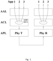
- Figure 1 shows a schematic block diagram of an architecture as can be used according to one aspect of the present invention.
- three layers are shown twice, which are analogous but inversely designed and the communication flow runs on the left side from the transmitter downwards to the receiver on the right side upwards.
- the applications APP 1, 2 and 3 are shown, which communicate with the applications on the receiver side.
- the application device is shown, below that the cell multiplex device is shown and below that the data transmission device is shown on the physical level.
- the physical transmitter On the left on the transmitter side, this is referred to as the physical transmitter and on the right side the data reception device is referred to as the physical receiver.
- the data should be multiplied or duplicated particularly advantageously between the first two upper layers. This ensures that the application data is redundantly encoded at a particularly early point in time on the upper layer, i.e., the layer between the application device and the cell multiplexing device.
- the data is also checked and corrected for errors between the cell demultiplexing device and the application device at the top right.
- the layers can also be referred to from top to bottom as Application Adaptation Layer AAL (application device), Cell Layer ACL (cell multiplexing device or cell demultiplexing device) and Physical Layer APL (data transmission device).
- Application Adaptation Layer AAL application device
- Cell Layer ACL cell multiplexing device or cell demultiplexing device
- Physical Layer APL data transmission device
- the Virtual Path Layers are the Physical Layer, which consists of the Transmission Sublayer and the Physical Medium Sublayer, the Cell Layer and the Application Adaptation Layer, which contains the Segmentation & Reassembly Sublayer and the functions for adapting the data formats to the corresponding application.
- the main task of the physical layer is to establish the physical connection to other physical layers.
- This connection is generally bidirectional. understand. Theoretically, this relationship can be realized using a variety of media. In practice, two serial differential GBps connections are used. Line coding, the insertion of idle cells to decouple the cell rate from the link rate, and the integration of the cell stream into the serial frame take place in this layer.
- the segmented data (cell payload) from the upper segmentation and reassembly sublayer is assembled into complete cells using a header, VP identifier, and CRC, or cells are CRC-checked and the payload is forwarded to the segmentation and reassembly sublayer.
- the various cell streams of the application adaptation functions are multiplexed and the cell payloads are distributed among the application adaptation functions according to the VP identifier (feed-in/feed-out).
- the cell layer also multiplexes and demultiplexes cell streams in repeaters and splitters (forwarding).
- the task of the Application Adaptation Layer is to adapt the data of the application interfaces to the format of the payload field of the cell and to transmit control information to the other side or to use control information from the other side for the adaptation (clock generation, frame construction).
- Figure 2 shows a schematic block diagram of the proposed system arrangement according to one aspect of the present invention.
- the first three units of the proposed system arrangement are shown, with the leftmost block representing the application device, the middle block, the cell multiplexing device, and the rightmost block, the data transmission device.
- the proposed invention can already be implemented using the first two left-hand blocks, with the data being transmitted redundantly between the first and second blocks.
- two applications are shown, namely Application 1 and Application 2, which each transmit data to the application device on the far left via an input interface, i.e., a port.
- the first unit, or the application device is designed such that it transmits the data of the first application redundantly and does not transmit the application data of the second application redundantly.
- the upper arrow of the data transmission between the application device and the cell multiplexing device can also be entered multiple times. In this case, only two paths are shown, namely the upper path for the redundant data and the lower path for the non-redundant data. As indicated on the cell multiplexing device, it can have multiple input interfaces or data reception interfaces. Cell 1 or cells 1 are thus transmitted multiple times, while cell 2 or cells 2 are transmitted once. In addition, the cells are each provided with forward error correction in the application device.
- the data is replicated early, i.e., already after the first device on the far left.
- the data is still highly likely to be uncorrupted.
- the data lines are encoded and/or provided with forward error correction.
- the first three devices thus represent the transmitter and are, according to the architecture, Figure 1
- the loops in the middle of the Figure 2 represent a transmission medium via which the data is transmitted from the sender to the receiver on the right-hand side.
- On the right-hand side only two devices are shown schematically, but these can also be configured as three devices, analogous to the sender.
- On the far right-hand side it is indicated that the corresponding applications 1 and 2 can use the data at the end of processing. Due to redundant transmission, the data is available multiple times with forward error correction. Thus, for example, cell 1 can be checked for correctness, and if the correctness check is negative, the substitute data is used.
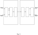
- Figure 3 shows a schematic block diagram of the proposed invention and, in particular, a system arrangement.
- the two left-hand blocks alone can implement the system arrangement. Additional blocks, i.e., blocks 3, 4, 5, and 6, are optional.
- two applications are provided on the left side, with the first application providing application data that is sent redundantly to the cell multiplex device.
- This is represented by two arrows.
- Application 2 provides non-redundant data, which is thus transmitted with one arrow.
- the arrows can be transmission media or at least a contact. Virtual data paths can be implemented on this.
- the transmitter is shown on the left side, and the receiver is shown on the right side, whereby both sides can be implemented analogously but inversely. Thus, on the receiver side, on the right
- the application device is shown on the left side, the cell demultiplexer in the middle, and the data receiving device on the left side.
- the data is transmitted from left to right, as described in the diagram, and is used by Application 1 and Application 2 on the right side.
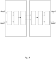
- Figure 4 also shows a schematic overview of the proposed system arrangement, with two transmission media now shown.
- the upper transmission medium can transmit the redundant application data and the lower channel, i.e. the lower communication medium, can transmit a redundant instance of this application data.
- the replacement data is transmitted via another channel.
- the non-redundant application data can be transmitted optionally via one of the channels. It is also possible for different cells of the non-redundant data to be sent via different communication media.
- a redundant data channel is created in a particularly advantageous manner which can be balanced with regard to load.
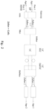
- Figure 5 shows a schematic structure of a target format according to one aspect of the present invention.
- a field is shown at the top right, which describes a virtual path VP and, for example, provides a numerical value.
- the numerical value describes the virtual channel over which the cell is to be transmitted.
- the abbreviation for a cyclic redundancy check CRC is shown at the bottom left.
- the additional data fields can be additional frame data or the payload data, which is preferably transmitted in the largest field.
- Figure 5 an example of an encoded cell that contains frame data. The cell is encoded according to the provided cell format.
- Figure 5 i.e., the coded application data, which is encoded in cell format and thus provides additional information in addition to the payload data.
- the virtual path enables, for example, redundant data transmission, so that application data packed in cells can be transmitted via a first virtual path, and the same data, i.e., the replacement data, can be transmitted via another virtual path.
- the packaged application data as it is in Figure 5 shown, according to this cell, whereby only the field of the virtual path is adjusted.
- Figure 6 shows, in a schematic flow diagram, a method for generating replacement data in the event of negative verification of transmitted data in a serial data transmission in an automobile, comprising providing 100 a physical application device configured to package 102 application data into cells of a predefined cell format, wherein the application data is received 101 by means of a first number of input interfaces of the application device and is redundantly output 103 to a cell multiplexing device by means of a multiple of the first number of redundant output interfaces of the application device, and wherein further application data is received 104 by means of a second number of input interfaces of the application device and the second number of non-redundant output interfaces of the application device are output 105 to a cell multiplexing device; and providing 106 the cell multiplexing device having, for each output interface of the application device, a receiving interface configured to receive 107 the application data packed in cells, wherein the cell multiplexing device is configured to forward 108 the application data packed in cells to a data transmission device which provides the application data with forward error corrections 109.
- a system arrangement for securing a data transmission comprising a transmitting device configured for redundant coding of first data units into a first instance of the first data units and a second identical and thus redundant instance of the first data units, and further configured for coding second data units, wherein in all codings an addition of a forward error correction is carried out; and exactly two physical, separate Data transmission media which communicatively couple the transmitting device and a receiving device, wherein the transmitting device is configured to transmit the first instance of the first data units via exclusively one data transmission medium and to transmit the second instance of the first data units via exclusively the other data transmission medium and further to transmit the second coded data units to the receiving device via an optional one of the two data transmission media.
Landscapes
- Engineering & Computer Science (AREA)
- Computer Networks & Wireless Communication (AREA)
- Signal Processing (AREA)
- Detection And Prevention Of Errors In Transmission (AREA)
Priority Applications (2)
| Application Number | Priority Date | Filing Date | Title |
|---|---|---|---|
| EP23211210.2A EP4560945A1 (fr) | 2023-11-21 | 2023-11-21 | Génération de données de substitution destinées à être utilisées dans une vérification négative dans un véhicule automobile |
| PCT/EP2024/076649 WO2025108602A1 (fr) | 2023-11-21 | 2024-09-23 | Génération de données de substitution destinées à être utilisées en cas de vérification négative dans des automobiles |
Applications Claiming Priority (1)
| Application Number | Priority Date | Filing Date | Title |
|---|---|---|---|
| EP23211210.2A EP4560945A1 (fr) | 2023-11-21 | 2023-11-21 | Génération de données de substitution destinées à être utilisées dans une vérification négative dans un véhicule automobile |
Publications (1)
| Publication Number | Publication Date |
|---|---|
| EP4560945A1 true EP4560945A1 (fr) | 2025-05-28 |
Family
ID=88921000
Family Applications (1)
| Application Number | Title | Priority Date | Filing Date |
|---|---|---|---|
| EP23211210.2A Pending EP4560945A1 (fr) | 2023-11-21 | 2023-11-21 | Génération de données de substitution destinées à être utilisées dans une vérification négative dans un véhicule automobile |
Country Status (2)
| Country | Link |
|---|---|
| EP (1) | EP4560945A1 (fr) |
| WO (1) | WO2025108602A1 (fr) |
Citations (4)
| Publication number | Priority date | Publication date | Assignee | Title |
|---|---|---|---|---|
| WO2001046765A1 (fr) * | 1999-12-22 | 2001-06-28 | Rockwell Technologies, Llc | Reseau de securite pour un controleur industriel ayant des imperatifs de largeur de bande reduits |
| US20090034633A1 (en) * | 2007-07-31 | 2009-02-05 | Cisco Technology, Inc. | Simultaneous processing of media and redundancy streams for mitigating impairments |
| US20100138573A1 (en) * | 2008-12-01 | 2010-06-03 | Fujitsu Limited | System including transmitter and receiver |
| US20120082260A1 (en) * | 2007-04-05 | 2012-04-05 | Hyoung Gon Lee | Digital broadcasting system and method of processing data |
-
2023
- 2023-11-21 EP EP23211210.2A patent/EP4560945A1/fr active Pending
-
2024
- 2024-09-23 WO PCT/EP2024/076649 patent/WO2025108602A1/fr active Pending
Patent Citations (4)
| Publication number | Priority date | Publication date | Assignee | Title |
|---|---|---|---|---|
| WO2001046765A1 (fr) * | 1999-12-22 | 2001-06-28 | Rockwell Technologies, Llc | Reseau de securite pour un controleur industriel ayant des imperatifs de largeur de bande reduits |
| US20120082260A1 (en) * | 2007-04-05 | 2012-04-05 | Hyoung Gon Lee | Digital broadcasting system and method of processing data |
| US20090034633A1 (en) * | 2007-07-31 | 2009-02-05 | Cisco Technology, Inc. | Simultaneous processing of media and redundancy streams for mitigating impairments |
| US20100138573A1 (en) * | 2008-12-01 | 2010-06-03 | Fujitsu Limited | System including transmitter and receiver |
Also Published As
| Publication number | Publication date |
|---|---|
| WO2025108602A1 (fr) | 2025-05-30 |
Similar Documents
| Publication | Publication Date | Title |
|---|---|---|
| EP2838220A1 (fr) | Procédé de transmission redondante de messages dans un réseau de communication industriel et appareil de communication | |
| EP2506502B1 (fr) | Système d'automatisation redondant | |
| EP3977682A1 (fr) | Dispositif de test de détection d'erreur pour une station d'abonné d'un système de bus série et procédé de test de mécanismes de détection d'erreur lors d'une communication dans un système de bus série | |
| DE102013217595A1 (de) | Bereitstellung unterschiedlicher Datenübertragungsraten und Redundanz durch gemeinsame und getrennte Nutzung von physikalischen Übertragungskanälen im Kraftfahrzeug | |
| EP1802019B1 (fr) | Détection d'erreurs lors de la transmission de données | |
| DE69625953T2 (de) | Methode und Vorrichtung zum Erreichen hoher Unversehrtheit und Verfügbarkeit in einem mehrkanaligen System | |
| DE112006001165B4 (de) | Kommunikationsvorrichtung und Schalteinrichtung | |
| DE102022207044A1 (de) | Netzwerkvorrichtung- sicherheitsprotokoll | |
| EP2880823A1 (fr) | Réseau de communication et procédé d'exploitation d'un réseau de communication | |
| DE10031177A1 (de) | Verfahren und Anordnung zur gesicherten paketorientierten Informationsübermittlung | |
| EP1469625B1 (fr) | Procédé et dispositf pour la transmission par paquets des données relatives à la sécurité. | |
| DE10305415B4 (de) | Verfahren und Vorrichtung zum medienredundanten Betreiben eines Endgeräts in einem Netzwerk | |
| EP4033714B1 (fr) | Procédé de transfert de données entre deux composants de véhicule à commande numérique | |
| EP4560945A1 (fr) | Génération de données de substitution destinées à être utilisées dans une vérification négative dans un véhicule automobile | |
| EP4560946A1 (fr) | Protection matérielle d'une transmission de données dans une automobile pour envoyer des données sur plusieurs canaux | |
| DE102021127310B4 (de) | System und Verfahren zur Datenübertragung | |
| EP1596517B1 (fr) | Procédé de transmission sur un seul canal de données fournies sous forme redondante | |
| WO2003028279A2 (fr) | Messages de remplacement pour detecter et eviter des erreurs lors de la transmission de donnees critiques en temps reel | |
| EP4070511A1 (fr) | Station d'abonné pour un système de bus série et procédé de communication dans un système de bus série | |
| DE102019106410A1 (de) | Vorrichtung und Verfahren zur Datenübertragung | |
| EP1686732A1 (fr) | Procédé et système de transmission d'unités de données de protocole | |
| DE102020209363A1 (de) | Verfahren und sicherheitsgerichtetes System zum Ausführen von Sicherheitsfunktionen | |
| EP3457232B1 (fr) | Procédé de fonctionnement d'un système d'automatisation à haute disponibilité | |
| DE102013204891B4 (de) | Verfahren zur Rekonstruktion von Messdaten | |
| DE102013204371A1 (de) | Verfahren und Bussystem zum protokollunabhängigen Übertragen von Standarddatenpaketen mit Sicherheitsdaten |
Legal Events
| Date | Code | Title | Description |
|---|---|---|---|
| PUAI | Public reference made under article 153(3) epc to a published international application that has entered the european phase |
Free format text: ORIGINAL CODE: 0009012 |
|
| STAA | Information on the status of an ep patent application or granted ep patent |
Free format text: STATUS: REQUEST FOR EXAMINATION WAS MADE |
|
| 17P | Request for examination filed |
Effective date: 20231121 |
|
| AK | Designated contracting states |
Kind code of ref document: A1 Designated state(s): AL AT BE BG CH CY CZ DE DK EE ES FI FR GB GR HR HU IE IS IT LI LT LU LV MC ME MK MT NL NO PL PT RO RS SE SI SK SM TR |
|
| RAP3 | Party data changed (applicant data changed or rights of an application transferred) |
Owner name: INOVA SEMICONDUCTORS GMBH |