EP4560952A2 - Verfahren und vorrichtung zur übertragung/konfiguration von uplink-steuerungsinformationen, endgerät und basisstation - Google Patents
Verfahren und vorrichtung zur übertragung/konfiguration von uplink-steuerungsinformationen, endgerät und basisstation Download PDFInfo
- Publication number
- EP4560952A2 EP4560952A2 EP25169548.2A EP25169548A EP4560952A2 EP 4560952 A2 EP4560952 A2 EP 4560952A2 EP 25169548 A EP25169548 A EP 25169548A EP 4560952 A2 EP4560952 A2 EP 4560952A2
- Authority
- EP
- European Patent Office
- Prior art keywords
- information
- group
- sending
- transmission
- configuration
- Prior art date
- Legal status (The legal status is an assumption and is not a legal conclusion. Google has not performed a legal analysis and makes no representation as to the accuracy of the status listed.)
- Pending
Links
Images



Classifications
-
- H—ELECTRICITY
- H04—ELECTRIC COMMUNICATION TECHNIQUE
- H04L—TRANSMISSION OF DIGITAL INFORMATION, e.g. TELEGRAPHIC COMMUNICATION
- H04L1/00—Arrangements for detecting or preventing errors in the information received
- H04L1/0001—Systems modifying transmission characteristics according to link quality, e.g. power backoff
- H04L1/0023—Systems modifying transmission characteristics according to link quality, e.g. power backoff characterised by the signalling
- H04L1/0028—Formatting
- H04L1/0031—Multiple signaling transmission
-
- H—ELECTRICITY
- H04—ELECTRIC COMMUNICATION TECHNIQUE
- H04B—TRANSMISSION
- H04B7/00—Radio transmission systems, i.e. using radiation field
- H04B7/02—Diversity systems; Multi-antenna system, i.e. transmission or reception using multiple antennas
- H04B7/04—Diversity systems; Multi-antenna system, i.e. transmission or reception using multiple antennas using two or more spaced independent antennas
- H04B7/0413—MIMO systems
- H04B7/0417—Feedback systems
-
- H—ELECTRICITY
- H04—ELECTRIC COMMUNICATION TECHNIQUE
- H04B—TRANSMISSION
- H04B7/00—Radio transmission systems, i.e. using radiation field
- H04B7/02—Diversity systems; Multi-antenna system, i.e. transmission or reception using multiple antennas
- H04B7/04—Diversity systems; Multi-antenna system, i.e. transmission or reception using multiple antennas using two or more spaced independent antennas
- H04B7/06—Diversity systems; Multi-antenna system, i.e. transmission or reception using multiple antennas using two or more spaced independent antennas at the transmitting station
- H04B7/0613—Diversity systems; Multi-antenna system, i.e. transmission or reception using multiple antennas using two or more spaced independent antennas at the transmitting station using simultaneous transmission
- H04B7/0615—Diversity systems; Multi-antenna system, i.e. transmission or reception using multiple antennas using two or more spaced independent antennas at the transmitting station using simultaneous transmission of weighted versions of same signal
- H04B7/0619—Diversity systems; Multi-antenna system, i.e. transmission or reception using multiple antennas using two or more spaced independent antennas at the transmitting station using simultaneous transmission of weighted versions of same signal using feedback from receiving side
- H04B7/0621—Feedback content
- H04B7/0626—Channel coefficients, e.g. channel state information [CSI]
-
- H—ELECTRICITY
- H04—ELECTRIC COMMUNICATION TECHNIQUE
- H04B—TRANSMISSION
- H04B7/00—Radio transmission systems, i.e. using radiation field
- H04B7/02—Diversity systems; Multi-antenna system, i.e. transmission or reception using multiple antennas
- H04B7/04—Diversity systems; Multi-antenna system, i.e. transmission or reception using multiple antennas using two or more spaced independent antennas
- H04B7/06—Diversity systems; Multi-antenna system, i.e. transmission or reception using multiple antennas using two or more spaced independent antennas at the transmitting station
- H04B7/0613—Diversity systems; Multi-antenna system, i.e. transmission or reception using multiple antennas using two or more spaced independent antennas at the transmitting station using simultaneous transmission
- H04B7/0615—Diversity systems; Multi-antenna system, i.e. transmission or reception using multiple antennas using two or more spaced independent antennas at the transmitting station using simultaneous transmission of weighted versions of same signal
- H04B7/0619—Diversity systems; Multi-antenna system, i.e. transmission or reception using multiple antennas using two or more spaced independent antennas at the transmitting station using simultaneous transmission of weighted versions of same signal using feedback from receiving side
- H04B7/0621—Feedback content
- H04B7/0632—Channel quality parameters, e.g. channel quality indicator [CQI]
-
- H—ELECTRICITY
- H04—ELECTRIC COMMUNICATION TECHNIQUE
- H04B—TRANSMISSION
- H04B7/00—Radio transmission systems, i.e. using radiation field
- H04B7/02—Diversity systems; Multi-antenna system, i.e. transmission or reception using multiple antennas
- H04B7/04—Diversity systems; Multi-antenna system, i.e. transmission or reception using multiple antennas using two or more spaced independent antennas
- H04B7/06—Diversity systems; Multi-antenna system, i.e. transmission or reception using multiple antennas using two or more spaced independent antennas at the transmitting station
- H04B7/0613—Diversity systems; Multi-antenna system, i.e. transmission or reception using multiple antennas using two or more spaced independent antennas at the transmitting station using simultaneous transmission
- H04B7/0615—Diversity systems; Multi-antenna system, i.e. transmission or reception using multiple antennas using two or more spaced independent antennas at the transmitting station using simultaneous transmission of weighted versions of same signal
- H04B7/0619—Diversity systems; Multi-antenna system, i.e. transmission or reception using multiple antennas using two or more spaced independent antennas at the transmitting station using simultaneous transmission of weighted versions of same signal using feedback from receiving side
- H04B7/0636—Feedback format
- H04B7/0639—Using selective indices, e.g. of a codebook, e.g. pre-distortion matrix index [PMI] or for beam selection
-
- H—ELECTRICITY
- H04—ELECTRIC COMMUNICATION TECHNIQUE
- H04L—TRANSMISSION OF DIGITAL INFORMATION, e.g. TELEGRAPHIC COMMUNICATION
- H04L1/00—Arrangements for detecting or preventing errors in the information received
- H04L1/02—Arrangements for detecting or preventing errors in the information received by diversity reception
- H04L1/06—Arrangements for detecting or preventing errors in the information received by diversity reception using space diversity
-
- H—ELECTRICITY
- H04—ELECTRIC COMMUNICATION TECHNIQUE
- H04L—TRANSMISSION OF DIGITAL INFORMATION, e.g. TELEGRAPHIC COMMUNICATION
- H04L1/00—Arrangements for detecting or preventing errors in the information received
- H04L1/12—Arrangements for detecting or preventing errors in the information received by using return channel
- H04L1/16—Arrangements for detecting or preventing errors in the information received by using return channel in which the return channel carries supervisory signals, e.g. repetition request signals
-
- H—ELECTRICITY
- H04—ELECTRIC COMMUNICATION TECHNIQUE
- H04L—TRANSMISSION OF DIGITAL INFORMATION, e.g. TELEGRAPHIC COMMUNICATION
- H04L1/00—Arrangements for detecting or preventing errors in the information received
- H04L1/12—Arrangements for detecting or preventing errors in the information received by using return channel
- H04L1/16—Arrangements for detecting or preventing errors in the information received by using return channel in which the return channel carries supervisory signals, e.g. repetition request signals
- H04L1/1607—Details of the supervisory signal
- H04L1/1671—Details of the supervisory signal the supervisory signal being transmitted together with control information
-
- H—ELECTRICITY
- H04—ELECTRIC COMMUNICATION TECHNIQUE
- H04L—TRANSMISSION OF DIGITAL INFORMATION, e.g. TELEGRAPHIC COMMUNICATION
- H04L27/00—Modulated-carrier systems
- H04L27/26—Systems using multi-frequency codes
- H04L27/2601—Multicarrier modulation systems
- H04L27/2602—Signal structure
- H04L27/2605—Symbol extensions, e.g. Zero Tail, Unique Word [UW]
- H04L27/2607—Cyclic extensions
-
- H—ELECTRICITY
- H04—ELECTRIC COMMUNICATION TECHNIQUE
- H04L—TRANSMISSION OF DIGITAL INFORMATION, e.g. TELEGRAPHIC COMMUNICATION
- H04L27/00—Modulated-carrier systems
- H04L27/26—Systems using multi-frequency codes
- H04L27/2601—Multicarrier modulation systems
- H04L27/2626—Arrangements specific to the transmitter only
- H04L27/2627—Modulators
- H04L27/2628—Inverse Fourier transform modulators, e.g. inverse fast Fourier transform [IFFT] or inverse discrete Fourier transform [IDFT] modulators
-
- H—ELECTRICITY
- H04—ELECTRIC COMMUNICATION TECHNIQUE
- H04L—TRANSMISSION OF DIGITAL INFORMATION, e.g. TELEGRAPHIC COMMUNICATION
- H04L5/00—Arrangements affording multiple use of the transmission path
- H04L5/003—Arrangements for allocating sub-channels of the transmission path
- H04L5/0053—Allocation of signalling, i.e. of overhead other than pilot signals
-
- H—ELECTRICITY
- H04—ELECTRIC COMMUNICATION TECHNIQUE
- H04L—TRANSMISSION OF DIGITAL INFORMATION, e.g. TELEGRAPHIC COMMUNICATION
- H04L5/00—Arrangements affording multiple use of the transmission path
- H04L5/0091—Signalling for the administration of the divided path, e.g. signalling of configuration information
- H04L5/0092—Indication of how the channel is divided
-
- H—ELECTRICITY
- H04—ELECTRIC COMMUNICATION TECHNIQUE
- H04W—WIRELESS COMMUNICATION NETWORKS
- H04W72/00—Local resource management
- H04W72/04—Wireless resource allocation
-
- H—ELECTRICITY
- H04—ELECTRIC COMMUNICATION TECHNIQUE
- H04W—WIRELESS COMMUNICATION NETWORKS
- H04W72/00—Local resource management
- H04W72/12—Wireless traffic scheduling
-
- H—ELECTRICITY
- H04—ELECTRIC COMMUNICATION TECHNIQUE
- H04W—WIRELESS COMMUNICATION NETWORKS
- H04W72/00—Local resource management
- H04W72/12—Wireless traffic scheduling
- H04W72/1263—Mapping of traffic onto schedule, e.g. scheduled allocation or multiplexing of flows
- H04W72/1268—Mapping of traffic onto schedule, e.g. scheduled allocation or multiplexing of flows of uplink data flows
-
- H—ELECTRICITY
- H04—ELECTRIC COMMUNICATION TECHNIQUE
- H04W—WIRELESS COMMUNICATION NETWORKS
- H04W72/00—Local resource management
- H04W72/20—Control channels or signalling for resource management
- H04W72/21—Control channels or signalling for resource management in the uplink direction of a wireless link, i.e. towards the network
-
- H—ELECTRICITY
- H04—ELECTRIC COMMUNICATION TECHNIQUE
- H04W—WIRELESS COMMUNICATION NETWORKS
- H04W72/00—Local resource management
- H04W72/20—Control channels or signalling for resource management
- H04W72/23—Control channels or signalling for resource management in the downlink direction of a wireless link, i.e. towards a terminal
-
- H—ELECTRICITY
- H04—ELECTRIC COMMUNICATION TECHNIQUE
- H04W—WIRELESS COMMUNICATION NETWORKS
- H04W72/00—Local resource management
- H04W72/50—Allocation or scheduling criteria for wireless resources
- H04W72/53—Allocation or scheduling criteria for wireless resources based on regulatory allocation policies
-
- H—ELECTRICITY
- H04—ELECTRIC COMMUNICATION TECHNIQUE
- H04W—WIRELESS COMMUNICATION NETWORKS
- H04W72/00—Local resource management
- H04W72/50—Allocation or scheduling criteria for wireless resources
- H04W72/535—Allocation or scheduling criteria for wireless resources based on resource usage policies
-
- H—ELECTRICITY
- H04—ELECTRIC COMMUNICATION TECHNIQUE
- H04W—WIRELESS COMMUNICATION NETWORKS
- H04W72/00—Local resource management
- H04W72/50—Allocation or scheduling criteria for wireless resources
- H04W72/54—Allocation or scheduling criteria for wireless resources based on quality criteria
-
- H—ELECTRICITY
- H04—ELECTRIC COMMUNICATION TECHNIQUE
- H04L—TRANSMISSION OF DIGITAL INFORMATION, e.g. TELEGRAPHIC COMMUNICATION
- H04L1/00—Arrangements for detecting or preventing errors in the information received
- H04L1/0001—Systems modifying transmission characteristics according to link quality, e.g. power backoff
- H04L1/0023—Systems modifying transmission characteristics according to link quality, e.g. power backoff characterised by the signalling
- H04L1/0026—Transmission of channel quality indication
-
- H—ELECTRICITY
- H04—ELECTRIC COMMUNICATION TECHNIQUE
- H04L—TRANSMISSION OF DIGITAL INFORMATION, e.g. TELEGRAPHIC COMMUNICATION
- H04L5/00—Arrangements affording multiple use of the transmission path
- H04L5/0001—Arrangements for dividing the transmission path
- H04L5/0003—Two-dimensional division
- H04L5/0005—Time-frequency
- H04L5/0007—Time-frequency the frequencies being orthogonal, e.g. OFDM(A) or DMT
-
- H—ELECTRICITY
- H04—ELECTRIC COMMUNICATION TECHNIQUE
- H04L—TRANSMISSION OF DIGITAL INFORMATION, e.g. TELEGRAPHIC COMMUNICATION
- H04L5/00—Arrangements affording multiple use of the transmission path
- H04L5/0001—Arrangements for dividing the transmission path
- H04L5/0014—Three-dimensional division
- H04L5/0023—Time-frequency-space
Definitions
- the present invention relates to communications and, in particular, to an uplink control information transmission/configuration indication method and device, a terminal and a base station.
- the L1/L2 uplink control information includes a scheduling request (SR), a hybrid automatic repeat request (HARQ) acknowledgement/negative acknowledgement (ACK/NACK) and channel state information (CSI).
- SR scheduling request
- HARQ hybrid automatic repeat request
- ACK/NACK channel state information
- CSI channel state information
- the SR is used for requesting uplink shared channel (UL-SCH) resources from an eNodeB;
- the HARQ-ACK/NACK is used for HARQ acknowledge downlink data sent on a data channel, a physical downlink share channel (PDSCH).
- UL-SCH uplink shared channel
- PDSCH physical downlink share channel
- the CSI includes a channel quality indication (CQI), a precoding matrix indicator/index (PMI), a rank indicator (RI), a channel state information reference signal (CSI-RS) resource indicator/index resource indicator/index (CRI) and the like, and is used for notifying an eNodeB of a downlink channel quality to help the eNodeB with downlink scheduling.
- CQI channel quality indication
- PMI precoding matrix indicator/index
- RI rank indicator
- CSI-RS channel state information reference signal
- the control information in the LTE is transmitted in two manners. If no uplink resource in a current subframe is allocated to UE for sending uplink data, the UE sends the L1/L2 uplink control information in the physical uplink control channel (PUCCH). If one or more uplink resources in the current subframe are allocated to the UE for sending the uplink data, the UE sends the L1/L2 uplink control information on part of resources allocated to the physical shared control channel (PUSCH). If the resources have been allocated to the UE for sending the uplink data, it is not necessary to send the SR. In the case of carrier aggregation (CA), the control information of multiple carriers may be aggregated together for sending.
- CA carrier aggregation
- Table 1 Format Information 1 SR 1a 1-bit ACK/NACK with/without SR 1b 2-bit ACK/NACK with/without SR 2 20-bit CSI 2 20-bit CSI + 1 or 2-bit ACK/NACK (only for extended CP) 2a 20-bit CSI + 1-bit ACK/NACK (only for normal CP) 2b 20-bit CSI + 2-bit ACK/NACK (only for normal CP) 3
- FDD up to 10-bit ACK/NACK
- For frequency division duplex TDD up to 20-bit ACK/NACK 3
- FDD up to 10-bit ACK/NACK + 1-bit SR
- TDD up to 20-bit ACK/NACK + 1-bit SR
- control information may be separately transmitted, or may be transmitted in combination with other types of control information, thereby respectively forming different formats.
- the transmission of the same format in the same antenna configuration has a relatively fixed design and cannot be flexibly changed.
- the robustness of the transmitted content is the primary consideration in the LTE. A low error rate is required in transmission of the control information, because an error in the control information may cause more serious consequences than an error in data information. Therefore, the control information is transmitted in the most robust manner.
- the uplink control channel generally distinguishes different users through code division.
- the code division may adopt different orthogonal sequences or perform cyclic shift with the same sequence to achieve orthogonality.
- the LTE/LTE-A is mainly intended for frequencies with relatively low communication frequencies.
- the path loss in the system is not large. But with the development and utilization of high frequencies, the communication frequency of the system is getting higher, and is gradually extended up to 4 GHz, 30 GHz and even 70 GHz. At this time, the path loss will significantly increase.
- beam transmission is used to acquire beamforming gain so that coverage of the control channel can be ensured, which has become a trend.
- the beam transmission requires real-time accurate CSI.
- the rotation of the terminal may affect the accuracy of the beam. In this case, the robustness of the control channel is challenged.
- the problem of control information feedback is that if the uplink control information is transmitted in the most robust manner, the uplink control information is required to be transmitted in all beam directions, each direction needs to occupy resources, and the number of beams is generally twice the number of antennas. In this case, a large amount of resources are required. Nevertheless, if the uplink control information is transmitted in the manner with the highest transmission efficiency, the robustness problem will occur. In a word, the beam always has the problem in measurement accuracy and real-time capability. Therefore, there is a lack of a transmission manner that guarantees both robustness and high transmission efficiency at the same time during the transmission of the control information.
- An uplink control information transmission method is provided according to embodiments of the present application.
- the method includes:
- the step of determining a transmission configuration set corresponding to uplink control information to be sent includes:
- the step of selecting a transmission configuration from the transmission configuration set includes one of:
- the downlink control signaling is physical layer signaling.
- the step of determining a transmission configuration set corresponding to uplink control information to be sent includes: determining the transmission configuration set according to a responded object, or selecting the transmission configuration according to times of retransmission; or
- the uplink control information includes at least one of: a response message, a scheduling request message, CSI, sending manner switching request information, receiving manner switching feedback information, or indication information of information reporting mode.
- the configuration in the transmission configuration set includes at least one of: at least one configuration of numerology, at least one configuration of sending code sequence set, at least one configuration of sending power, at least one configuration of sending times, at least one configuration of sending resource quantity, at least one configuration of sending resource granularity, at least one configuration of modulation manner, at least one configuration of coding manner, at least one configuration of sending manner, at least one configuration of receiving manner, or at least one configuration of transmission area.
- the configuration of numerology includes at least one of: a time domain symbol length, a subcarrier spacing, a number of points in fast Fourier transform (FFT) algorithm, a subcarrier density, a cyclic prefix (CP) length, a frequency domain guard band, or a guard period (GP); and/or
- FFT fast Fourier transform
- CP cyclic prefix
- GP guard period
- an uplink control information transmission method includes:
- the M transmission areas at least include an area i and an area j, for transmission in the area i and the area j, a sending power offset P exists between the area i and the area j, where the sending power offset P is configured by a base station; and/or
- the uplink control information includes at least one of: a response message, a scheduling request message, CSI, sending manner switching request information, receiving manner switching feedback information, or indication information of information reporting mode.
- an uplink control information transmission method is further provided. The method includes:
- the method further includes: dividing the information into a number X of groups according to a type of the uplink control information, where X is an integer greater than or equal to 1.
- the uplink control information includes at least one of: a response message, a scheduling request message, CSI, sending manner switching request information, receiving manner switching feedback information, or indication information of information reporting mode.
- the CSI at least includes: a channel quality indicator/index (CQI), a precoding matrix indicator (PMI), a rank indicator (RI) of a channel, a channel state information reference signal resource indicator/index (CRI), port selection information, and a beam indicator/index (BI).
- the method further includes: dividing the uplink control information into two groups.
- a first group of the two group includes at least one of: a scheduling request message, a response message, a beam indicator/index (BI), a channel state information reference signal resource indicator/index (CRI), a rank indicator (RI), sending manner switching request information, receiving manner switching feedback information, or indication information of information reporting mode, and a second group includes at least one of: a channel quality indicator/index (CQI) or a precoding matrix indicator (PMI); or
- sending power corresponding to the second group is less than or equal to sending power corresponding to the first group
- the sending sector of the second group is a subset of the sending sector of the first group.
- an uplink control information transmission configuration indication method is further provided.
- the method includes:
- the transmission configuration includes at least one of: a configuration of numerology, a configuration of sending code sequence set, a configuration of sending power, a configuration of sending times, a configuration of sending resource quantity, a configuration of sending resource granularity, a configuration of modulation manner, a configuration of coding manner, a configuration of sending manner, a configuration of receiving manner, or a configuration of transmission area.
- the configuration of numerology includes at least one of: a time domain symbol length, a subcarrier spacing, a number of points in fast Fourier transform (FFT) algorithm, a subcarrier density, a cyclic prefix (CP) length, a frequency domain guard band, or a guard period (GP); and/or
- FFT fast Fourier transform
- CP cyclic prefix
- GP guard period
- the uplink control information includes at least one of: a response message, a scheduling request message, CSI, sending manner switching request information, receiving manner switching feedback information, or indication information of information reporting mode.
- an uplink control information transmission configuration indication method is further provided. The method includes:
- the transmission configuration includes at least one of: a configuration of numerology, a configuration of sending code sequence set, a configuration of sending power, a configuration of sending times, a configuration of sending resource quantity, a configuration of sending resource granularity, a configuration of modulation manner, a configuration of coding manner, a configuration of sending manner, a configuration of receiving manner, or a configuration of transmission area.
- the configuration of numerology includes at least one of: a time domain symbol length, a subcarrier spacing, a number of points in fast Fourier transform (FFT) algorithm, a subcarrier density, a cyclic prefix (CP) length, a frequency domain guard band, or a guard period (GP); and/or
- FFT fast Fourier transform
- CP cyclic prefix
- GP guard period
- the uplink control information includes at least one of: a response message, a scheduling request message, CSI, sending manner switching request information, receiving manner switching feedback information, or indication information of information reporting mode.
- an uplink control information transmission device is further provided. The device includes:
- the first determining module includes a first determining unit.
- the first determining unit is configured to: determine the transmission configuration set according to an information type of the uplink control information to be sent; determine the transmission configuration set according to an indication of downlink control signaling; or determine the transmission configuration set according to an uplink or downlink transmission mode.
- the first determining unit is further configured to: when the transmission configuration set includes a plurality of transmission configurations, select the transmission configuration from the transmission configuration set according to the information type of the uplink control information to be sent; select the transmission configuration from the transmission configuration set according to the indication of the downlink control signaling; or select the transmission configuration from the transmission configuration set according to the uplink or downlink transmission mode.
- the first determining module includes a second determining unit.
- the second determining unit is configured to, when the uplink control information to be sent includes response information, determine the transmission configuration set according to a responded object, or select the transmission configuration according to times of retransmission; or when the uplink control information to be sent includes channel state information (CSI), determine the transmission configuration set according to a type of the CSI.
- CSI channel state information
- the first selecting module is further configured to: in determination of the transmission configuration set according to the responded object, select the transmission configuration according to the responded object, or select the transmission configuration according to times of retransmission; or in determination of the transmission configuration set according to the type of the CSI, the selecting a transmission configuration from the transmission configuration set includes: selecting the transmission configuration according to the type of the CSI.
- an uplink control information transmission device is further provided.
- the device includes:
- the M transmission areas at least include an area i and an area j, for transmission in the area i and the area j, a sending power offset P exists between the area i and the area j, where the sending power offset P is configured by a base station; and/or
- an uplink control information transmission device is further provided.
- the device includes:
- the device further includes a grouping module.
- the grouping module is configured to divide the uplink control information into two groups.
- a first group of the two group includes at least one of: a scheduling request message, a response message, a beam indicator/index (BI), a channel state information reference signal resource indicator/index (CRI), a rank indicator (RI), sending manner switching request information, receiving manner switching feedback information, or indication information of information reporting mode, and a second group includes at least one of: a channel quality indicator/index (CQI) or a precoding matrix indicator (PMI); or
- an uplink control information transmission configuration indication device is further provided.
- the device includes:
- the transmission configuration includes at least one of: a configuration of numerology, a configuration of sending code sequence set, a configuration of sending power, a configuration of sending times, a configuration of sending resource quantity, a configuration of sending resource granularity, a configuration of modulation manner, a configuration of coding manner, a configuration of sending manner, a configuration of receiving manner, or a configuration of transmission area.
- an uplink control information transmission configuration indication device is further provided.
- the device includes:
- the transmission configuration includes at least one of: a configuration of numerology, a configuration of sending code sequence set, a configuration of sending power, a configuration of sending times, a configuration of sending resource quantity, a configuration of sending resource granularity, a configuration of modulation manner, a configuration of coding manner, a configuration of sending manner, a configuration of receiving manner, or a configuration of transmission area.
- a terminal is further provided.
- the terminal includes a processor and a memory storing processor-executable instructions which, when executed by the processor, execute following operations:
- the processor is configured to further execute the following operations: determining the transmission configuration set according to an information type of the uplink control information to be sent; determining the transmission configuration set according to an indication of downlink control signaling; or determining the transmission configuration set according to an uplink or downlink transmission mode.
- a base station is further provided.
- the base station includes a processor and a memory storing processor-executable instructions which, when executed by the processor, execute following operations:
- the transmission configuration includes at least one of: a configuration of numerology, a configuration of sending code sequence set, a configuration of sending power, a configuration of sending times, a configuration of sending resource quantity, a configuration of sending resource granularity, a configuration of modulation manner, a configuration of coding manner, a configuration of sending manner, a configuration of receiving manner, or a configuration of transmission area.
- a terminal is further provided.
- the terminal includes a processor and a memory storing processor-executable instructions which, when executed by the processor, execute following operations:
- the transmission configuration includes at least one of: a configuration of numerology, a configuration of sending code sequence set, a configuration of sending power, a configuration of sending times, a configuration of sending resource quantity, a configuration of sending resource granularity, a configuration of modulation manner, a configuration of coding manner, a configuration of sending manner, a configuration of receiving manner, or a configuration of transmission area.
- a storage medium is further provided.
- the storage medium is configured to store program codes for executing following steps:
- a transmission configuration set corresponding to uplink control information to be sent is determined, a transmission configuration is selected from the transmission configuration set, and the uplink control information to be sent is transmitted according to the selected transmission configuration, thereby solving the problem in the related art that it is impossible to guarantee both robustness and high transmission efficiency at the same time during information transmissions, and guaranteeing both robustness and high transmission efficiency at the same time.
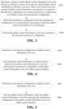
- FIG. 1 is a flowchart one of an uplink control information transmission method according to an embodiment of the present application. As shown in FIG. 1 , the method includes steps described below.
- step S102 a transmission configuration set corresponding to uplink control information to be sent is determined.
- step S104 a transmission configuration is selected from the transmission configuration set.
- step S106 the uplink control information to be sent is transmitted according to the selected transmission configuration.
- a transmission configuration set corresponding to uplink control information to be sent is determined, a transmission configuration is selected from the transmission configuration set, and the uplink control information to be sent is transmitted according to the selected transmission configuration, thereby solving the problem in the related art that it is impossible to guarantee both robustness and high transmission efficiency at the same time during information transmissions, and guaranteeing both robustness and high transmission efficiency at the same time.
- the step in which a transmission configuration set corresponding to uplink control information to be sent is determined includes: determining the transmission configuration set according to an information type of the uplink control information to be sent; determining the transmission configuration set according to an indication of downlink control signaling; or determining the transmission configuration set according to an uplink or downlink transmission mode.
- the step in which a transmission configuration is selected from the transmission configuration set includes: selecting the transmission configuration from the transmission configuration set according to the information type of the uplink control information to be sent; selecting the transmission configuration from the transmission configuration set according to the indication of the downlink control signaling; or selecting the transmission configuration from the transmission configuration set according to the uplink or downlink transmission mode.
- the downlink control signaling is physical layer signaling.
- the step in which a transmission configuration set corresponding to uplink control information to be sent is determined includes: determining the transmission configuration set according to a responded object, or selecting the transmission configuration according to times of retransmission; or when the uplink control information to be sent includes channel state information (CSI), the step in which a transmission configuration set corresponding to uplink control information to be sent is determined includes: determining the transmission configuration set according to a type of the CSI.
- CSI channel state information
- the step in which a transmission configuration is selected from the transmission configuration set includes: selecting the transmission configuration according to the responded object, or selecting the transmission configuration according to times of retransmission; or in determination of the transmission configuration set according to the type of the CSI, the step in which a transmission configuration is selected from the transmission configuration set includes: selecting the transmission configuration according to the type of the CSI.
- the uplink control information includes at least one of: a response message, a scheduling request message, CSI, sending manner switching request information, receiving manner switching feedback information, or indication information of information reporting mode.
- the configuration in the transmission configuration set includes at least one of: at least one configuration of numerology, at least one configuration of sending code sequence set, at least one configuration of sending power, at least one configuration of sending times, at least one configuration of sending resource quantity, at least one configuration of sending resource granularity, at least one configuration of modulation manner, at least one configuration of coding manner, at least one configuration of sending manner, at least one configuration of receiving manner, or at least one configuration of transmission area.
- the configuration of numerology includes at least one of: a time domain symbol length, a subcarrier spacing, a number of points in fast Fourier transform (FFT) algorithm, a subcarrier density, a cyclic prefix (CP) length, a frequency domain guard band, or a guard period (GP); and/or
- FFT fast Fourier transform
- CP cyclic prefix
- GP guard period
- FIG. 2 is a flowchart two of an uplink control information transmission method according to an embodiment of the present application. As shown in FIG. 2 , the method includes steps described below.
- step S202 a candidate transmission area set corresponding to uplink control information to be set is determined, where the candidate transmission area set at least includes a number M of transmission areas, and M is an integer greater than 1.
- step S204 a number N of transmission areas are selected from a transmission configuration set, where N is greater than or equal to 1 and is less than or equal to M, and N is an integer.
- step S206 the uplink control information to be sent is transmitted according to the N selected transmission areas.
- a candidate transmission area set corresponding to uplink control information to be set is determined, where the candidate transmission area set at least includes a number M of transmission areas, and M is an integer greater than 1; a number N of transmission areas are selected from a transmission configuration set, where N is greater than or equal to 1 and is less than or equal to M, and N is an integer; and the uplink control information to be sent is transmitted according to the N selected transmission areas, thereby solving the problem in the related art that it is impossible to guarantee both robustness and high transmission efficiency at the same time during information transmissions, and guaranteeing both robustness and high transmission efficiency at the same time.
- the M transmission areas at least include an area i and an area j,
- the uplink control information includes at least one of: a response message, a scheduling request message, channel state information (CSI), sending manner switching request information, receiving manner switching feedback information, or indication information of information reporting mode.
- CSI channel state information
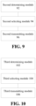
- FIG. 3 is a flowchart three of an uplink control information transmission method according to an embodiment of the present application. As shown in FIG. 3 , the method includes steps described below.
- a group to which uplink control information to be sent belongs is determined according to at least one group into which uplink control information is divided in advance, where each of the at least one group of uplink control information corresponds to a respective transmission configuration set, and the transmission configuration set includes at least one transmission configuration.
- step S304 the transmission configuration is selected from the transmission configuration set corresponding to the group to which the uplink control information to be sent belongs.
- step S306 the uplink control information to be sent is transmitted according to the selected transmission configuration.
- a group to which uplink control information to be sent belongs is determined according to at least one group into which uplink control information is divided in advance, where each of the at least one group of uplink control information corresponds to a respective transmission configuration set, and the transmission configuration set includes at least one transmission configuration; the transmission configuration is selected from the transmission configuration set corresponding to the group to which uplink control information to be sent belongs; and the uplink control information to be sent is transmitted according to the selected transmission configuration, thereby solving the problem in the related art that it is impossible to guarantee both robustness and high transmission efficiency at the same time during information transmissions, and guaranteeing both robustness and high transmission efficiency at the same time.
- the method further includes: dividing the information into a number X of groups according to a type of the uplink control information, where X is an integer greater than or equal to 1.
- the uplink control information includes at least one of: a response message, a scheduling request message, channel state information (CSI), sending manner switching request information, receiving manner switching feedback information, or indication information of information reporting mode.
- CSI channel state information
- the CSI at least includes: a channel quality indicator/index (CQI), a precoding matrix indicator (PMI), a rank indicator (RI) of a channel, a channel state information reference signal resource indicator/index (CRI), port selection information, and a beam indicator/index (BI).
- CQI channel quality indicator/index
- PMI precoding matrix indicator
- RI rank indicator
- CRI channel state information reference signal resource indicator/index
- BI beam indicator/index
- BI beam indicator/index
- the first group of the two group includes at least one of: the scheduling request message, the response message, the BI, the CRI, the RI, the sending manner switching request information, the receiving manner switching feedback information, or the indication information of information reporting mode, and a second group includes at least one of: the CQI or the PMI; or
- sending power corresponding to the second group is less than or equal to sending power corresponding to the first group
- the sending sector of the second group is a subset of the sending sector of the first group.
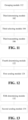
- FIG. 4 is a flowchart one of an uplink control information transmission configuration indication method according to an embodiment of the present application. As shown in FIG. 4 , the method includes steps described below.
- step S402 a transmission configuration of uplink control information to be sent is determined.
- step S404 downlink control information is sent at a physical layer, where the downlink control information is used for indicating the transmission configuration of the uplink control information to be sent within a preset duration.
- the transmission configuration includes at least one of: a configuration of numerology, a configuration of sending code sequence set, a configuration of sending power, a configuration of sending times, a configuration of sending resource quantity, a configuration of sending resource granularity, a configuration of modulation manner, a configuration of coding manner, a configuration of sending manner, a configuration of receiving manner, or a configuration of transmission area.
- the configuration of numerology includes at least one of: a time domain symbol length, a subcarrier spacing, a number of points in fast Fourier transform (FFT) algorithm, a subcarrier density, a cyclic prefix (CP) length, a frequency domain guard band, or a guard period (GP); and/or
- FFT fast Fourier transform
- CP cyclic prefix
- GP guard period
- the uplink control information includes at least one of: a response message, a scheduling request message, channel state information (CSI), sending manner switching request information, receiving manner switching feedback information, or indication information of information reporting mode.
- CSI channel state information
- FIG. 5 is a flowchart two of an uplink control information transmission configuration indication method according to an embodiment of the present application. As shown in FIG. 5 , the method includes steps described below.
- step S502 a transmission configuration of uplink control information to be sent is determined.
- step S504 the uplink control information is sent, where the uplink control information is used for indicating the transmission configuration of the uplink control information to be sent within a preset duration.
- the transmission configuration includes at least one of: a configuration of numerology, a configuration of sending code sequence set, a configuration of sending power, a configuration of sending times, a configuration of sending resource quantity, a configuration of sending resource granularity, a configuration of modulation manner, a configuration of coding manner, a configuration of sending manner, a configuration of receiving manner, or a configuration of transmission area.
- the configuration of numerology includes at least one of: a time domain symbol length, a subcarrier spacing, a number of points in fast Fourier transform (FFT) algorithm, a subcarrier density, a cyclic prefix (CP) length, a frequency domain guard band, or a guard period (GP);
- FFT fast Fourier transform
- CP cyclic prefix
- GP guard period
- the uplink control information includes at least one of: a response message, a scheduling request message, channel state information (CSI), sending manner switching request information, receiving manner switching feedback information, or indication information of information reporting mode.
- CSI channel state information
- a terminal For the uplink, a terminal needs to feed back some information unknown to a base station to the base station and some request messages initiated by the terminal, such as following types of information: the response message, the scheduling request message and the CSI.
- the response message mainly includes states such as acknowledgement (ACK) and negative acknowledgement (NACK), and is used as a response to control information or a data block which has been previously sent.
- ACK acknowledgement
- NACK negative acknowledgement
- the ACK is fed back when the data block is received and decoded correctly
- the NACK is fed back when the data block is received but decoded incorrectly
- nothing is fed back when no data block is received.
- the control information there are three situations. In the first situation, which is the same as the data block, the ACK is fed back when the control information is received and decoded correctly; and the NACK is fed back when the control information is received but decoded incorrectly. In the second situation, the ACK is fed back only when the control information is received and decoded correctly; otherwise, nothing is fed back. In the third situation, the NACK is fed back only when the control information is received but decoded incorrectly; otherwise, nothing is fed back.
- the scheduling request message is mainly used for UE to initiate a scheduling request to the base station.
- the CSI is a general term and includes various types of CSI, such as quantization information of a matrix of a channel, quantization information of feature vectors of the channel, a channel quality indicator/index (CQI), interference measurement, a precoding matrix indicator (PMI), a rank indicator (RI) of the channel, feedback information of the number of precoding layers, a channel state information reference signal resource indicator/index (CRI), port selection information, indication information of a measurement resource location, and a beam indicator/index (BI).
- CQI channel quality indicator/index
- the sending manner switching request information is mainly used by the terminal to request the base station to switch the sending manner, and the sending manner includes a sending node, a sending beam, a transmission technology, a sending antenna, a sending sector, etc.
- the receiving manner switching feedback information is mainly used by the terminal to notify the base station to switch the receiving manner, and the receiving manner includes a receiving beam, a receiving antenna, a receiving sector, etc.
- the indication information of information reporting mode is mainly used for indicating subsequent information reporting content.
- FIG. 6 is a block diagram one of an uplink control information transmission device according to an embodiment of the present application. As shown in FIG. 6 , the device includes a first determining module 62, a first selecting module 64 and a first transmitting module 66.
- the first determining module 62 is configured to determine a transmission configuration set corresponding to uplink control information to be sent.
- the first selecting module 64 is configured to select a transmission configuration from the transmission configuration set.
- the first transmitting module 66 is configured to transmit the uplink control information to be sent according to the selected transmission configuration.
- FIG. 7 is a block diagram one of an uplink control information transmission device according to a preferred embodiment of the present application.
- the first determining module 62 includes a first determining unit 72.
- the first determining unit 72 is configured to determine the transmission configuration set according to an information type of the uplink control information to be sent; determine the transmission configuration set according to an indication of downlink control signaling; or determine the transmission configuration set according to an uplink or downlink transmission mode.
- the first determining unit 64 is further configured to, when the transmission configuration set includes a plurality of transmission configurations, select the transmission configuration from the transmission configuration set according to the information type of the uplink control information to be sent; select the transmission configuration from the transmission configuration set according to the indication of the downlink control signaling; or select the transmission configuration from the transmission configuration set according to the uplink or downlink transmission mode.
- FIG. 8 is a block diagram two of an uplink control information transmission device according to a preferred embodiment of the present application. As shown in FIG. 8 , the first determining module 62 includes a second determining unit 82.
- the second determining unit 82 is configured to, when the uplink control information to be sent comprises response information, determine the transmission configuration set according to a responded object, or select the transmission configuration according to times of retransmission; or when the uplink control information to be sent comprises channel state information (CSI), determine the transmission configuration set according to a type of the CSI.
- CSI channel state information
- the first selecting module 64 is further configured to, in determination of the transmission configuration set according to the responded object, select the transmission configuration according to the responded object; or in determination of the transmission configuration set according to the type of the CSI, the selecting a transmission configuration from the transmission configuration set includes: selecting the transmission configuration according to the type of the CSI.
- FIG. 9 is a block diagram two of an uplink control information transmission device according to an embodiment of the present application. As shown in FIG. 7 , the device includes a second determining module 92, a second selecting module 94 and a second transmitting module 96.
- the second determining module 92 is configured to determine a candidate transmission area set corresponding to uplink control information to be set, where the candidate transmission area set at least includes a number M of transmission areas, and M is an integer greater than 1.
- the second selecting module 94 is configured to select a number N of transmission areas from a transmission configuration set, where N is greater than or equal to 1 and is less than or equal to M, and N is an integer.
- the second transmitting module 96 is configured to transmit the uplink control information to be sent according to the N selected transmission configuration.
- the M transmission areas at least include an area i and an area j,
- the third determining module 102 is configured to determine a group to which uplink control information to be sent belongs according to at least one group into which uplink control information is divided in advance, where each of the at least one group of uplink control information corresponds to a respective transmission configuration set, and the transmission configuration set includes at least one transmission configuration.
- the third selecting module 104 is configured to select the transmission configuration from the transmission configuration set corresponding to the group to which the uplink control information to be sent belongs.
- the third transmitting module 106 is configured to transmit the uplink control information to be sent according to the selected transmission configuration.
- FIG. 11 is a block diagram three of an uplink control information transmission device according to a preferred embodiment of the present application. As shown in FIG. 11 , the device includes a grouping unit 112.
- the grouping module 112 is configured to divide the uplink control information into two groups.
- a first group of the two group includes at least one of: the scheduling request message, the response message, the BI, the CRI, the RI, the sending manner switching request information, the receiving manner switching feedback information, or the indication information of information reporting mode, and a second group includes at least one of: the CQI or the PMI; or
- FIG. 12 is a block diagram one of an uplink control information transmission configuration indication device according to an embodiment of the present application. As shown in FIG. 12 , the device includes a fourth determining module 122 and a first sending module 124. The fourth determining module 122 is configured to determine a transmission configuration of uplink control information to be sent.
- the first sending module 124 is configured to send downlink control information at a physical layer, where the downlink control information is used for indicating the transmission configuration of the uplink control information to be sent within a preset duration.
- the transmission configuration includes at least one of: a configuration of numerology, a configuration of sending code sequence set, a configuration of sending power, a configuration of sending times, a configuration of sending resource quantity, a configuration of sending resource granularity, a configuration of modulation manner, a configuration of coding manner, a configuration of sending manner, a configuration of receiving manner, or a configuration of transmission area.
- FIG. 13 is a block diagram two of an uplink control information transmission configuration indication device according to an embodiment of the present application. As shown in FIG. 13 , the device includes a fifth determining module 132 and a second sending module 134. The fifth determining module 132 is configured to determine a transmission configuration of uplink control information to be sent.
- the second sending module 134 is configured to send uplink control information, where the uplink control information is used for indicating the transmission configuration of the uplink control information to be sent within a preset duration.
- the transmission configuration includes at least one of: a configuration of numerology, a configuration of sending code sequence set, a configuration of sending power, a configuration of sending times, a configuration of sending resource quantity, a configuration of sending resource granularity, a configuration of modulation manner, a configuration of coding manner, a configuration of sending manner, a configuration of receiving manner, or a configuration of transmission area.
- FIG. 14 is a schematic diagram of a terminal according to an embodiment of the present application. As shown in FIG. 14 , the terminal includes a processor 1402 and a memory 1404 storing processor-executable instructions which, when executed by the processor, execute following operations:
- the processor is configured to further execute the following operations: determining the transmission configuration set according to an information type of the uplink control information to be sent; determining the transmission configuration set according to an indication of downlink control signaling; or determining the transmission configuration set according to an uplink or downlink transmission mode.
- FIG. 15 is a schematic diagram of a base station according to an embodiment of the present application.
- the base station includes a processor 1502 and a memory 1504 storing processor-executable instructions which, when executed by the processor, execute following operations:
- the transmission configuration includes at least one of: a configuration of numerology, a configuration of sending code sequence set, a configuration of sending power, a configuration of sending times, a configuration of sending resource quantity, a configuration of sending resource granularity, a configuration of modulation manner, a configuration of coding manner, a configuration of sending manner, a configuration of receiving manner, or a configuration of transmission area.
- This embodiment further provides a terminal, which includes a processor and a memory storing processor-executable instructions which, when executed by the processor, execute following operations:
- the transmission configuration includes at least one of: a configuration of numerology, a configuration of sending code sequence set, a configuration of sending power, a configuration of sending times, a configuration of sending resource quantity, a configuration of sending resource granularity, a configuration of modulation manner, a configuration of coding manner, a configuration of sending manner, a configuration of receiving manner, or a configuration of transmission area.
- This embodiment further provides a storage medium.
- the storage medium may be configured to store program codes for executing steps described below.
- step S11 a transmission configuration set corresponding to uplink control information to be sent is determined.
- step S12 a transmission configuration is selected from the transmission configuration set.
- step S13 the uplink control information to be sent is transmitted according to the selected transmission configuration.
- the storage medium may be configured to store program codes for executing steps described below.
- step S21 a candidate transmission area set corresponding to uplink control information to be set is determined, where the candidate transmission area set at least includes a number M of transmission areas, and M is an integer greater than 1.
- N transmission areas is selected from a transmission configuration set, where N is greater than or equal to 1 and is less than or equal to M, and N is an integer.
- step S23 the uplink control information to be sent is transmitted according to the N selected transmission areas.
- the storage medium may be configured to store program codes for executing steps described below.
- a group to which uplink control information to be sent belongs is determined according to at least one group into which uplink control information is divided in advance, where each of the at least one group of uplink control information corresponds to a respective transmission configuration set, and the transmission configuration set includes at least one transmission configuration.
- step S32 the transmission configuration is selected from the transmission configuration set corresponding to the group to which the uplink control information to be sent belongs.
- step S33 the uplink control information to be sent is transmitted according to the selected transmission configuration.
- the storage medium described above may include, but is not limited to, a USB flash disk, a read-only memory (ROM), a random access memory (RAM), a mobile hard disk, a magnetic disk, an optical disk or another medium capable of storing program codes.
- a first type of information is determined.
- the first type of information includes: a response message, a scheduling request message, channel state information (CSI), sending manner switching request information, receiving manner switching feedback information, and indication information of information reporting mode, which are mentioned above.
- CSI channel state information
- the terminal needs to determine the content of information which needs to be reported according to a current feedback mode, trigger signaling of the base station, and agreement between the terminal and the base station.
- there may be only one type of the first type of information which needs to be reported or there may be multiple types of the first type of information which need to be reported.
- these types of the first type of information may be combined and reported, or may be reported separately.
- step 102 a transmission configuration set corresponding to the first type of information is determined.
- the first type of information may correspond to different transmission configuration sets.
- the transmission configuration in the transmission configuration set is used for transmitting the first type of information. Specific parameter types included in the transmission configuration will be described in the embodiments hereafter.
- One manner is to achieve an agreement on the transmission configuration set corresponding to the first type of information in advance; and another manner is to require configuration signaling of the base station to configure the transmission configuration set. If the base station has sent configuration set indication signaling, the terminal needs to determine the transmission configuration set according to the configuration set indication signaling. Different terminals may configure different transmission configuration sets. Since different uplink or downlink transmission modes may correspond to different agreements or configurations of the transmission configuration set, regardless of the manner of agreement in advance or the manner requiring the indication of the signaling of the base station, the terminal needs to determine the transmission configuration set in conjunction with the uplink or downlink transmission mode.
- information types included in different first type of information may correspond to agreements or configurations of different transmission configuration sets, regardless of the manner of agreement in advance or the manner requiring the indication of the signaling of the base station, the terminal needs to determine the transmission configuration set in conjunction with the information type included in the first type of information.
- the first type of information is the response message
- response messages directed to different responded objects should be considered as different types.
- the response message for data and the response message for control may correspond to different transmission configuration sets.
- the first type of information is the CSI
- different sub-types of the CSI should be considered as different types.
- the CRI, the RI, the PMI and the CQI may correspond to different transmission configuration sets.
- the transmission configuration set for the case where the responded object is first transmitted data may be different from the transmission configuration set for the case where the responded object is retransmitted data. Therefore, regardless of the manner of agreement in advance or the manner requiring the indication of the signaling of the base station, the terminal needs to determine the transmission configuration set in conjunction of whether the data, to which the response message is responsive, is first transmitted or retransmitted, as well as how many times the data has been retransmitted.
- the better different transmission configuration sets may be different, so that different sets may be determined in advance according to features of various types of the first type of information.
- extreme importance and information of low sending frequency may take a transmission configuration with high robustness; and information of ordinary importance may take a transmission configuration with relatively high robustness and a transmission configuration with relatively high transmission efficiency.
- higher the robustness is, more resources are required for transmitting information.
- the resources include time domain resources, frequency domain resources, spatial domain resources, a code domain resources and power.
- the high transmission efficiency means that the information is transmitted successfully by using fewer resources.
- step 103 a transmission configuration is selected from the transmission configuration set.
- the terminal needs to select the transmission configuration in the transmission configuration set according to the configuration selection indication signaling.
- the signaling is preferably physical layer control signaling, which allows to quickly switch between configurations and to flexibly select the transmission configuration in the transmission configuration set.
- the terminal may autonomously and flexibly select the transmission configuration. Different terminals may select different transmission configurations in the transmission configuration set. Alternatively, the terminal may select the transmission configuration according to the transmission mode, the information type included in the first type of information, the responded object and retransmission times of response information. Different transmission configurations in the transmission configuration set may be selected for different uplink or downlink transmission modes. Different transmission configurations in the transmission configuration set may be selected for different information types included in the first type of information.
- response messages directed to different responded objects should be considered as different types.
- the response message for data and the response message for the control may correspond to different transmission configuration selection.
- the first type of information is the CSI
- different sub-types of the CSI should be considered as different types.
- the CRI, the RI, the PMI and the CQI may correspond to different transmission configuration selection.
- the transmission configuration selected for the case where the responded object is first transmitted data may be different from the transmission configuration selected for the case where the responded object is retransmitted data. Therefore, regardless of the manner of agreement in advance or the manner requiring the indication of the signaling of the base station, the terminal needs to determine the transmission configuration selection in conjunction of whether the responded data is first transmitted or retransmitted, as well as how many times the data has been retransmitted. If the corresponding transmission configuration set includes only one transmission configuration, this transmission configuration is directly used. In step 104, the first type of information is transmitted according to the selected transmission configuration.
- the terminal determines the transmission configuration set according to the information type included in the first type of information. Specific transmission configuration types are described in the subsequent embodiments. For specific manner for determining this set in this embodiment, reference may be made to the manner described in the embodiment 1.
- Table 2 Scheduling request message Transmission configuration 11, transmission configuration 12 Response message of the control information Transmission configuration 21, transmission configuration 22 Response message of the data information Transmission configuration 31, transmission configuration 32 Sending manner switching request information Transmission configuration 41, transmission configuration 42 Receiving manner switching request information Transmission configuration 51, transmission configuration 52 Indication information of information reporting mode Transmission configuration 61, transmission configuration 62
- one type of the first type of information corresponds to multiple configurations.
- one type of the first type of information may correspond to only one configuration.
- part of the type of the first type of information corresponds to only one configuration, and part of the type of the first type of information corresponds to multiple configurations.
- each of groups into which the first type of information is grouped corresponds to one transmission configuration set.
- the first preferable grouping manner is that a first group includes at least one of the scheduling request message, the response message, the BI, the CRI, the RI, the sending manner switching request information, the receiving manner switching request information, or the indication information of information reporting mode, and a second group includes at least one of: the CQI or the PMI, as shown in Table 3.
- Table 3 Group 1 of the first type of information At least one of the response message, the BI, the CRI, the RI, the sending manner switching request information, the receiving manner switching request information, or the indication information of information reporting mode
- Group 2 of the first type of information At least one of the CQI or the PMI
- the grouping manner at this time is as shown in Table 4.
- Table 4 Group 1 of the first type of information At least one of the response message, the BI, the CRI, the RI, the sending manner switching request information, the receiving manner switching request information, the indication information of information reporting mode, or the first PMI Group 2 of the first type of information At least one of the CQI or a second PMI
- the second preferable grouping manner is that the first group includes at least one of the scheduling request message, the response message, the sending manner switching request information, the receiving manner switching request information, or the indication information of information reporting mode, and the second group includes at least one of pieces of the CSI, as shown in Table 5.
- Table 5 Group 1 of the first type of information At least one of the scheduling request message, the response message, the sending manner switching request information, the receiving manner switching request information, or the indication information of information reporting mode
- Group 2 of the first type of information At least one of pieces of the CSI
- the third preferable grouping manner is that the first group includes at least one of the scheduling request message, the sending manner switching request information, the receiving manner switching request information, or the indication information of information reporting mode, and the second group includes at least one of the response message or the CSI, as shown in Table 6.
- Table 6 Group 1 of the first type of information The scheduling request message, the sending manner switching request information, the receiving manner switching request information, and the indication information of information reporting mode Group 2 of the first type of information
- a manner for grouping more groups may also be easily extended.
- Some information with similar importance and sending frequency may be grouped into one group.
- Each group may correspond to one transmission configuration set.
- One transmission configuration includes one or more set of transmission configurations.
- Different groups may correspond to different transmission configuration sets due to its different characteristics.
- This embodiment is mainly used for describe some configuration types included in the transmission configuration. These configuration types mainly include: at least one configuration of numerology.
- basic transmission parameters mainly include following classifications: a time domain symbol length, the number of subcarriers, a subcarrier spacing, a frequency domain guard band, a cyclic prefix (CP), a time domain guard period (GP), and the number of points in fast Fourier transform (FFT) algorithm.
- the time domain signal length refers to an OFDM symbol length.
- Modulation symbols are carried on M OFDM subcarriers. Modulation symbols are carried on M OFDM subcarriers, these subcarriers constitute a time domain sample point after transformed to the time domain, and the time domain sample point and the guard period form a time domain OFDM symbol.
- the OFDM symbol length is related to the number and spacing of subcarriers in the frequency domain. That is, with the same bandwidth, the larger the number of subcarriers is and the smaller the subcarrier spacing is, the longer the OFDM symbol length is, which may be described as that with the same subcarrier spacing, the larger the number of subcarriers is, the longer the OFDM symbol length is, and vice versa.
- the number of subcarriers refers to the number of subcarriers carrying the modulation symbols in the frequency domain corresponding to the same one OFDM symbol.
- the subcarrier spacing refers to the spacing of center frequencies between the subcarriers.
- the frequency domain guard band refers to that some bandwidths on both sides are generally reserved as guard bands during the information transmission. For example, in the current LTE system with 20 MHz bandwidth, actually only 100 resource blocks (RBs) are used, and only 1200 subcarriers, that is, total 18 MHz bandwidth, are occupied, which means that 2 MHz guard bands are reserved.
- the guard bands are generally on both sides of the bandwidth and mainly used for avoiding impact of out-of-band emission on performance when other wireless communication systems send information.
- the CP generally refers to some prefixes added in the front of some time domain sample points formed after the frequency domain signals are transformed into the time domain.
- the prefixes generally are copies of latter part of sample points of a string of time domain sample points. For example, a series of signals 0, 1, 2, 3, 4, 5, 6, 7, 8 and 9 to which a cyclic prefix with a length of 4 is added are signals 6, 7, 8, 9, 0, 1, 2, 3, 4, 5, 6, 7, 8 and 9.
- guard period For the time domain guard period (GP), during radio frequency (RF) precoding, switching from one precoding to another precoding requires certain processing time, so that similar guard periods are also required. Although some other places also have similar concepts of the guard period, various guard periods in the present application are all considered as one type of basic transmission parameters.
- the number of points in fast Fourier transform (FFT) algorithm is generally related to the number of subcarriers and the bandwidth, but is not completely equal to the number of active subcarriers. For example, for a 20 MHz/10 MHz LTE system, in 2048 points and 1024 points are adopted respectively, the number of active subcarriers is just 1200 and 600 respectively.
- FFT fast Fourier transform
- one or more sets of numerology parameters may be adopted.
- the type of basic parameter configuration included in each set may be one or more types mentioned above. The following are the types of configuration mentioned above:
- step 201 a first type of information is determined.
- the first type of information includes: a response message, a scheduling request message, channel state information (CSI), sending manner switching request information, receiving manner switching feedback information, and indication information of information reporting mode, which are mentioned above.
- CSI channel state information
- the terminal needs to determine the content of information which needs to be reported according to a current feedback mode, trigger signaling of the base station, and some agreements with the base station.
- there may be only one type of the first type of information which needs to be reported or there may be various types of the first type of information which needs to be reported.
- various types of information need to be reported, they may be combined and reported, or may be reported separately.
- step 202 a candidate transmission area set corresponding to the first type of information is determined.
- the candidate transmission area set at least includes a number M of transmission areas, where M is an integer greater than 1.
- This transmission area set may be appointed in advance or may be configured. Since the transmission area set is also a type of representation form of the transmission area set, reference may be made to the embodiment 1.
- the transmission area is also a type of transmission configuration, reference may be made to the Embodiment.
- step 204 the first type of information is transmitted in the N selected transmission areas.
- the M transmission areas at least include an area i and an area j, and for transmission in the area i and the area j, a sending power offset P exists between the area i and the area j, where the sending power offset P is configured by a base station.
- the M transmission areas at least include an area i and an area j, and for transmission in the area i and the area j, a sending beam used for the area i is a subset of a sending beam used for the area j, a sending antenna used for the area i is a subset of a sending antenna used for the area j, a sending sector used for the area i is a subset of a sending sector used for the area j, a receiving beam used for the area i is a subset of a receiving beam used for the area j, a receiving antenna used for the area i is a subset of a receiving antenna used for the area j, a receiving sector used for the area i is a subset of a receiving sector used for the area j, a length of a cyclic prefix (CP) of an orthogonal frequency division multiplexing (OFDM) symbol
- CP cyclic prefix
- OFDM orthogonal frequency division multiplexing
- the M transmission areas at least include an area i and an area j, and for transmission in the area i and the area j, a time domain symbol corresponding to the area i is a subset of a time domain symbol corresponding to the area j, a resource block occupied by the area i is a subset of a resource block occupied by the area j, or the area i and the area j use different numerology parameters, where the different numerology parameters include at least one of: different time domain symbol lengths, different subcarrier spacings, different subcarrier densities, different CP lengths, different frequency domain guard bands, or different guard periods (GPs).
- the different numerology parameters include at least one of: different time domain symbol lengths, different subcarrier spacings, different subcarrier densities, different CP lengths, different frequency domain guard bands, or different guard periods (GPs).
- the M transmission areas correspond to M subframe sets configured by the base station, or the M transmission areas correspond to M resource block sets configured by the base station.
- a first type of information is divided into M groups according to information types, where each group of the first type of information corresponds to a respective transmission configuration set, the transmission configuration set includes at least one transmission configuration, and M is an integer greater than or equal to 1.
- step 302 a group to which the first type of information to be sent belongs is determined, a transmission configuration is selected from the transmission configuration set corresponding to this group.
- step 303 the first type of information is sent according to the selected transmission configuration.
- sending power corresponding to the second group is less than or equal to sending power corresponding to the first group
- a number of sending sectors corresponding to the second group is less than or equal to a number of sending sectors corresponding to the first group
- a sending sector of the second group is a subset of a sending sector of the first group
- a number of sending antennas corresponding to the second group is less than or equal to a number of sending antennas corresponding to the first group
- a sending antenna of the second group is a subset of a sending antenna of the first group
- a number of sending beams corresponding to the second group is less than or equal to a number of sending beams corresponding to the first group
- a sending beam of the second group is a subset of a sending beam of the first group
- a sending bandwidth of the second group is less than or equal to a sending bandwidth
- This embodiment describes a configuration method in which a base station sends a first type of information.
- the first type of information include at least one of: a response message, a scheduling request message, CSI information, sending manner switching request information, receiving manner switching feedback information or indication information of information reporting mode.
- the base station determines a transmission configuration of the first type of information according to current link transmission quality or according to both importance and robustness requirements of the first type of information.
- the base station may send downlink control information at a physical layer.
- the downlink control information is used for indicating the transmission configuration selection of the uplink first type of information within a period of time.
- This embodiment describes a configuration method in which the terminal selects and sends the first type of information, and notifies that to the base station.
- the first type of information include at least one of: a response message, a scheduling request message, CSI, sending manner switching request information, receiving manner switching feedback information or indication information of information reporting mode.
- the terminal may determine a transmission configuration of the first type of information according to current link transmission quality or according to both importance and robustness requirements of the first type of information.
- the terminal may send uplink control information at a physical layer.
- the uplink physical layer control information is used for indicating the transmission configuration selection of the uplink first type of information within a period of time.
- the uplink first type of information may adopt a transmission configuration different from that of the other uplink control information and the transmission configuration may be appointed in advance.
- each of the above-mentioned modules or steps of the present application may be implemented by a general-purpose computing device, the modules or steps may be concentrated on a single computing device or distributed on a network composed of multiple computing devices, and alternatively, the modules or steps may be implemented by program codes executable by the computing devices, so that the modules or steps may be stored in a storage device and executable by the computing devices.
- the illustrated or described steps may be executed in sequences different from those described herein, or the modules or steps may be made into various integrated circuit modules separately, or multiple modules or steps therein may be made into a single integrated circuit module for implementation. In this way, the present application is not limited to any specific combination of hardware and software.
- the present application relates to communications.
- a transmission configuration set corresponding to uplink control information to be sent is determined, a transmission configuration is selected from the transmission configuration set, and the uplink control information to be sent is transmitted according to the selected transmission configuration, thereby solving the problem in the related art that it is impossible to guarantee both robustness and high transmission efficiency at the same time during information transmissions, and guaranteeing both robustness and high transmission efficiency at the same time.
Landscapes
- Engineering & Computer Science (AREA)
- Signal Processing (AREA)
- Computer Networks & Wireless Communication (AREA)
- Physics & Mathematics (AREA)
- Mathematical Physics (AREA)
- Quality & Reliability (AREA)
- Discrete Mathematics (AREA)
- General Physics & Mathematics (AREA)
- Mobile Radio Communication Systems (AREA)
Applications Claiming Priority (3)
| Application Number | Priority Date | Filing Date | Title |
|---|---|---|---|
| CN201610877956.9A CN107889247B (zh) | 2016-09-30 | 2016-09-30 | 上行控制信息传输/配置指示方法、装置、终端及基站 |
| PCT/CN2017/103690 WO2018059444A1 (zh) | 2016-09-30 | 2017-09-27 | 上行控制信息传输/配置指示方法、装置、终端及基站 |
| EP17854894.7A EP3522414B1 (de) | 2016-09-30 | 2017-09-27 | Uplink-steuerungsinformation-übertragungs-/-konfigurationsanzeigeverfahren und vorrichtung, endgerät und basisstation |
Related Parent Applications (1)
| Application Number | Title | Priority Date | Filing Date |
|---|---|---|---|
| EP17854894.7A Division EP3522414B1 (de) | 2016-09-30 | 2017-09-27 | Uplink-steuerungsinformation-übertragungs-/-konfigurationsanzeigeverfahren und vorrichtung, endgerät und basisstation |
Publications (2)
| Publication Number | Publication Date |
|---|---|
| EP4560952A2 true EP4560952A2 (de) | 2025-05-28 |
| EP4560952A3 EP4560952A3 (de) | 2025-08-13 |
Family
ID=61763146
Family Applications (2)
| Application Number | Title | Priority Date | Filing Date |
|---|---|---|---|
| EP25169548.2A Pending EP4560952A3 (de) | 2016-09-30 | 2017-09-27 | Verfahren und vorrichtung zur übertragung/konfiguration von uplink-steuerungsinformationen, endgerät und basisstation |
| EP17854894.7A Active EP3522414B1 (de) | 2016-09-30 | 2017-09-27 | Uplink-steuerungsinformation-übertragungs-/-konfigurationsanzeigeverfahren und vorrichtung, endgerät und basisstation |
Family Applications After (1)
| Application Number | Title | Priority Date | Filing Date |
|---|---|---|---|
| EP17854894.7A Active EP3522414B1 (de) | 2016-09-30 | 2017-09-27 | Uplink-steuerungsinformation-übertragungs-/-konfigurationsanzeigeverfahren und vorrichtung, endgerät und basisstation |
Country Status (5)
| Country | Link |
|---|---|
| US (3) | US11051282B2 (de) |
| EP (2) | EP4560952A3 (de) |
| CN (2) | CN107889247B (de) |
| ES (1) | ES3035976T3 (de) |
| WO (1) | WO2018059444A1 (de) |
Families Citing this family (13)
| Publication number | Priority date | Publication date | Assignee | Title |
|---|---|---|---|---|
| JP7027892B2 (ja) | 2016-02-03 | 2022-03-02 | ソニーグループ株式会社 | 端末装置および通信方法 |
| CN107889247B (zh) * | 2016-09-30 | 2022-12-30 | 中兴通讯股份有限公司 | 上行控制信息传输/配置指示方法、装置、终端及基站 |
| CN108024268B (zh) * | 2016-11-03 | 2023-04-18 | 中兴通讯股份有限公司 | 一种传输配置方法、传输配置确定方法、基站和终端 |
| US10123322B1 (en) * | 2017-09-18 | 2018-11-06 | Qualcomm Incorporated | Transmission of beam switch commands through control channel signaling |
| US10582503B2 (en) * | 2017-11-10 | 2020-03-03 | Apple Inc. | UE initiated beam management procedure |
| WO2020060340A1 (ko) * | 2018-09-21 | 2020-03-26 | 엘지전자 주식회사 | 무선 통신 시스템에서 상향링크 송수신을 수행하기 위한 방법 및 이를 위한 장치 |
| CN109765825B (zh) * | 2019-01-30 | 2023-09-29 | 山西天科信息安全科技有限公司 | 一种物联网多链路安全控制终端和安全控制方法 |
| US11451992B2 (en) * | 2019-04-12 | 2022-09-20 | Qualcomm Incorporated | Beam preference feedback for data transmissions |
| WO2021012129A1 (zh) * | 2019-07-19 | 2021-01-28 | Oppo广东移动通信有限公司 | 一种信息传输方法及装置、通信设备 |
| US12237880B2 (en) * | 2019-09-13 | 2025-02-25 | Telefonaktiebolaget Lm Ericsson (Publ) | Arrangement and method performed therein for handling communication |
| CN113316253A (zh) * | 2020-02-27 | 2021-08-27 | 索尼公司 | 用于无线通信的电子设备和方法、计算机可读存储介质 |
| US11936452B2 (en) * | 2020-02-28 | 2024-03-19 | Qualcomm Incorporated | Neural network based channel state information feedback |
| US12368504B2 (en) * | 2022-05-17 | 2025-07-22 | Ast & Science, Llc | CPRI satellite communication system and method |
Family Cites Families (57)
| Publication number | Priority date | Publication date | Assignee | Title |
|---|---|---|---|---|
| EP2156629A4 (de) * | 2007-05-30 | 2016-03-23 | Lg Electronics Inc | Verfahren zur übertragung eines steuersignals in einem drahtlosen kommunikationssystem |
| US8630184B2 (en) * | 2007-08-15 | 2014-01-14 | Qualcomm Incorporated | Uplink control channel format |
| KR20100019947A (ko) * | 2008-08-11 | 2010-02-19 | 엘지전자 주식회사 | 무선 통신 시스템에서 정보 전송 방법 |
| MX2011001710A (es) * | 2008-08-12 | 2011-03-30 | Lg Electronics Inc | Metodo de transmision de datos en un sistema de portadores multiples y transmisor. |
| US20100067472A1 (en) * | 2008-08-15 | 2010-03-18 | Nokia Siemens Networks Oy | Backward compatible physical uplink control channel resource mapping |
| CN101478379A (zh) * | 2009-01-20 | 2009-07-08 | 中兴通讯股份有限公司 | 物理上行控制信道的发送方法及用户设备 |
| WO2011041623A1 (en) * | 2009-10-01 | 2011-04-07 | Interdigital Patent Holdings, Inc. | Uplink control data transmission |
| US20120113831A1 (en) * | 2010-04-30 | 2012-05-10 | Interdigital Patent Holdings, Inc. | Determination of Carriers and Multiplexing for Uplink Control Information Transmission |
| US20120113909A1 (en) * | 2010-05-06 | 2012-05-10 | Yu-Chih Jen | Method of Handling an Uplink Control Channel and Related Communication Device |
| CN102104972B (zh) * | 2010-05-24 | 2014-01-29 | 电信科学技术研究院 | Uci信息传输的配置方法和设备 |
| JP4852166B1 (ja) * | 2010-08-04 | 2012-01-11 | シャープ株式会社 | 移動局装置、通信システム、通信方法および集積回路 |
| US8670379B2 (en) * | 2010-10-02 | 2014-03-11 | Sharp Kabushiki Kaisha | Uplink control information multiplexing on the physical uplink control channel for LTE-A |
| CN102045827B (zh) * | 2011-01-06 | 2013-07-31 | 大唐移动通信设备有限公司 | 上行功率控制方法、功率控制参数配置方法及其装置 |
| CN102281593B (zh) | 2011-07-06 | 2014-09-10 | 电信科学技术研究院 | 上行控制信息发送及接收方法、系统和设备 |
| EP2764646B1 (de) * | 2011-10-04 | 2018-12-05 | Nokia Solutions and Networks Oy | Verfahren zum multiplexen von uplink-steuerinformationen |
| CN102412883B (zh) * | 2011-11-04 | 2017-07-07 | 中兴通讯股份有限公司 | 上行控制信息的发送方法和装置 |
| CN103167615B (zh) * | 2011-12-19 | 2016-03-02 | 华为技术有限公司 | 信息的处理方法及装置 |
| AU2013228185B2 (en) * | 2012-03-05 | 2016-11-03 | Samsung Electronics Co., Ltd. | HARQ-ACK signal transmission in response to detection of control channel type in case of multiple control channel types |
| US9072087B2 (en) * | 2012-03-28 | 2015-06-30 | Qualcomm Incorporated | Channel state information dependent ACK/NAK bundling |
| US9313779B2 (en) * | 2012-07-27 | 2016-04-12 | Intel Corporation | Uplink control information transmission with large number of bits |
| US9338768B2 (en) * | 2012-07-27 | 2016-05-10 | Intel Corporation | Uplink power control for physical uplink control channel |
| CN103580797B (zh) * | 2012-08-03 | 2017-05-03 | 电信科学技术研究院 | 上行控制信息uci的传输方法和设备 |
| US9544801B2 (en) * | 2012-08-03 | 2017-01-10 | Intel Corporation | Periodic channel state information reporting for coordinated multipoint (coMP) systems |
| TWI487408B (zh) * | 2012-11-01 | 2015-06-01 | Innovative Sonic Corp | 在無線通訊系統中處理上行鏈路資訊之方法 |
| EP3550897A1 (de) * | 2013-01-03 | 2019-10-09 | LG Electronics Inc. | Verfahren und vorrichtung zur übertragung von uplink-signalen in einem drahtloskommunikationssystem |
| US10361831B2 (en) * | 2013-04-16 | 2019-07-23 | Telefonaktiebolaget Lm Ericsson (Publ) | Wireless device and method for selecting uplink transmission parameters |
| CN105379391B (zh) * | 2013-08-05 | 2019-04-16 | 夏普株式会社 | 终端、基站以及通信方法 |
| CN104349443B (zh) * | 2013-08-09 | 2019-02-12 | 电信科学技术研究院 | 一种上行功率控制方法和装置 |
| KR102284453B1 (ko) * | 2014-01-29 | 2021-08-02 | 삼성전자 주식회사 | 셀룰러 이동 통신 시스템에서 상향링크 제어 정보 전송 방법 및 장치 |
| CN104853423A (zh) * | 2014-02-14 | 2015-08-19 | 上海朗帛通信技术有限公司 | 一种ue、基站中和多个服务小区连接的方法和设备 |
| US10142945B2 (en) * | 2014-06-05 | 2018-11-27 | Samsung Electronics Co., Ltd. | Power control for transmission of uplink control information on two cells in carrier aggregation |
| CN105323849B (zh) * | 2014-06-30 | 2020-04-07 | 中兴通讯股份有限公司 | 上行控制信道的配置和发送方法、装置及基站和用户设备 |
| US10687316B2 (en) * | 2014-07-17 | 2020-06-16 | Qualcomm Incorporated | Techniques for enabling component carriers for multi-carrier wireless communication |
| US9955356B2 (en) * | 2014-09-25 | 2018-04-24 | Intel IP Corporation | System and method of handling uplink transmission collision for enhanced coverage mode UEs |
| US10257853B2 (en) * | 2014-12-18 | 2019-04-09 | Qualcomm Incorporated | Techniques for identifying resources to transmit a channel reservation signal |
| US10425921B2 (en) * | 2015-04-01 | 2019-09-24 | Acer Incorporated | Method of uplink control information transmission |
| KR102316775B1 (ko) * | 2015-04-02 | 2021-10-26 | 삼성전자 주식회사 | 무선 셀룰라 통신 시스템에서 전송시간구간 감소를 위한 송수신 방법 및 장치 |
| US11641255B2 (en) * | 2015-04-05 | 2023-05-02 | Comcast Cable Communications, Llc | Uplink control information transmission in a wireless network |
| BR112017021599A2 (pt) * | 2015-04-09 | 2018-07-03 | Ericsson Telefon Ab L M | métodos de transmissão adaptativa para informação de controle de uplink |
| CN106257856B (zh) * | 2015-06-19 | 2021-02-02 | 北京三星通信技术研究有限公司 | 一种传输上行控制信息的方法 |
| WO2017026877A1 (ko) * | 2015-08-13 | 2017-02-16 | 엘지전자 주식회사 | 무선 통신 시스템에서 단말에 의해 수행되는 주기적 csi 보고 방법 및 상기 방법을 이용하는 단말 |
| US10547366B2 (en) * | 2015-09-04 | 2020-01-28 | Samsung Electronics Co., Ltd. | Method and apparatus for CSI reporting on PUCCH |
| EP3989466B1 (de) * | 2015-09-17 | 2024-03-20 | Apple Inc. | Übertragung von uplink-steuerungsinformationen in drahtlosen systemen |
| CN107889247B (zh) * | 2016-09-30 | 2022-12-30 | 中兴通讯股份有限公司 | 上行控制信息传输/配置指示方法、装置、终端及基站 |
| KR102385358B1 (ko) * | 2017-04-28 | 2022-04-11 | 엘지전자 주식회사 | 무선 통신 시스템에서 채널 상태 정보를 보고하기 위한 방법 및 이를 위한 장치 |
| EP4557648A3 (de) * | 2017-05-03 | 2025-09-03 | InterDigital Patent Holdings, Inc. | Verfahren, systeme und vorrichtung zur übertragung von uplink-steuerinformationen |
| JP2019004212A (ja) * | 2017-06-12 | 2019-01-10 | シャープ株式会社 | 基地局装置、端末装置およびその通信方法 |
| CN109474999B (zh) * | 2017-09-08 | 2024-08-13 | 华为技术有限公司 | 发送上行控制信道的方法和装置 |
| CN109495972A (zh) * | 2017-09-10 | 2019-03-19 | 株式会社Ntt都科摩 | 发送上行控制信息的方法和移动台 |
| EP3787189A1 (de) * | 2017-11-09 | 2021-03-03 | Comcast Cable Communications LLC | Csi-übertragung mit teilen mit mehreren bandbreiten |
| US11121825B2 (en) * | 2017-11-26 | 2021-09-14 | Qualcomm Incorporated | Mapping uplink control information to uplink data channel in wireless communication |
| CN110035535A (zh) * | 2018-01-12 | 2019-07-19 | 华为技术有限公司 | 一种上行控制信息的传输方法、接入网设备以及终端设备 |
| KR102745002B1 (ko) * | 2018-02-11 | 2024-12-19 | 광동 오포 모바일 텔레커뮤니케이션즈 코포레이션 리미티드 | 업링크 제어 정보를 전송하는 방법 및 기기 |
| KR20190129674A (ko) * | 2018-05-11 | 2019-11-20 | 삼성전자주식회사 | 무선 통신 시스템에서 이중 접속을 위한 단말의 상향 전송 전력 제어 방법 및 장치 |
| US20200036473A1 (en) * | 2018-07-24 | 2020-01-30 | Mediatek Singapore Pte. Ltd. | Uplink Control Information And Physical Uplink Control Channel Transmission Enhancement In Mobile Communications |
| KR102822959B1 (ko) * | 2019-05-02 | 2025-06-20 | 삼성전자 주식회사 | 무선 통신 시스템에서 이중 접속을 위한 단말의 상향 채널 전송 자원 결정 방법 및 장치 |
| WO2023056215A1 (en) * | 2021-09-30 | 2023-04-06 | Qualcomm Incorporated | Cross physical uplink control channel group channel state information report |
-
2016
- 2016-09-30 CN CN201610877956.9A patent/CN107889247B/zh active Active
- 2016-09-30 CN CN202211673179.8A patent/CN115866783A/zh active Pending
-
2017
- 2017-09-27 EP EP25169548.2A patent/EP4560952A3/de active Pending
- 2017-09-27 EP EP17854894.7A patent/EP3522414B1/de active Active
- 2017-09-27 US US16/335,940 patent/US11051282B2/en active Active
- 2017-09-27 ES ES17854894T patent/ES3035976T3/es active Active
- 2017-09-27 WO PCT/CN2017/103690 patent/WO2018059444A1/zh not_active Ceased
-
2021
- 2021-05-26 US US17/330,799 patent/US11791930B2/en active Active
-
2023
- 2023-09-20 US US18/370,421 patent/US12273190B2/en active Active
Also Published As
| Publication number | Publication date |
|---|---|
| US20190313397A1 (en) | 2019-10-10 |
| US20240007218A1 (en) | 2024-01-04 |
| CN115866783A (zh) | 2023-03-28 |
| EP3522414A1 (de) | 2019-08-07 |
| EP4560952A3 (de) | 2025-08-13 |
| US20210298010A1 (en) | 2021-09-23 |
| EP3522414A4 (de) | 2020-06-03 |
| US11051282B2 (en) | 2021-06-29 |
| US11791930B2 (en) | 2023-10-17 |
| CN107889247A (zh) | 2018-04-06 |
| ES3035976T3 (en) | 2025-09-11 |
| WO2018059444A1 (zh) | 2018-04-05 |
| US12273190B2 (en) | 2025-04-08 |
| CN107889247B (zh) | 2022-12-30 |
| EP3522414B1 (de) | 2025-05-07 |
Similar Documents
| Publication | Publication Date | Title |
|---|---|---|
| US12273190B2 (en) | Uplink control information transmission/configuration indication method and device, terminal and base station | |
| US11411793B2 (en) | Transmission structures and formats for DL control channels | |
| US10862654B2 (en) | Method and apparatus for transmitting uplink control information (UCI) in wireless communication system | |
| US20200128529A1 (en) | Data transmission method and apparatus | |
| US11757591B2 (en) | One-segment PUCCH formats | |
| US10681682B2 (en) | Uplink control information transmission method and apparatus | |
| US8797985B2 (en) | Channel selection and channel-state information collision handling | |
| EP3270532B1 (de) | Verfahren zur meldung des kanalstatus in einem drahtloskommunikationssystem und vorrichtung dafür | |
| CN110291745B (zh) | 用于第五代(5g)新无线电(nr)的短物理上行链路控制信道(pucch)设计 | |
| KR20200004342A (ko) | 5G(5th GENERATION) NR(NEW RADIO ACCESS TECHNOLOGY)에 대한 짧은 PUCCH 포맷들 및 SR(SCHEDULING REQUEST) 송신 | |
| EP3451560B1 (de) | Datenübertragungsverfahren und -vorrichtung | |
| US11425749B2 (en) | Information sending method, apparatus, system, related device, and storage medium | |
| CN107683576A (zh) | 对于上行链路控制信息的自适应传送方法 | |
| CN107637004B (zh) | 报告信道状态信息的方法和使用该方法的设备 | |
| EP3605892B1 (de) | Informationsübertragungsverfahren und -vorrichtung und speichermedium | |
| CN112398577A (zh) | 处理数据的方法和通信装置 | |
| CN116830503A (zh) | 用于有效率地使用下行链路传输资源的方法、无线设备和网络节点 | |
| US20240196386A1 (en) | Communication processing method and apparatus for carrier switching |
Legal Events
| Date | Code | Title | Description |
|---|---|---|---|
| PUAI | Public reference made under article 153(3) epc to a published international application that has entered the european phase |
Free format text: ORIGINAL CODE: 0009012 |
|
| STAA | Information on the status of an ep patent application or granted ep patent |
Free format text: STATUS: REQUEST FOR EXAMINATION WAS MADE |
|
| 17P | Request for examination filed |
Effective date: 20250409 |
|
| AC | Divisional application: reference to earlier application |
Ref document number: 3522414 Country of ref document: EP Kind code of ref document: P |
|
| AK | Designated contracting states |
Kind code of ref document: A2 Designated state(s): AL AT BE BG CH CY CZ DE DK EE ES FI FR GB GR HR HU IE IS IT LI LT LU LV MC MK MT NL NO PL PT RO RS SE SI SK SM TR |
|
| REG | Reference to a national code |
Ref country code: DE Ref legal event code: R079 Free format text: PREVIOUS MAIN CLASS: H04L0001160000 Ipc: H04L0001000000 |
|
| PUAL | Search report despatched |
Free format text: ORIGINAL CODE: 0009013 |
|
| AK | Designated contracting states |
Kind code of ref document: A3 Designated state(s): AL AT BE BG CH CY CZ DE DK EE ES FI FR GB GR HR HU IE IS IT LI LT LU LV MC MK MT NL NO PL PT RO RS SE SI SK SM TR |
|
| RIC1 | Information provided on ipc code assigned before grant |
Ipc: H04L 1/00 20060101AFI20250704BHEP Ipc: H04L 1/16 20230101ALI20250704BHEP |