EP4561140A2 - Gestion heuristique de ressources radio pour mimo massif dans des réseaux de communication satellite large bande - Google Patents
Gestion heuristique de ressources radio pour mimo massif dans des réseaux de communication satellite large bande Download PDFInfo
- Publication number
- EP4561140A2 EP4561140A2 EP25169422.0A EP25169422A EP4561140A2 EP 4561140 A2 EP4561140 A2 EP 4561140A2 EP 25169422 A EP25169422 A EP 25169422A EP 4561140 A2 EP4561140 A2 EP 4561140A2
- Authority
- EP
- European Patent Office
- Prior art keywords
- user terminals
- beam pointing
- matrix
- pointing direction
- directions
- Prior art date
- Legal status (The legal status is an assumption and is not a legal conclusion. Google has not performed a legal analysis and makes no representation as to the accuracy of the status listed.)
- Pending
Links
Images













Classifications
-
- H—ELECTRICITY
- H04—ELECTRIC COMMUNICATION TECHNIQUE
- H04B—TRANSMISSION
- H04B7/00—Radio transmission systems, i.e. using radiation field
- H04B7/02—Diversity systems; Multi-antenna system, i.e. transmission or reception using multiple antennas
- H04B7/04—Diversity systems; Multi-antenna system, i.e. transmission or reception using multiple antennas using two or more spaced independent antennas
- H04B7/08—Diversity systems; Multi-antenna system, i.e. transmission or reception using multiple antennas using two or more spaced independent antennas at the receiving station
- H04B7/0837—Diversity systems; Multi-antenna system, i.e. transmission or reception using multiple antennas using two or more spaced independent antennas at the receiving station using pre-detection combining
- H04B7/0842—Weighted combining
- H04B7/086—Weighted combining using weights depending on external parameters, e.g. direction of arrival [DOA], predetermined weights or beamforming
-
- H—ELECTRICITY
- H04—ELECTRIC COMMUNICATION TECHNIQUE
- H04B—TRANSMISSION
- H04B7/00—Radio transmission systems, i.e. using radiation field
- H04B7/02—Diversity systems; Multi-antenna system, i.e. transmission or reception using multiple antennas
- H04B7/04—Diversity systems; Multi-antenna system, i.e. transmission or reception using multiple antennas using two or more spaced independent antennas
- H04B7/08—Diversity systems; Multi-antenna system, i.e. transmission or reception using multiple antennas using two or more spaced independent antennas at the receiving station
- H04B7/0868—Hybrid systems, i.e. switching and combining
- H04B7/088—Hybrid systems, i.e. switching and combining using beam selection
-
- H—ELECTRICITY
- H04—ELECTRIC COMMUNICATION TECHNIQUE
- H04B—TRANSMISSION
- H04B7/00—Radio transmission systems, i.e. using radiation field
- H04B7/02—Diversity systems; Multi-antenna system, i.e. transmission or reception using multiple antennas
- H04B7/04—Diversity systems; Multi-antenna system, i.e. transmission or reception using multiple antennas using two or more spaced independent antennas
- H04B7/08—Diversity systems; Multi-antenna system, i.e. transmission or reception using multiple antennas using two or more spaced independent antennas at the receiving station
- H04B7/0891—Space-time diversity
- H04B7/0897—Space-time diversity using beamforming per multi-path, e.g. to cope with different directions of arrival [DOA] at different multi-paths
-
- H—ELECTRICITY
- H04—ELECTRIC COMMUNICATION TECHNIQUE
- H04B—TRANSMISSION
- H04B7/00—Radio transmission systems, i.e. using radiation field
- H04B7/14—Relay systems
- H04B7/15—Active relay systems
- H04B7/185—Space-based or airborne stations; Stations for satellite systems
- H04B7/1851—Systems using a satellite or space-based relay
-
- H—ELECTRICITY
- H04—ELECTRIC COMMUNICATION TECHNIQUE
- H04B—TRANSMISSION
- H04B7/00—Radio transmission systems, i.e. using radiation field
- H04B7/14—Relay systems
- H04B7/15—Active relay systems
- H04B7/204—Multiple access
- H04B7/2041—Spot beam multiple access
Definitions
- This application relates to methods of determining beam pointing directions for performing wireless communications between a hub station and a plurality of user terminals, methods of determining a radio resource mapping for performing wireless communications between a hub station and a plurality of user terminals, and methods of performing wireless communications between a hub station and a plurality of user terminals.
- the application relates to practical techniques for implementing solutions approaching the Massive Multiple-Input Multiple-Output (Massive MIMO, or M-MIMO) performance in telecommunication broadband access networks with much lower complexity.
- Massive Multiple-Input Multiple-Output Massive Multiple-Input Multiple-Output
- Such networks use line of sight telecommunication between the user terminals and (terrestrial) base stations generating a multitude of ground-based cells or satellites (connected to terrestrial hub stations) generating a multitude of beams.
- the base/hub stations are linking the user terminals to the terrestrial networks.
- the application further relates to corresponding apparatus for performing wireless communications, and to corresponding computer programs and computer-readable storage media.
- the present disclosure proposes methods of determining beam pointing directions for performing wireless communications between a hub station and a plurality of user terminals, methods of determining a radio resource mapping for performing wireless communications between a hub station and a plurality of user terminals, methods of performing wireless communications between a hub station and a plurality of user terminals, as well as corresponding apparatus, computer programs, and computer-readable storage media, having the features of the respective independent claims.
- the proposed resource management techniques are effective to cope with uneven users' traffic distributions optimizing, with truly affordable computational complexity (linear dependency to the number of users instead of exponential), situations where the same spectrum resources are allocated to too closer users.
- An aspect of the disclosure relates to a method of determining beam pointing directions for performing wireless communications between a hub station and a plurality of user terminals.
- the plurality of user terminals may relate to user terminals that are jointly served within a given radio resource block, i.e., they may correspond to co-channel users.
- the user terminals may be located at (substantially) known locations.
- the method may include, for at least one of the user terminals, determining a set of candidate beam pointing directions among a predefined set of beam pointing directions, such that the candidate beam pointing directions differ from a direction pointing towards the at least one user terminal by less than a predefined amount.
- the method may further include, for the at least one of the user terminals, for each of the candidate beam pointing directions, determining a quantity that is positively correlated with an aggregated interference that a beam pointing in the respective candidate beam pointing direction would cause for the remaining user terminals among the plurality of user terminals, or that is positively correlated with an aggregated interference that a beam pointing in the respective candidate beam pointing direction would receive from the remaining user terminals among the plurality of user terminals.
- the two alternatives for the determined quantity may relate to a hub station acting as a transmit hub station and as a receive hub station, respectively.
- the method may yet further include, for the at least one of the user terminals, selecting, for serving the at least one user terminal, the candidate beam pointing direction among the set of candidate beam pointing directions that minimizes said quantity.
- the method may be performed for each of the plurality of user terminals.
- the determined quantity for a given candidate beam pointing direction may be further inversely proportional to a gain, towards the at least one user terminal, of the beam pointing in the given candidate beam pointing direction.
- the predefined set of beam pointing directions may correspond to a plurality of fixed beams, each beam having a respective beam pointing direction and a respective beam center.
- the beam centers of the plurality of fixed beams may be arranged at the vertices of a regular lattice. This allows for computationally efficient selection of appropriate beam pointing directions that maximize usable gain and minimize unwanted interference.
- the plurality of fixed beams may have a normalized beam spacing between adjacent beams that is smaller than 1.
- Another aspect of the disclosure relates to a further method of determining beam pointing directions for performing wireless communications between a hub station and a plurality of user terminals.
- the method may include, for at least one of the user terminals, iteratively determining a beam pointing direction for serving the at least one user terminal by incrementally updating an intermediate beam pointing direction until a termination criterion is met.
- the intermediate beam pointing direction in a given iteration may be referred to as a current or temporary beam pointing direction.
- the repeated incremental updating of the intermediate beam pointing direction may eventually valorize gain towards the (served) at least one user terminal for the respective intermediate beam pointing direction.
- the intermediate beam pointing direction may be incrementally updated such that the value of a cost function is optimized under the constraint that a gain towards the at least one user terminal for the intermediate beam pointing direction exceeds a predefined minimum gain.
- the cost function may be designed to penalize aggregated interference that a beam pointing in the intermediate beam pointing direction would cause for the remaining user terminals among the plurality of user terminals. Optimizing the value of the cost function may mean reducing (e.g., minimizing) its value.
- the constraint that the gain towards the at least one user terminal for the intermediate beam pointing direction exceeds the predefined minimum gain may translate into a constraint that the intermediate beam pointing direction differs from a direction pointing towards the user terminal to be served by less than a predefined amount.
- An alternative, yet depending on circumstances preferred embodiment relates to optimizing the beam pointing directions by selection from a predefined set of beam pointing directions (e.g., corresponding to the vertices of a regular lattice) to maximize the usable gain while minimizing the sum interference for co-channel users.
- the intermediate beam pointing direction may be incrementally updated such that the value of the cost function is optimized under the constraint that a difference between the intermediate beam pointing direction and a direction pointing towards the at least one user terminal does not exceed a predefined maximum difference.
- the cost function may be designed to penalize closeness between the intermediate beam pointing direction and respective directions pointing towards the remaining user terminals among the plurality of user terminals if differences between the intermediate beam pointing direction and the respective directions pointing towards the remaining user terminals are less than a predefined threshold. Further, for any of the remaining user terminals, the respective penalty may increase as the difference between the intermediate beam pointing direction and the direction pointing towards the respective one among the remaining user terminals decreases.
- the aforementioned constraint may be implemented by a hard cut-off for the update amount of the current beam pointing direction, for example. Enforcing this constraint may trigger the termination criterion.
- optimization of the value of the cost function in each iteration may involve determining a set of virtual forces between the directions pointing towards the remaining user terminals and the intermediate beam pointing direction. These virtual forces may be repulsive forces that act on the intermediate beam pointing direction and that depend on respective differences between the intermediate beam pointing direction and respective directions pointing towards the remaining user terminals. Said optimization may further involve determining an update amount for the intermediate beam pointing direction based on a virtual net force of the set of virtual forces.
- the virtual forces may be modeled according to a (modified) Hooke's law, for example.
- the update amount may indicate an update direction and an update magnitude. Said update amount may be determined by numeric integration, for example.
- Defining a set of distance-dependent repulsive forces between beam pointing directions and user terminals other than respective user terminals to be served allows for an efficient implementation of the aforementioned cost function, and to ensure both sufficient usable gain as well as minimized unwanted interference.
- the virtual forces may be modeled to be zero if the respective differences between the intermediate beam pointing direction and respective directions pointing towards the remaining user terminals exceed the predefined threshold.
- the virtual forces may be modeled to be discontinuous at the predefined threshold for respective differences between the intermediate beam pointing direction and respective directions pointing towards the remaining user terminals.
- the termination criterion may relate to at least one of a number of iterations, a magnitude of an update amount of the intermediate beam pointing direction from one iteration to the next, and/or differences between the intermediate beam pointing direction and respective directions pointing towards the remaining user terminals. For example, iterative determination of the beam pointing direction may be terminated if the number of iteration has reached a predefined number, if the update amount is smaller than a predefined amount, or if said differences all exceed the predefined threshold.
- Another aspect of the disclosure relates to a method of determining a radio resource mapping that assigns a plurality of user terminals to a set of radio resource blocks, for performing wireless communications between a hub station and the plurality of user terminals.
- the method may include obtaining a set of quantities indicating mutual radio interferences between pairs of user terminals among the plurality of user terminals.
- the method may further include determining the radio resource mapping in one or more iterations, by successively updating an intermediate radio resource mapping, applying the constraint that each user terminal is assigned to at most one among the set of radio resource blocks.
- Each iteration may include determining, for each radio resource block, based on the intermediate radio resource mapping and the set of quantities indicating mutual radio interferences, indications of aggregated radio interferences that would be received by any non-assigned user terminals among the plurality of user terminals, if assigned to the respective radio resource block, from any user terminals already assigned to the respective radio resource block.
- Each iteration may further include, for a given non-assigned user terminal, determining, based on said indications of aggregated radio interferences, the radio resource block among the set of radio resource block that would result in the smallest aggregated radio interference for the given non-assigned user terminal.
- Each iteration may yet further include updating the intermediate radio resource mapping to assign the given user terminal to the determined radio resource block.
- each active user terminal may be assigned to at least one (e.g., exactly one) radio resource block.
- the assignment of more than one radio resource block per user may be required when users have different Service Level Agreement (e.g. peak data rate) or are given different physical layer configurations hence spectral efficiencies (physical layer MODCOD, see Section II.B) because of the different signal-to-noise plus interference ratios experienced.
- Service Level Agreement e.g. peak data rate
- physical layer configurations hence spectral efficiencies (physical layer MODCOD, see Section II.B) because of the different signal-to-noise plus interference ratios experienced.
- the proposed method allows for computationally efficient RRM and is applicable in particular to M-MIMO satellite forward links.
- MIQP Mixed Integer Quadratic Programming
- computational complexity of the proposed method grows linearly with the number of active user terminals, instead of exponentially.
- MIQP-based approaches for RRM applied to M-MIMO While being computationally much more efficient than MIQP-based approaches for RRM applied to M-MIMO, the proposed method features a performance in terms of throughput that is very close to the theoretical optimum of MIQP-based approaches. It is to be remarked that although reference is made to the forward link of a multi-beam satellite network with full frequency reuse, the proposed techniques and embodiments are applicable to more conventional color reusing schemes and applicable to both the forward and the return link for both satellite and terrestrial networks. Extensions to these cases are described in Annex B.
- the method may further include, in each iteration, determining, based on said indications of aggregated radio interferences, a non-assigned user terminal that would receive the largest aggregated radio interference among the non-assigned user terminals for any of the radio resource blocks.
- the method may further include, in each iteration, selecting the determined non-assigned user terminal as the given non-assigned user terminal. This may amount to selecting, based on said indications, the non-assigned user terminal that has the largest aggregated radio interference.
- said indications specify a non-assigned user terminal and a potential assignment of this non-assigned user terminal to a radio resource block that would result in the largest aggregated radio interference among the aggregated radio interferences indicated by said indications.
- This non-assigned user terminal may then be selected.
- that radio resource block may be considered that would result in the maximum aggregated radio interference for the respective user terminal, and subsequently, the user terminal may be selected that has the largest maximum aggregated radio interference.
- each iteration the respective most interfered user is identified and assigned to a color that minimizes the aggregated interference.
- a potential worst case assignment is identified and a radio resource block assignment is chosen that ensures that the worst case assignment is avoided in the eventual radio resource mapping. It is further ensured that each iteration achieves optimum reduction of overall aggregated interference.
- the given non-assigned user terminal may be a user terminal that newly requests wireless communication with the hub station.
- user terminals that newly become active can be readily integrated into an established communication system in real time.
- the method may further include, in a first iteration, selecting the user terminal that has the largest one among the mutual radio interferences.
- the method may further include, in the first iteration, initializing the intermediate radio resource mapping to assign the selected user terminal to one among the set of radio resource blocks.
- the radio resource block selected for assignment in the first iteration may be an arbitrary radio resource block, such as a first radio resource block in a chosen numbering of radio resource blocks.
- said iterative determination may include one iteration for each of the remaining user terminals among the plurality of user terminals. This allows for a meaningful initialization of the proposed method.
- obtaining the set of quantities indicating mutual radio interferences between pairs of (active) user terminals among the plurality of user terminals may include obtaining an N ⁇ N interference matrix Q that indicates mutual radio interferences between pairs of (active) user terminals among the plurality of user terminals, where N is the number of (active) user terminals.
- determining the indications of aggregated radio interferences may include determining an N ⁇ C aggregated interference matrix A by a matrix multiplication based on the interference matrix Q and an N ⁇ C intermediate radio resource mapping matrix C, where C is the number of radio resource blocks.
- matrix entries a ij of the aggregated interference matrix A may indicate an aggregated radio interference that an i -th user terminal would receive if assigned to a j -th radio resource block.
- the radio resource mapping matrix C may be a binary matrix that implements the intermediate radio resource mapping.
- Matrix entries c ij of the radio resource mapping matrix C may indicate whether or not the i -th user terminal is assigned to the j -th radio resource block.
- An entry Q ij of the interference matrix Q may indicate the power that is transmitted for the i -th user but received by the j -th user.
- Richness of information in the matrix A thus defined allows very efficient selection of user terminals and assignment of the selected user terminals to radio resource blocks, to minimize the overall aggregated radio interference.
- the method may further include determining the set of quantities indicating mutual radio interferences between pairs of user terminals among the plurality of user terminals based on mutual distances on ground between the user terminals among the plurality of terminals.
- the method may further include determining the set of quantities indicating mutual radio interferences between pairs of user terminals among the plurality of user terminals based on an independent determination of a beam pattern for each user terminal among the plurality of user terminals.
- the method may further include determining the set of quantities indicating mutual radio interferences between pairs of user terminals among the plurality of user terminals based on a channel matrix representing a complex transfer function between an antenna array of the hub-station array an the plurality of user terminals.
- obtaining the set of quantities indicating mutual radio interferences between pairs of user terminals among the plurality of user terminals may include obtaining a CN ⁇ CN generalized interference matrix Q ⁇ that indicates mutual radio interferences between pairs of user terminals among the plurality of user terminals, with a first user terminal using one of the of C radio resources, and a second user terminal using another one of the of C radio resources, where N is the number of (active) user terminals.
- determining the indications of aggregated radio interferences may include determining an N ⁇ C aggregated interference matrix A by a reordering of a matrix multiplication based on the generalized interference matrix Q ⁇ and a vectorization of a N ⁇ C intermediate radio resource mapping matrix C, where C is the number of radio resource blocks, with matrix entries a ij of the aggregated interference matrix A indicating an aggregated radio interference that an i -th user terminal would receive if assigned to a j -th radio resource block.
- the radio resource mapping matrix C may be a binary matrix that implements the intermediate radio resource mapping, with matrix entries c ij indicating whether or not the i -th user terminal is assigned to the j -th radio resource block.
- the columns may relate to user terminals.
- the radio resource blocks may be time slots, frequency slots, pseudo-random spreading sequences, polarization modes, or combinations thereof.
- Another aspect of the disclosure relates to a method of performing wireless communications between a hub station and a plurality of user terminals.
- the method may include the method of determining beam pointing directions as described herein, and/or the method of determining a radio resource mapping as described herein.
- the method may further include precoding and/or beamforming.
- Beamforming in this context may be optimal beamforming.
- Techniques for (optimal) beamforming may include matched filtering, zero forcing, and MMSE, for example.
- a computer program may include instructions that, when executed by a processor (e.g., computer processor, server processor), cause the processor to carry out all steps of the methods described throughout the disclosure.
- a processor e.g., computer processor, server processor
- a computer-readable storage medium may store the aforementioned computer program.
- an apparatus including a processor and a memory coupled to the processor.
- the processor may be adapted to carry out all steps of the methods described throughout the disclosure.
- This apparatus may relate to a controller of a hub station, for example.
- Satellites equipped with flexible payload and resource allocation have the potential to mitigate the demand supply space-time mismatch due to their high altitude and large coverage area.
- terrestrial networks deployment is sized for a given traffic pattern (e.g., cell size and density) with limited short/medium term flexibility to cover demand evolution.
- RRM Radio Resource Management
- Another feasible approach involves a cross-layer design for the packet scheduling on a forward link that implements ACM under the assumptions that power and bandwidth are constant.
- the power and bandwidth allocation per beam is considered to be fixed while the presence of multi-beam co-channel interference and atmospheric fading is considered.
- Another feasible approach for addressing the issue of multi-beam satellite system design in the presence of uneven traffic request is based on jointly optimizing power and carrier bandwidth allocation in order to best match the asymmetric traffic requests.
- beam hopping may be used to provide satellite payload flexibility to cope with uneven traffic, where beam-hopping and non-orthogonal frequency reuse may be dual to each other in the time and frequency domains, respectively.
- minimizing differences between beam traffic demands and allocated beam throughput in allocating the active beams' bandwidth may achieve a trade-off between the maximum total capacity and proportional fairness among beams.
- a dynamic power allocation algorithm based on duality theory may be used to obtain a locally optimal solution for the optimization problem.
- this dynamic power allocation algorithm can improve the fairness of power allocation amongst the beams, and in certain scenarios, can increase the total system capacity.
- satellite-switched smart gateway diversity may be combined with scheduling methods to improve the feeder link availability in rain fading conditions.
- interference-aware scheduling with beam hopping for the forward link may be implemented.
- a two-stage multi-objective optimization approach employing state-of-the-art heuristic optimization algorithms may be applied to a payload allowing flexible per beam power allocation.
- the system throughput or rate matching may be taken as the optimization object and the problem may be modeled as energy efficiency optimization under the constrained power resource available in satellite.
- the co-channel interference is assumed to be negligible.
- Another feasible approach may be to geometrically separate users for a multi-beam single feed per beam satellite system with precoding.
- Another feasible approach introduces the concept of combining beam hopping with interference mitigation (preferably centralized precoding) allocating resources in a way to reduce the precoding complexity. However, it is not apparent how this approach would work with realistic traffic scenarios.
- M-MIMO Massive Multiple-Input Multiple Output
- the present disclosure seeks to provide a heuristic computational efficient solution for satellite multi-beam pragmatic M-MIMO approximating the Mixed Integer Quadratic Programming (MIQP) approach in terms of performance.
- MIQP Mixed Integer Quadratic Programming
- the proposed heuristic RRM (H-RRM) algorithm has performance very close to the MIQP with a complexity linearly (instead of exponentially) dependent on the number of users.
- the H-RRM solution optimally organizes the active users' population in the system resource colors (e.g., slices in time, frequency, or code) and can be further enhanced by a further beam selection optimization step based on the so called “virtual distancing" technique.
- the proposed heuristic RRM solution can be easily implemented using the current DVB-S2X standard and perfectly matches the Multi-Beam (MB) M-MIMO simplified payload architecture proposed in reference literature 1.
- MB Multi-Beam
- RRM technique proposed by the present disclosure may be particularly suited for the pragmatic M-MIMO case (e.g., as per reference literature 1) it can also be used in more conventional multi-beam satellite systems exploiting frequency coloring schemes or other coloring schemes.
- Two new “virtual distancing" approaches provided by the present disclosure allow to determine beam steering positions /beam pointing directions) and relevant precoding/beamforming vectors based on the knowledge of the contemporary active users with an associated improvement of the overall system throughput.
- the proposed approaches are described in relation to pragmatic-MIMO and H-RRM techniques, they have broader applicability to multibeam flexible payloads and wireless multiple user systems.
- Both the H-RRM and the virtual distancing techniques only require approximated (e.g., few km accuracy for the Geostationary satellite case) information of the user geographical positions and antenna layout, and imply a low implementation complexity.
- Section II described the M-MIMO system in terms of forward link, physical layer and traffic models.
- Section III outlines the proposed H-RRM algorithms approximating the MIQP solution and the virtual distancing techniques.
- Section IV provides extensive simulation results for the H-RRM and virtual distancing algorithms under different traffic scenarios.
- the present disclosure aims at providing affordable (linear) complexity radio resource management (RRM) techniques for satellite multi-beam broadband communication networks. These techniques are referred to as heuristic RRM (H-RRM). At least some of these techniques closely approach the optimum solution, which has an exponential complexity with the number of users.
- the proposed heuristic RRM solution may be applied even to the most demanding case of Massive Multiple Input Multiple Output (M-MIMO).
- M-MIMO Massive Multiple Input Multiple Output
- the payload low-complexity pragmatic M-MIMO solution (as described for example in co-assigned patent application PCT/EP2020/066730 ) combined with heuristic RRM can efficiently cope with very different traffic conditions with a small penalty in terms of throughput compared to the much more complex ideal Minimum Mean Square Error (MMSE) M-MIMO when adopting the same RRM algorithm.
- MMSE Minimum Mean Square Error
- the pragmatic M-MIMO with heuristic RRM clearly outperforms MMSE M-MIMO and simple RRM.
- While the present disclosure will frequently make reference to a communication satellite communicating with a plurality of user terminals (or simply "users” or “terminals” for short), it is understood that the disclosure generally relates to hub stations that perform wireless communication (e.g., line-of-sight communication) with user terminals (users) either directly or via a satellite payload.
- wireless communication e.g., line-of-sight communication
- vectors will be represented in bold lower-case and matrices in bold capital letters.
- Superscripts T and H will indicate transpose and complex conjugate transpose matrix operators, respectively.
- SNR Signal-to-noise ratio
- INR interference-to-noise ratio
- SNIR signal-to-noise plus interference ratio
- the diagonal entries of the matrix S thus represent the useful part of the transmission corresponding to the signal-to-noise ratio. All the off diagonal elements are unwanted contributions that should be minimized. Taking the elements of the i -th row, with the exclusion of the diagonal one, will yield the aggregate interference-to-noise ratio experienced by the i -th user. When taking the i -th column, the off-diagonal elements represent the power of the patterns for the i -th user leaking in undesired directions normalized to the noise power.
- the matrix S is generally non-symmetric.
- TDM Time Division Multiplexing
- SF super-frame
- TDM Frequency Division Multiplexing
- FDM Frequency Division Multiplexing
- TDM can also be combined with an FDM approach to reduce the TDM carrier bandwidth.
- RRM should be preferably applied independently to each TDM sub-band as the payload may have a frequency dependent beam forming characteristic over a very wide bandwidth.
- An alternative coloring scheme is represented by CDM which also allows full frequency reuse.
- CDM is less used in satellite networks and standards, therefore not explicitly described in the following.
- TDMA Time Division Multiple Access
- FDMA Frequency Division Multiple Access
- CDMA Code Division Multiple Access
- Fig. 1 shows an example of a physical layer superframe structure that may be used in the context of the disclosure.
- the superframe 110 is divided in N FR frames (FR) 120 having duration T FR .
- FR 120 represents, for example, a color to be used by the RRM to place users at the same time over the satellite coverage region.
- SL SL slots
- the RRM assigns a specific Adaptive Coding and Modulation (ACM) physical layer configuration called MODCOD in line for example with the DVB-S2X standard nomenclature (Digital Video Broadcasting (DVB), Second generation framing structure channel coding and modulation systems for Broadcasting Interactive Services News Gathering and other broadband satellite applications; Part 2: DVBS2 Extensions (DVB-S2X), Oct. 2014).
- ACM Adaptive Coding and Modulation
- the frame partitioning into slots 130 can ensure a high level of frame filling, assuming that each frame 120 is associated with a specific satellite beam. Allowing different MODCODs inside each frame 120 allows to serve different users within the current beam experiencing different signal-to-noise plus interference ratios.
- R s is the TDM carrier transmission baud rate.
- T SL N SY T s
- T FR N SL T SL
- T SF N FR T FR .
- N b SL s f N SY ⁇ ACM s f
- ⁇ ACM ( s , f ) is the spectral efficiency corresponding to the MODCOD selected for the slot s in frame f.
- the number of time slots in a frame may depend on the SNIR range to be covered by the ACM MODCODs and the number of MODCODs supported.
- each MODCOD carries packets belonging to different users sharing similar received SNIR values and being served by the same satellite beam. Adopting a large number of MODCODs reduces the ACM SNIR granularity. However, this approach is likely to diminish the filling rate of each MODCOD. Consequently, a trade-off is required to optimize the overall physical layer efficiency.
- the RRM in terms of color assignment per FR with ACM will be analyzed assuming that there is enough traffic request to achieve a full SL packets filling rate.
- under-loaded conditions are not relevant to a maximum throughput analysis.
- the approach proposed by the present disclosure does not require to adapt the superframe format to the actual traffic distribution. This can simplify the beam-hopping (BH) functioning and associated signaling implementations.
- BH beam-hopping
- the pragmatic M-MIMO approach implies the exploitation of beam hopping to activate only a subset of the satellite beams at any time.
- the RRM algorithm proposed by the present disclosure can use the beam hopping payload capability in a dynamic way to serve the traffic request. This means that the subset of active beams may change on a frame-by-frame basis, but may repeat on superframe-by-superframe basis, at least for a reasonable amount of time. For the long term the "slow" spatial/time variability of traffic may generate an evolution in the frames that are active in each superframe.
- the SNIR evaluation shall be restricted to the useful user frame. This is to avoid unwanted fluctuations of the ACM SNIR estimates generated by other frames dedicated to users located in nearby active beams of the superframe.
- a flexible spatially non uniform random traffic model has been developed to test the H-RRM algorithm performance under various traffic conditions.
- the model assumes that the traffic is present in N TS circular spots.
- the generic traffic spot l is characterized by a normalized radius r TS ( l ) and center location normalized offset distance with respect to the satellite nadir c TS ( l ) with orientation angle ⁇ TS ( l ) .
- each spot can be generated with Gaussian bi-dimensional truncated distribution within the circular spot area characterized by the standard deviations ⁇ XX , ⁇ YY . and ⁇ XY , or with a uniform distribution.
- the simulated traffic configurations are summarized in Table 1 and Table 2 for the uneven and even spot traffic probabilities, respectively.
- case 1 corresponds to a uniform traffic single spot distribution
- cases 2 and 3 correspond to bi-dimensional Gaussian traffic spot distributions.
- cases 2 and 3 correspond to even traffic spot distributions.
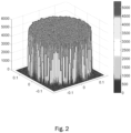
- case 1 corresponds to a single traffic area S T covering the full satellite coverage area S A with uniform traffic distribution (or Poisson Point Process, see Appendix A ).
- sub-cases c, d, e, f assume S T ⁇ S A .
- Fig. 2 shows the simulated traffic PDF for case 1.
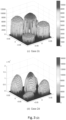
- Panels (a) to (f) of Fig. 3 show the uneven spot probability simulated traffic PDFs for sub-cases a to f of case 2, respectively.
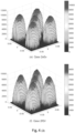
- Panels (a) to (f) of Fig. 4 show the even spot probability simulated traffic PDFs for sub-cases a to f of case 2, respectively.
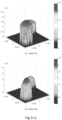
- Panels (a) to (f) of Fig. 5 show the uneven spot probability simulated traffic PDFs for sub-cases a to f of case 3, respectively.
- Table 6 Traffic geometry configurations for uneven spot traffic probabilities
- Case N TS r TS ( l ) ⁇ TS ( l ) S T / S A % p TS ( l ) ⁇ XX ⁇ YY ⁇ XY 1 1 sin( ⁇ max ) [0] 100 [1.0] NA NA NA 2a 5 1 ⁇ 2 3 0 , ⁇ ⁇ 4 , ⁇ 3 ⁇ 4 100 [0.3, 0.15, 0.1, 0.25, 0.2] 0.05 0.05 0.0 2b 5 1 ⁇ 2 3 0 , ⁇ ⁇ 4 , ⁇ 3 ⁇ 4 100 [0.3, 0.15, 0.1, 0.25, 0.2] 0.2 0.20 0.0 2c 5 0.22 0 , ⁇ ⁇ 4 , ⁇ 3 ⁇ 4 24.2 [0.3, 0.15, 0.1, 0.25, 0.2] 0.05 0.05 0.0 2d
- These techniques may also include techniques for virtual distancing of users (user terminals), and in particular techniques for selecting an appropriate set of beam centers or beam pointing directions (beam steering directions) given a set of users that request service.
- the aforementioned pragmatic M-MIMO approach describes a method for assigning users to different radio resources (e.g., time slots and/or frequency carriers) in a manner that maximizes the overall throughput.
- the power transfer matrix S has been introduced in reference literature 1 for the pragmatic M-MIMO approach. Its generic element s ( i,j ) describes the power transmitted for user j and received by user i.
- N U ( c ) represents the number of users allocated by the RRM to the color with number c.
- the matrix X is symmetric with unit diagonal elements and has the same dimensions as the power transfer matrix S. Matrices S and X can be combined by means of the Hadamard product, which will result in a co-channel power transfer matrix S CC that takes into account the radio resource assignments.
- SNR i s i i
- the resource management problem is cast into a color assignment problem that is formulated as a 0-1 integer programming instance on the coloring matrix binary entries.
- C the preassigned number of colors
- the interference matrix Q corresponds to the power transfer matrix S with all diagonal entries set to zero.
- the radio resource mapping assigns a plurality of users (user terminals) to a set of radio resource blocks (e.g., colors, color slices, or frames of a superframe, for example), for performing wireless communications between a hub station and the plurality of users.
- a set of radio resource blocks e.g., colors, color slices, or frames of a superframe, for example
- This method may be based, as input, on a set of quantities indicating mutual radio interferences between pairs of users among the plurality of users. Assuming a particular assignment of one or more users to a set of colors (as examples of radio resource blocks), this input can be used for determining indications of aggregated (co-channel) radio interferences that would be received by any non-assigned users if assigned to a respective color, from any users already assigned to the respective color.
- the matrix A defined below is one example of a set of indications of aggregated (co-channel) radio interferences. Its determination will be described next.
- the matrix Q is an example of a set of quantities indicating mutual radio interferences between pairs of users.
- the matrix C is an example of a radio resource mapping, in that it assigns users to colors (as examples of radio resource blocks).
- the richness of information offered by the matrix A can be exploited in a constructive way to assign color to users in a heuristic sequential way.
- the proposed method of determining the radio resource mapping may be an iterative method.
- the radio resource mapping e.g., coloring matrix
- the radio resource mapping may be determined in one or more iterations, by successively updating an intermediate radio resource mapping (e.g., intermediate or temporary coloring matrix) C ( n ) .
- the constraint may be applied that each user is assigned to at most one among the available colors.
- the first user selected and assigned to color 1 may be the one showing the highest interference from any other user.
- any radio resource mapping can be implemented by a mapping matrix
- any of the statements made above with regard to the coloring matrix C can be readily extended to generalized radio resource mappings.
- the radio resource mapping assigns a plurality of users (user terminals) to a set of radio resource blocks (e.g., colors (color slices), such as time slots, frequency slots, pseudo-random spreading sequences, polarization modes, frames of a superframe, or combinations thereof, for example), for performing wireless communications between a hub station and the plurality of users.
- each user terminal may be assigned to at least one (e.g., exactly one) radio resource block.
- the radio resource mapping is a color mapping.
- the color mapping may be implemented, for example, by a coloring matrix, such as coloring matrix C.
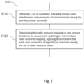
- Method 700 comprises steps S710 and S720 described below.
- a set of quantities indicating mutual radio interferences between pairs of user terminals among the plurality of (active) user terminals is obtained.
- An example of this set of quantities is given by the entries q ij of the interference matrix Q, or equivalently, the off-diagonal entries of the power transfer matrix S.
- obtaining the set of quantities indicating mutual radio interferences between pairs of (active) user terminals may comprise obtaining the N ⁇ N interference matrix Q (e.g., as defined above) that indicates mutual radio interferences between pairs of user terminals, where N is the number of (active) user terminals. It is understood that the relevant entries of the interference matrix Q may also be determined via determination of the power transfer matrix S. As explained above, an entry q ij of the interference matrix Q may indicate the power that is transmitted for the i -th user but received by the j -th user.
- obtaining the set of quantities indicating mutual radio interferences between pairs of user terminals may comprise obtaining a CN ⁇ CN generalized interference matrix Q ⁇ that indicates mutual radio interferences between pairs of user terminals among the plurality of user terminals.
- a first user terminal uses one of the of C radio resources
- a second user terminal uses another one of the of C radio resources.
- the set of quantities indicating mutual radio interferences between pairs of user terminals may be determined based on an independent determination of the antenna power beam pattern for each (active) user terminal.
- the set of quantities indicating mutual radio interferences between pairs of user terminals may be determined based on a channel matrix representing a complex transfer function between an antenna array of the hub-station array an the plurality of user terminals.
- the radio resource mapping (e.g., a color mapping implemented by coloring matrix C ) is determined in one or more iterations, by successively updating an intermediate radio resource mapping (e.g., an intermediate/temporary color mapping implemented by intermediate/temporary coloring matrix C ( n ) ), applying the constraint that each user terminal is assigned to at most one among the set of radio resource blocks (e.g., colors).
- an intermediate radio resource mapping e.g., an intermediate/temporary color mapping implemented by intermediate/temporary coloring matrix C ( n )
- Method 800 comprises steps S810 to S830.
- indications are determined of aggregated radio interferences that would be received by any non-assigned user terminals among the plurality of user terminals, if assigned to the respective radio resource block, from any user terminals already assigned to the respective radio resource block.
- determining the indications of aggregated radio interferences may comprise determining the N ⁇ C aggregated interference matrix A. This may be done, e.g., as per Eq. (27), by a matrix multiplication based on the interference matrix Q and the N ⁇ C (intermediate) radio resource mapping matrix C (or C ( n ) ), where C is the number of radio resource blocks.
- the matrix entries a ij of the aggregated interference matrix A may indicate an aggregated radio interference that an i -th user terminal would receive if assigned to a j -th radio resource block.
- the radio resource mapping matrix C may be a binary matrix that implements the intermediate radio resource mapping, with (binary) matrix entries c ij indicating whether or not the i -th user terminal is assigned to the j -th radio resource block.
- determining the indications of aggregated radio interferences may comprise determining an N ⁇ C aggregated interference matrix ⁇ by a reordering of a matrix multiplication based on the generalized interference matrix Q ⁇ and a vectorization of a N ⁇ C intermediate radio resource mapping matrix C (or C ( n ) ), where C is the number of radio resource blocks, with matrix entries a ij of the aggregated interference matrix ⁇ indicating an aggregated radio interference that an i -th user terminal would receive if assigned to a j -th radio resource block.
- the radio resource block is determined among the set of radio resource block that would result in the smallest aggregated radio interference for the given non-assigned user terminal. According to the above example, this would amount to selecting that color (as an example of a radio resource block) among the available colors that has associated therewith the smallest aggregated interference in the row of matrix A that corresponds to the given non-assigned user i ( n ) (e.g., the i ( n ) -th row of matrix A ).
- the intermediate radio resource mapping is updated to assign the given user terminal i ( n ) to the determined radio resource block.
- the intermediate/temporary coloring matrix C ( n ) may be updated so that the updated coloring matrix C ( n +1) assigns user terminal i ( n ) to color k ( n ) , in addition to any assignments of other users from previous iterations. This may amount to setting c ( i ( n ) , k ( n ) ) to from zero to one, e ( i ( n ) , k ( n ) ) ⁇ 1.
- the intermediate radio resource mapping may then be initialized to assign the selected user terminal i (1) to one among the set of radio resource blocks.
- said iterative determination may include one iteration for each of the remaining user terminals among the plurality of user terminals.
- each iteration after the first iteration may involve determining, based on the indications of aggregated radio interferences (e.g., based on the aggregated interference matrix A), a non-assigned user terminal that would receive the largest aggregated radio interference among the non-assigned user terminals for any of the radio resource blocks.
- This may amount to selecting, based on said indications, the non-assigned user terminal that has the largest aggregated radio interference.
- said indications specify a non-assigned user terminal and a potential assignment of this non-assigned user terminal to a radio resource block that would result in the largest aggregated radio interference among the aggregated radio interferences indicated by said indications.
- that radio resource block is considered that would result in the maximum aggregated radio interference for the respective user terminal, and subsequently, the user terminal is selected that has the largest maximum aggregated radio interference.
- This non-assigned user terminal is then selected.
- this may mean finding the largest entry in any of the rows of matrix A corresponding to non-assigned users (the remaining rows may be neglected for the determination, as noted above), and selecting the user terminal corresponding to the row in which this largest entry has been found.
- the determined non-assigned user terminal may then be selected as the given non-assigned user terminal for the current iteration.
- Which rows of matrix A need to be considered for the selection of the given user terminal may be governed by non-assigned user flags, user_flag( i ), as explained above.
- this user terminal may be selected as the given user terminal.
- newly active user terminals can be seamlessly added to an existing communication system.
- H-RRM in a generalized framework
- This matrix multiplication dominates the computational complexity of the algorithm with a multiplicative complexity of order ( N 2 C ).
- the binary coloring matrix C ( n +1) is the result of an update of the coloring matrix C ( n ) , which is the input of iteration ( n ) with the assignment of color k ( n ) to user i ( n ) during iteration ( n ) .
- a representation of the matrix Q as a re-ordered band-limited matrix or with an adjacency list would allow to further reduce the number of additions either to the number of non-null entries per column or to the vertical band of the matrix, respectively.
- Algorithm 2 An example of a fast version of Algorithm 1 which exploits the iterative update of the auxiliary co-channel interference matrix is shown in Algorithm 2. It is worth noting that for economy of operations, also the completion condition of the while loop is expressed with an iteratively updated counter in both algorithms.
- a location of an i -th user e.g., on the Earth surface
- a satellite or hub station in general
- angular coordinates such as azimuth and polar angles ⁇ i , ⁇ i
- cartesian coordinates such as u i , v i .
- u i sin ⁇ i cos ⁇ i
- v i sin ⁇ i sin ⁇ i
- ⁇ i u i 2 + v i 2
- ⁇ i tan ⁇ 1 v i u i .
- the parameter ⁇ can be adjusted to match the main beam of the antenna under assessment, which for example may be a square array of size D A (see, for example, reference literature 1).
- D A square array of size
- the Gaussian beam pattern approximation has a 4dB beamwidth corresponding to the array of size D A / ⁇ .
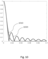
- An example of a comparison of the two patterns under the main-beam matching condition is shown in the graph of Fig. 10 , in which curve 1010 indicates g 0 and curve 1020 indicates g s .
- stochastic geometry is the discipline studying spatial patterns and has been extensively applied to modelling of terrestrial wireless networks performances.
- a spatial point pattern can be defined as a set of point locations within a Region of Interest (ROI). Each point, also indicated as event, is identified by its coordinates. For the present purpose, the user distribution in the u , v plane can be considered as a point pattern.
- Application of the H-RRM technique results in a number of slices, one per color (or resource block in general), and the geometrical properties of the slices can be analyzed to gain insight on performance trends.
- the benchmark model for spatial point patterns is the Poisson Point Process (PPP) (as described in Appendix A.I ) which exhibits Complete Spatial Randomness (CSR).
- PPP Poisson Point Process
- CSR Complete Spatial Randomness
- the points follow a Poisson Process over the study region which results in a uniform probability density function of intensity ⁇ , where ⁇ is the mean number of points per unit area.
- PDP Poisson Disk Process
- the nearest-neighbor distance distribution function ⁇ ( r ) known as Diggle's G-function, describes the cumulative distribution of the distance of a random point to the nearest point (event-to-event) in the point pattern.
- ⁇ ( r ) A comparison of the empirical distribution function of the point pattern under analysis to the theoretical distribution of the PPP with the same density of points (details of the normalization rescaling are described in Appendix A ) offers a summary of effects that the RRM induces on the distancing of the points of a same slice.
- N / C 250, 500, and 1000
- different number of slices e.g., colors, or radio resource blocks in general.
- the re-scaling of the empirical distributions to a normalized density evidences that the effects of the H-RRM are substantially independent of the size of the population and mainly depend on the number of slices (e.g., colors).
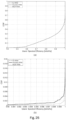
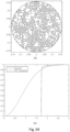
- Fig. 15 The asymptotic effects of the number of slices (e.g., colors, or radio resource blocks in general) on the distributions of nearest-neighbor distances can be seen from Fig. 15 , in which a saturation effect can be observed.
- This figure also shows a best fitting of the empirical distributions to the cumulative distributions of Weibull three-parameters PDFs. The best fitting parameters have been obtained by Maximum-Likelihood Estimation.
- the virtual distancing techniques described in the following sub-sections are based on the observation that once the colors are assigned, the beam positions determine the useful gains and unwanted interference for all users in the resource slot (e.g., color) under consideration.
- An optimization of the beam positions that guarantees a useful gain for the wanted user while reducing the interference to the users in the same slot may obtain an improvement in the overall throughput.
- the beam positions optimization can be seen as a distancing of the beams from the nearest-neighbor users. In this manner the distance between the users is "virtually" increased.
- each row element of the column vector Q 1 can be interpreted as a downlink interference per user; all the users of color k contribute to the interference experienced by user i.
- Each column element of the row vector 1 T Q can be interpreted as the aggregated interference generated by user j on all the other users. Similarly to the uplink case, the user j is interfered by all the users sharing the same color.
- beam s j serves user u j .
- the optimization search space must be constrained to a maximum gain loss ⁇ G max g A 0 2 ⁇ g A u j ⁇ s j 2 ⁇ ⁇ G max .
- the constraint on the maximum gain loss can be translated into a constraint on the maximum displacement radius of the beam pointing direction s j s j ⁇ u j ⁇ r max .
- optimization of the i-th beam position (beam pointing direction, or beam steering direction) s i can be translated into the analog problem of optimally distancing beam s i from the position of the co-channel users u j while limiting the gain loss for the served user u i .
- user position and user user terminal
- beam pointing direction and beam may be used synonymously.
- Method 1600 is a method of determining beam pointing directions (beam positions) for performing wireless communications between a hub station and a plurality of user terminals (users). It comprises step S1610 that is performed for at least one of the user terminals (or beams) and that is a step of iteratively determining a beam pointing direction for serving the at least one user terminal u i by incrementally updating an intermediate beam pointing direction (temporary/current beam pointing direction) s i n until a termination criterion is met.
- the intermediate pointing direction s i n is incrementally updated such that the value of a cost function is optimized (e.g., minimized) under the constraint that a gain towards the at least one user terminal u i for the intermediate pointing direction s i n exceeds (or at least, is not less than) a predefined minimum gain (e.g., minimum gain
- the cost function is designed to penalize aggregated interference that a beam pointing in the intermediate beam pointing direction s i n would cause for the remaining user terminals u j , j ⁇ i, among the plurality of user terminals. Thereby, optimization of the value of the cost function will optimize (e.g., reduce or minimize) the aggregated interference.
- the constraint that the gain towards the at least one user terminal u i for the current beam pointing direction s i n exceeds the predefined minimum gain may translate into a constraint that the intermediate beam pointing direction s i n differs from a direction pointing towards the user terminal u i to be served by less than a predefined amount (e.g., r max ). Enforcing this constraint may trigger the aforementioned termination criterion, i.e., an iteration in which the constraint needs to be enforced may be the terminal iteration for the (served) user terminal at hand. Further, the repeated incremental updating of the intermediate beam pointing direction s i n may eventually valorize gain toward the (served) at least one user terminal u i for the respective intermediate beam pointing direction s i n .
- a predefined amount e.g., r max
- the virtual distancing technique may exploit analogies with molecular dynamics.
- beam and user positions may be considered as a system of particles. While beams are free to move, users remain fixed.
- each of the aforementioned iterations at step S1610 may involve incrementally updating the intermediate beam pointing direction (current/temporary beam pointing direction) s i n such that the value of the cost function is optimized (e.g., minimized) under the constraint that a difference between the intermediate beam pointing direction s i n and a direction pointing towards the at least one user terminal u i does not exceed a predefined maximum difference.
- the cost function may be designed to penalize closeness between the intermediate beam pointing direction s i n and respective directions pointing towards the remaining user terminals u j , j ⁇ i, among the plurality of user terminals if differences between the intermediate beam pointing direction s i n and the respective directions pointing towards the remaining user terminals u j , j ⁇ i, are less than a predefined threshold. Further, for any of the remaining user terminals u j , j ⁇ i, the respective penalty may increase as the difference between the intermediate beam pointing direction s i n and the direction pointing towards the respective one among the remaining user terminals u j , j ⁇ i, decreases.
- the beam center s i (e.g., the intermediate beam pointing direction) moves according to repulsive forces between the beam center s i and the co-channel user positions u j , j ⁇ i (as shown in panel (b) of Fig. 17 ).
- the force on s i due to the interaction with u j is denoted by F i,j .
- Method 1800 comprises steps S1810 and S1820.
- optimization of the value of the cost function in each iteration at step S1610 may involve step S1810 of determining a set of (virtual) forces between the directions pointing towards the remaining user terminals u j , j ⁇ i, and the intermediate beam pointing direction s i n .
- These (virtual) forces may be repulsive forces that act on the intermediate beam pointing direction s i n and that depend on respective differences between the intermediate beam pointing direction s i n and respective directions pointing towards the remaining user terminals u j , j ⁇ i.
- the force magnitude of the (virtual) forces may be modelled, for example, accordingly to a (modified) Hooke's elastic law.
- the (virtual) forces may have one or more of the following properties:
- the elastic force of Eq. (52) is truncated to the repulsive side (i.e., F i,j ⁇ 0 for r i,j ⁇ d min ) so that a beam at a distance greater than d min from a user is not subject to any force.
- optimization of the value of the cost function in each iteration at step S1610 thus may further involve step S1820 of determining an update amount for the intermediate beam pointing direction s i n based on a (virtual) net force (e.g., net force F i ) of the set of virtual forces (e.g., forces F i,j ).
- the update amount may indicate an update direction and an update magnitude.
- Said update amount may be determined by numeric integration, for example.
- the aforementioned constraint on minimum gain and/or maximum distance may be implemented by a hard cut-off for the update amount of the current beam pointing direction s i n , for example. As noted above, enforcing the hard cut-off may trigger the termination criterion.
- An example of a possible derivation of the update amount is presented next.
- the constant ⁇ covers the effects due to (virtual) particle mass and time interval (e.g., assumed time interval between one iteration and another in the moving particles analogy).
- the constant ⁇ can be used as a "dumping constant" that can be tuned and/or made adaptive to control the convergence of the optimization.
- ⁇ may be a positive constant (with appropriate units).
- the algorithm may terminate for example when the position difference ⁇ s i n is below a defined tolerance.
- the termination criterion for the algorithm may relate to one or more of:
- Panel (c) of Fig. 17 shows how the VDI algorithm converges to beam positions that fulfill the distancing condition starting from the user positions of panel (a).
- An example of the final beam layout with representative beam-widths is depicted in panel (d) of Fig. 17 .
- Reference literature 1 describes a regular sampling of the zone of interest based on a lattice of beam positions.
- This technique termed Switchable Fixed Multi-Beam architecture (MB in short)
- MB Switchable Fixed Multi-Beam architecture
- a bi-dimensional lattice of beam positions is defined by means of two basis vectors ( s a and s b ).
- the beam-to-user assignment can be performed according to different criteria. If maximum gain is the selected criterion, the bi-dimensional quantizer is defined by the Voronoi partition of the space into non overlapping cells.
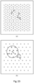
- An example of such beam-to-user assignment (i.e., maximum gain assignment) is schematically illustrated in panel (a) of Fig. 23 .
- the selected optimal beam position s i on the discrete beam lattice ⁇ ( S ) should minimize the interference to co-channel users u j , j ⁇ i, while guaranteeing a limited gain loss impact for the served user u i .
- An example of such minimum interference assignment is schematically illustrated in panel (b) of Fig. 23 .
- Method 2200 comprises steps S2210 to S2230 that may be performed for at least one user terminal u i to be served. For example, these steps may be performed for each of the plurality of user terminals.
- the plurality of user terminals may relate to user terminals that are jointly served within a given radio resource block (e.g., color slice), i.e., they may correspond to co-channel users. Further, the user terminals may be located at (substantially) known locations.
- a set of candidate beam pointing directions among a predefined set of beam pointing directions is determined. This is done in such matter that the candidate beam pointing directions differ from a direction pointing towards the at least one user terminal u i by less than a predefined amount (e.g., by less than r max introduced below).
- the predefined set of beam pointing directions may correspond to a plurality of fixed beams, where each beam has a respective beam pointing direction and a respective beam center.
- the beam centers of the plurality of fixed beams may be arranged at the vertices of a regular lattice (e.g., lattice ⁇ ( S ), or lattice ⁇ ( S MB ) described below).
- a quantity is determined that is positively correlated with (e.g., proportional to) an aggregated interference that a beam pointing in the respective candidate beam pointing direction would cause for the remaining user terminals u j , j ⁇ i among the plurality of user terminals, or that is positively correlated with (e.g., proportional to) an aggregated interference that a beam pointing in the respective candidate beam pointing direction would receive from the remaining user terminals u j , j ⁇ i among the plurality of user terminals.
- the two above-mentioned alternatives for the determined quantity may relate to the hub station acting either as a transmit hub station or a receive hub station, respectively.
- the determined quantity for the given candidate beam pointing direction may be further inversely proportional to a gain, towards the at least one user terminal, of the beam pointing in the given candidate beam pointing direction.
- the determined quantity may be the quantity defined in Eq. (58).
- the candidate beam pointing direction among the set of candidate beam pointing directions that minimizes said quantity is selected for serving the at least one user terminal u i .
- ⁇ r max drastically limits the search space in ⁇ ( S ) to the lattice points within the circle of radius r max and center u i .
- An example of this criterion is schematically illustrated in panel (b) of Fig. 23 , in which the thick-lines circles inside the circle centered on u i indicate candidate lattice points (candidate beam pointing directions). For such limited number of candidates, the evaluation of the array factor for all the co-channel user locations is of affordable computational complexity.
- the candidate beams can be found in the subset of ⁇ s k ⁇ as those beams that (additionally) fulfill the maximum distance constraint ⁇
- the sum-interference can be evaluated and the minimum of the resulting sum-interferences can be found.
- QVD Quantized Virtual Distancing
- the plurality of fixed beams may have a normalized beam spacing S MB n between adjacent beams that is smaller than 1, for example.
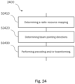
- Fig. 24 shows an example of a method 2400 of performing wireless communications between a hub station and a plurality of user terminals.
- Method 2400 may comprise any one, any two, or all three of steps S2410, S2420, and S2430.
- step S2410 is a step of determining a radio resource mapping according to the techniques described above (e.g., according to methods 700 and/or 800).
- Step S2420 is a step of determining beam pointing directions according to the techniques described above (e.g., according to methods 1600 and/or 1800, or method 2200).
- Step S2430 is a step of precoding and/or beamforming.
- the M-MIMO satellite multibeam simulator described in reference literature 1 has been evolved to include the required additional functionalities. More specifically. the following features have been introduced:
- the present disclosure does not assume a fixed number of users allocated to each slice N U anymore, as this parameter fluctuates depending on the specific non uniform traffic realization and consequent RRM users allocation per frame.
- the average number of users per frame will be indicated by N U .
- VDI results will not be reported here as the respective performance was found to be similar or worse than that of QVD, which is simpler to implement in a practical satellite payload.
- GSO Geostationary Satellite
- Table 3 Simulation system parameters Parameter Symbol Value Unit Number of Monte Carlo Trials N trials 5-10 Carrier frequency f 0 20.0 GHz User baud rate R s 500.00 Msymb/s Total payload RF power per carrier P T c 1.0-2.0 kW Minimum ACM physical layer SNIR SNIR min -10.00 dB User minimum spacing coefficient 1.0 Minimum satellite elevation angle ⁇ min 5.00 degrees Array size D A 1.2-2.0 m Array element aperture efficiency ⁇ E -1 dB Array elements normalized spacing d A / ⁇ 1.4-2.6 MB normalized beam spacing S MB n 0.2 Number of array elements N T 1156-3136 Number of feeds/users ratio N T / N U 2-28 Aver. no.
- the number of frames within the superframe allows to reorganize the users served at a given time to approximate the MIQP distance distribution.
- the MIQP algorithm represents a lower bound to the optimum PDP minimum distance users' distribution used in reference literature 1.
- N FR the greater the number of frames N FR , the easier the H-RRM algorithm task will be.
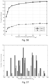
- Fig. 26 shows the simulated Shannon MB throughput as a function of the number of frames for traffic cases 2f and 3f of Table 1 and 1.2m DRA size. In the simulations the optimized N T / N U value given in Table 4 has been used.
- N FR 30 has been adopted for the following simulations. This provides almost asymptotic throughput performance with an acceptable superframe duration. For this number of frames, the throughput variation across the different frames for traffic case 2f was assessed to be less than 1%.
- the proposed H-RRM algorithms divide the users to be served among the different frames (or correspondingly, slices) composing the superframe, selecting for each frame a subset of users which can be mapped to beams maintaining a certain level of interference isolation from/to the other active beams.
- the number of active beams per frame allocated by the H-RRM algorithms is a random variable with an optimum average value N U , which depends on the traffic distribution parameters.
- N U The most important parameters affecting the N U value are the number of antenna array elements N T and the traffic over overall potential satellite coverage area S T / S A ratio.
- N T / N U ratio As will be shown in Section IV.C.5, it has been found experimentally that once the N T / N U ratio has been derived for configuration 'a', its value can be extrapolated to another traffic case 'x' by simply scaling it up with the ratio of traffic areas ratio S T x / S T a .
- Table 4 and Table 5 summarize the Shannon throughput simulation results for the various traffic configurations described in Section II.C. For each traffic configuration, several simulations have been run to find the value of N T / N U that optimizes the throughput. It can be noted that the predicted value for [ N T / N U ] opt following the approach described in Section IV.C.4 provides satisfactory results at least for the cases reported in Table 4.
- QVD throughput is generally better than MB, but also better that MF in several cases.
- the exceptions are represented by cases 2a, 2b (MF and MB), and 3a (MF only).
- use of the QVD RRM algorithm is recommended with a performance advantage as high as 9%.
- the best performance can be obtained for the case of even spots traffic probability reported in Table 5.
- the throughput difference between uneven and even spot traffic probabilities is limited to about 10%, which is considered negligible.
- This finding demonstrates the H-RRM robustness to the variation of traffic distribution. This is also confirmed by the limited difference in throughput between cases 2a vs 2b and 3a vs 3b.
- the almost proportional dependency of throughput on the S T / S A ratio is apparent, although the slope is more pronounced for case 3 than for case 2. It is evident that there is limited throughput difference between the cases of even and uneven spot traffic probabilities, which are quite different in terms of traffic density (see Fig. 3 and Fig. 5 for uneven spot probabilities, and Fig. 4 and Fig. 6 for even spot probabilities).
- Table 6 and Table 7 summarize the DVB-S2X throughput simulation results for the various traffic configurations described in Section II.C above. As expected, the throughput is lower than for the Shannon case, but the results are in line with the previous findings.
- the HRRM + QVD vs S-RRM + MMSE gain is up to 42% and 38% for cases 1 and 3d instead of a respective loss of -8% and -10% when comparing H-RRM + QVD to H-RRM + MMSE.
- Table 8 Shannon throughput results impact for: a) H-RRM and QVD (H-RRM+QVD) vs simple RRM and MMSE (S-RRM+MMSE); b) H-RRM and QVD (H-RRM+QVD) vs H-RRM and MMSE (H-RRM+MMSE) Case Sub-case Shannon Throughput ⁇ % H-RRM+QVD vs S-RRM+MMSE H-RRM+QVD vs H-RRM+MMSE 1 NA +41.7 -8.1 2 a +16.0 -7.5 d +35.0 -11.0 f +29.1 -11.0 3 a +28.3 -8.9 d +37.8 -10.3 f +31.8 -10.8
- Table 9 DVB-S2X throughput results impact for: a) H-RRM and QVD (H-RRM+QVD) vs simple RRM and MMSE (S-RRM+MMSE
- the 2m array size is more demanding in terms of simulation time.
- the present section focuses on the uneven traffic spots probability case, reusing the optimized N T / N U values previously derived.
- Table 12 and Table 13 respectively summarize the Shannon and DVB-S2X throughput simulation results for a DRA of 2.0m size and the various traffic configurations described in Section II.C.
- Concerning the throughput performance for the various M-MIMO schemes with RRM it is noted that for case 1 (full visible Earth uniform traffic distribution or PPP distribution) the H-RRM QVD throughput is by 13.5% lower than for case 0.
- case 1 full visible Earth uniform traffic distribution or PPP distribution
- the H-RRM QVD throughput is by 13.5% lower than for case 0.
- the above comments related to 1.2m DRA size as regards the dependence on the traffic cases are also applicable here.
- the main difference is that for the 2.0m array size the QVD loss versus MMSE can be as high as 25%, i.e., almost twice the loss compared to the 1.2m DRA size case.
- this pragmatic M-MIMO QVD performance loss will be turned into a QVD gain when practical MMSE implementation aspects will be considered.
- the MB + QVD complexity is much lower compared to the MMSE solution.
- the proposed H-RRM for M-MIMO has been shown to closely approximate the NP-Hard MIQP performance and to be robust with respect to very different traffic distributions.
- the linear complexity H-RRM throughput when applied to the pragmatic MB M-MIMO is 12% to 24% lower than for the much more complex MMSE precoding technique with H-RRM and assuming perfect channel knowledge for the 1.2m and 2.0m DRA cases, respectively.
- the MB M-MIMO H-RRM show 23% to 53% throughput advantage compared thereto.
- the H-RRM is shown to be very robust to the users' spatial distributions, and the key RRM parameters are easy to adapt to current traffic conditions.
- the H-RRM and beam assignment algorithms proposed in the present disclosure are well matched to the MB M-MIMO beam-hopped fixed grid of beams architecture that does not require any adaptive beam forming (fixed beam grid generation, as described for example in reference literature 1). Furthermore, the proposed RRM can be implemented on ground and the hopping pattern can be uploaded to the satellite via conventional telecommand functionality.
- the H-RRM MB M-MIMO physical layer can be based on the current DVB-S2X standard, thus making it a short-term close to optimum feasible solution.
- the present disclosure likewise relates to apparatus for performing methods and techniques described throughout the disclosure.
- the apparatus may comprise one or more processors and a memory coupled to the processor(s).
- the processor may be adapted to carry out all steps of the methods described throughout the disclosure.
- This apparatus may relate to a controller of a hub station, for example.
- the present disclosure likewise relates to a computer program comprising instructions that, when executed by a processor (e.g., computer processor, server processor), cause the processor to carry out all steps of the methods described throughout the disclosure.
- a processor e.g., computer processor, server processor
- the present disclosure likewise relates to a computer-readable storage medium storing the aforementioned computer program.
- circuitry, units, or blocks described throughout the present disclosure may be implemented by a computer processor or respective computer processors, or the like.
- EEE1 A method of determining beam pointing directions for performing wireless communications between a hub station and a plurality of user terminals, the method comprising, for at least one of the user terminals:
- EEE2 The method according to EEE1, wherein the determined quantity for a given candidate beam pointing direction is further inversely proportional to a gain, towards the at least one user terminal, of the beam pointing in the given candidate beam pointing direction.
- EEE3 The method according to EEE1 or EEE2, wherein the predefined set of beam pointing directions corresponds to a plurality of fixed beams, each beam having a respective beam pointing direction and a respective beam center; and wherein the beam centers of the plurality of fixed beams are arranged at the vertices of a regular lattice.
- EEE4 The method according to EEE3, wherein the plurality of fixed beams have a normalized beam spacing between adjacent beams that is smaller than 1.
- EEE5. A method of determining beam pointing directions for performing wireless communications between a hub station and a plurality of user terminals, the method comprising, for at least one of the user terminals:
- EEE6 The method according to EEE5, wherein for each iteration, the intermediate beam pointing direction is incrementally updated such that the value of the cost function is optimized under the constraint that a difference between the intermediate beam pointing direction and a direction pointing towards the at least one user terminal does not exceed a predefined maximum difference, wherein the cost function is designed to penalize closeness between the intermediate beam pointing direction and respective directions pointing towards the remaining user terminals among the plurality of user terminals if differences between the intermediate beam pointing direction and the respective directions pointing towards the remaining user terminals are less than a predefined threshold, and wherein, for any of the remaining user terminals, the respective penalty increases as the difference between the intermediate beam pointing direction and the direction pointing towards the respective one among the remaining user terminals decreases.
- EEE7 The method according to EEE6, wherein optimization of the value of the cost function in each iteration involves:
- EEE8 The method according to EEE7, wherein the virtual forces are modeled to be zero if the respective differences between the intermediate beam pointing direction and respective directions pointing towards the remaining user terminals exceed the predefined threshold.
- EEE9 The method according to EEE6 or EEE7, wherein the virtual forces are modeled to be discontinuous at the predefined threshold for respective differences between the intermediate beam pointing direction and respective directions pointing towards the remaining user terminals.
- EEE10 The method according to any one of EEE5 to EEE9, wherein the termination criterion relates to at least one of:
- a method of determining a radio resource mapping that assigns a plurality of user terminals to a set of radio resource blocks, for performing wireless communications between a hub station and the plurality of user terminals comprising:
- EEE12 The method according to EEE11, further comprising, in each iteration:
- EEE13 The method according to EEE11, wherein the given non-assigned user terminal is a user terminal that newly requests wireless communication with the hub station.
- EEE14 The method according to any one of EEE11 to EEE13, further comprising, in a first iteration:
- EEE15 The method according to any one of EEE11 to EEE14, wherein obtaining the set of quantities indicating mutual radio interferences between pairs of user terminals among the plurality of user terminals comprises obtaining an N ⁇ N interference matrix Q that indicates mutual radio interferences between pairs of user terminals among the plurality of user terminals, where N is the number of user terminals;
- EEE16 The method according to any one of EEE11 to EEE15, further comprising: determining the set of quantities indicating mutual radio interferences between pairs of user terminals among the plurality of user terminals based on mutual distances on ground between the user terminals among the plurality of terminals.
- EEE17 The method according to any one of EEE11 to EEE15, further comprising: determining the set of quantities indicating mutual radio interferences between pairs of user terminals among the plurality of user terminals based on an independent determination of a beam pattern for each user terminal among the plurality of user terminals.
- EEE18 The method according to any one of EEE11 to EEE15, further comprising: determining the set of quantities indicating mutual radio interferences between pairs of user terminals among the plurality of user terminals based on a channel matrix representing a complex transfer function between an antenna array of the hub-station array an the plurality of user terminals.
- EEE19 The method according to any one of EEE11 to EEE15, wherein obtaining the set of quantities indicating mutual radio interferences between pairs of user terminals among the plurality of user terminals comprises obtaining a CN ⁇ CN generalized interference matrix Q ⁇ that indicates mutual radio interferences between pairs of user terminals among the plurality of user terminals, with a first user terminal using one of the of C radio resources, and a second user terminal using another one of the of C radio resources, where N is the number of user terminals;
- EEE20 The method according to any one of EEE11 to EEE19, wherein the radio resource blocks are time slots, frequency slots, pseudo-random spreading sequences, polarization modes, or combinations thereof.
- a method of performing wireless communications between a hub station and a plurality of user terminals comprising:
- EEE22 The method according to EEE21, further comprising precoding and/or beamforming.
- EEE23 An apparatus comprising a computer processor, wherein the computer processor is adapted to perform the steps of the method according to any one of EEE1 to EEE22.
- EEE24 A computer program including instructions that when executed by a computer processor would cause the computer processor to perform the steps of the method according to any one of EEE1 to EEE22.
- EEE25 A computer-readable storage medium storing the computer program according to EEE24.
- the Poisson Disk Process also known as Poisson Hard-Core Process (PHCP) is a point process with a uniform distribution of occurrence of points in the region of interest with the additional constraint that each point of the pattern must be separated from the other points by a minimum distance 2 r min , where the parameter r min is called the Poisson disk radius. It is worth noting that reference literature 1 has empirically shown that a user distribution according to PDP characteristics provides optimal throughput performance.
- the algorithms, techniques, and methods described throughout the present disclosure manipulate an input point pattern in a single (as in the case of VDI and QVD) or in multiple (as in the case of RRM) output point patterns.
- the input point pattern represents the geometrical distribution of users, which can be simulated as the realization of a set of random variables based on a continuous bi-dimensional probability density function.
- the performance of the algorithms can be assessed with an analysis of the nearest-neighbor distance statistics of the output point patterns. For this reason, some of the techniques for point pattern analysis need to be discussed/adapted.
- the nearest-neighbor distance can be evaluated to build the empirical distribution function, viz., a staircase function with steps of height 1/N (where N is the number of points) for each of the ordered nearest-neighbor distances.
- a re-scaling of the distance to the PPP mean nearest-neighbor distance can be introduced for the given point density.
- the re-scaling procedure may be performed as follows:
- Fig. 33 illustrates the Poisson Point Pattern and panel (b) illustrates the corresponding Diggle's G-function (800 points).
- Panel (a) of Fig. 34 illustrates the point pattern of the Poisson Disk Process and panel (b) illustrates the corresponding Diggle's G-function (800 points).
- panel (a) of Fig. 35 illustrates a realization of the RRM point pattern and panel (b) illustrates the corresponding Diggle's G-function (800 points).
- MLE Maximum likelihood estimation
- PDF probability density function
- the hub-station is assumed to transmit to the j-th user by means of the l -th radio resource (e.g., time slots in Time Division Multiplexing (TDM), carriers' frequency in frequency in Frequency Division Multiplexing (FDM), polarizations, direct-sequence spread-spectrum code in case of Code Division Multiplexing (CDM) or any combination of these including polarization reuse which allows to double the TDM/FDM/CDM colors).
- TDM Time Division Multiplexing
- FDM Frequency Division Multiplexing
- CDM Code Division Multiplexing
- color is used as a synonym for radio resource block or radio resource of any kind.
- the system throughput can be evaluated as the sum of the individual users' throughput contributions T S ( i ) .
- R s the carrier baud rate
- ⁇ is the duty cycle.
- Eq. (81) is in accordance with the notation adopted in Section II.B, Eq.
- the sum-capacity T T S is evaluated for the given user distribution.
- this formulation hides the fact that when the hub station is composed by an array of antennas (e.g., with fixed or reconfigurable beamforming and/or precoding), the generalized power transfer coefficients s ( i, k
- the color assignment and the beamforming/precoding optimization are coupled problems, as the optimal precoding/beamforming depends strongly on the active users sharing the same color. Additionally, for a certain assignment of users to colors, the optimal precoding/beamforming will be color dependent (e.g., due to frequency dispersion of the channel row vectors).
- each precoding/beamforming vector depends only on the geometry and link conditions of each associated user (they are determined, for user j, at color l by the channel row vector h j l l ).
- w(h) will indicate the mapping function that determines a zero-order approximation of the optimal precoding/beamforming vector given the channel row vector h.
- the precoding/beamforming optimization and normalization can be performed according to either known techniques (e.g., Matched-Filter, Zero-Forcing, Minimum-Mean-Square-Error, Pragmatic Multi-Beam, etc.) or newly disclosed techniques (e.g., Virtual Distancing or Quantized Virtual Distancing).
- known techniques e.g., Matched-Filter, Zero-Forcing, Minimum-Mean-Square-Error, Pragmatic Multi-Beam, etc.
- newly disclosed techniques e.g., Virtual Distancing or Quantized Virtual Distancing.
- a generalized interference matrix Q ⁇ can be obtained.
- the matrix Q ⁇ can be obtained from the coefficients q( i, k
- MIQP Mixed Integer Quadratic Programming
- a or vec (A) The information contained in A or vec (A) is the same, but for homogeneity of description of the heuristic algorithm the inverse vectorization operation, vec -1 ( ), is introduced, which is a re-shaping operation that transforms a vector into a matrix.
- the temporary auxiliary matrix A ( n ) can be evaluated, and one can select, among the non-assigned users, the one (row) with worst interference and for it the least interfering color (within the row).
- the above generalization for the evaluation of the temporary auxiliary matrix A ( n ) are the only modifications that need to be applied to the heuristic coloring algorithm.
- color l ( n ) is assigned to user j ( n ) .
- the notation Q j C indicates the j-th column of the matrix Q.
- Eq. (122) above can be interpreted as the fact that the assignment of color l ( n ) to user j ( n ) increases each color column vector interference of A ( n ) with relevant contribution.
- This equation provides also a fast update of the auxiliary matrix A ( n ) which avoids any matrix multiplication with substantial computational speed-up.
- further simplifications can be performed, as described below.
- the generalized interference matrix Q ⁇ is broadly non-null and composed of block sub-matrices Q k l .
- Radio Resource Management in M-MIMO based on the disclosed Heuristic Radio Resource Management algorithm(s) will be described.
- the formulation will be first detailed for the Color-independent/Orthogonal colors case, i.e., the channel matrix H is independent (or approximately independent) of the radio resource (e.g., single-carrier TDM or narrowband FDM and/or MF-TDM), and the assignment of a given radio resource to a user does not generate interference to users assigned to different colors.
- the radio resource e.g., single-carrier TDM or narrowband FDM and/or MF-TDM
- precoding/beamforming matrix W could be derived according to any of the known M-MIMO techniques, such as
- the power transfer matrix S can now be used as input to the Heuristic RRM. Once the sets of users per color are known, the optimal precoding/beamforming matrices for each set can be evaluated. It is to be remarked that for terrestrial wireless networks, the channel matrix H estimation is eased by the fact that the channel reciprocity in case of commonly used Time Division Duplexing (TDD) can be used. Techniques for M-MIMO channel matrix estimation in wireless terrestrial networks are summarized in Chapter 3 of the book "Massive MIMO Networks: Spectral, Energy, and Hardware Efficiency", by Emil Björnson, Jakob Hoydis, Luca Sanguinetti, http://www.nowpublishers.com (reference literature 4).
- the matrices ( H H H ) + or ( HH H ) + of zero forcing as well as the matrices ( H H H + ⁇ I ) -1 or H H ( H H H + ⁇ I ) -1 of the MMSE are corrective terms to the zero-order matrix H H of the matched filter precoding/beamforming matrix.
- the information of the channel response for each user j, for receiving color k when the hub-station array transmits at color l, h j k l would be needed.
- This information is collected in block channel matrices H k
- the form of the power transfer matrices is summarized below.
Landscapes
- Engineering & Computer Science (AREA)
- Computer Networks & Wireless Communication (AREA)
- Signal Processing (AREA)
- Physics & Mathematics (AREA)
- Astronomy & Astrophysics (AREA)
- Aviation & Aerospace Engineering (AREA)
- General Physics & Mathematics (AREA)
- Mobile Radio Communication Systems (AREA)
- Radio Relay Systems (AREA)
Priority Applications (1)
| Application Number | Priority Date | Filing Date | Title |
|---|---|---|---|
| EP25169422.0A EP4561140A3 (fr) | 2021-08-20 | 2021-08-20 | Gestion heuristique de ressources radio pour mimo massif dans des réseaux de communication satellite large bande |
Applications Claiming Priority (3)
| Application Number | Priority Date | Filing Date | Title |
|---|---|---|---|
| PCT/EP2021/073148 WO2023020702A1 (fr) | 2021-08-20 | 2021-08-20 | Gestion de ressources radio heuristiques pour mimo massif dans des réseaux de communication à large bande par satellite |
| EP21763351.0A EP4388674A1 (fr) | 2021-08-20 | 2021-08-20 | Gestion de ressources radio heuristiques pour mimo massif dans des réseaux de communication à large bande par satellite |
| EP25169422.0A EP4561140A3 (fr) | 2021-08-20 | 2021-08-20 | Gestion heuristique de ressources radio pour mimo massif dans des réseaux de communication satellite large bande |
Related Parent Applications (1)
| Application Number | Title | Priority Date | Filing Date |
|---|---|---|---|
| EP21763351.0A Division EP4388674A1 (fr) | 2021-08-20 | 2021-08-20 | Gestion de ressources radio heuristiques pour mimo massif dans des réseaux de communication à large bande par satellite |
Publications (2)
| Publication Number | Publication Date |
|---|---|
| EP4561140A2 true EP4561140A2 (fr) | 2025-05-28 |
| EP4561140A3 EP4561140A3 (fr) | 2025-11-19 |
Family
ID=77595558
Family Applications (2)
| Application Number | Title | Priority Date | Filing Date |
|---|---|---|---|
| EP25169422.0A Pending EP4561140A3 (fr) | 2021-08-20 | 2021-08-20 | Gestion heuristique de ressources radio pour mimo massif dans des réseaux de communication satellite large bande |
| EP21763351.0A Pending EP4388674A1 (fr) | 2021-08-20 | 2021-08-20 | Gestion de ressources radio heuristiques pour mimo massif dans des réseaux de communication à large bande par satellite |
Family Applications After (1)
| Application Number | Title | Priority Date | Filing Date |
|---|---|---|---|
| EP21763351.0A Pending EP4388674A1 (fr) | 2021-08-20 | 2021-08-20 | Gestion de ressources radio heuristiques pour mimo massif dans des réseaux de communication à large bande par satellite |
Country Status (5)
| Country | Link |
|---|---|
| US (1) | US20250047363A1 (fr) |
| EP (2) | EP4561140A3 (fr) |
| CA (1) | CA3228525A1 (fr) |
| IL (1) | IL310944A (fr) |
| WO (1) | WO2023020702A1 (fr) |
Families Citing this family (3)
| Publication number | Priority date | Publication date | Assignee | Title |
|---|---|---|---|---|
| CN116955924B (zh) * | 2023-06-14 | 2025-10-31 | 中国人民解放军网络空间部队信息工程大学 | 一种复杂海洋环境下的多目标辐射噪声特征提取方法及装置 |
| CN120224228B (zh) * | 2025-05-26 | 2025-08-19 | 北京华迅通信技术有限公司 | 一种基于环境自适应的5g通信方法及系统 |
| CN121208530B (zh) * | 2025-11-28 | 2026-02-13 | 华东交通大学 | 一种基于混合整数凸二次规划的电网行波同步定位方法 |
Citations (2)
| Publication number | Priority date | Publication date | Assignee | Title |
|---|---|---|---|---|
| FR120M (fr) | 1959-08-12 | 1961-01-09 | Madaus & Co Dr | Nouvelle composition laxative. |
| EP2296225A1 (fr) | 2009-09-10 | 2011-03-16 | Agence Spatiale Européenne | Architecture reconfigurable de réseau de formation de faisceaux |
Family Cites Families (18)
| Publication number | Priority date | Publication date | Assignee | Title |
|---|---|---|---|---|
| FR120E (fr) | ||||
| BRPI0715009A2 (pt) * | 2006-09-14 | 2014-09-16 | Interdigital Technology Corporation | Método de comunicação sem fio e aparato para atribuir células e blocos de recursos. |
| US8478342B2 (en) * | 2009-11-19 | 2013-07-02 | Texas Instruments Incorporated | Inter-cell interference coordination |
| EP2689610B1 (fr) * | 2011-03-24 | 2020-07-01 | BlackBerry Limited | Sélection de ressources radio habilitées pour un dispositif |
| EP2632061B1 (fr) * | 2012-02-27 | 2020-09-02 | Agence Spatiale Européenne | Procédé et système permettant de fournir une couverture multifaisceau d'une région d'intérêt dans des communications par satellite à faisceaux multiples |
| US10085154B2 (en) * | 2012-10-17 | 2018-09-25 | Huawei Technologies Co., Ltd. | System and method for dynamic inter-cell interference coordination |
| SG11201510716QA (en) * | 2013-07-02 | 2016-01-28 | Sony Corp | Communication control device, communication control method, radio communication system, and terminal device |
| CN107431984B (zh) * | 2015-03-12 | 2020-11-27 | 瑞典爱立信有限公司 | 用于设备到设备通信铺设蜂窝网络的功率分配 |
| CN107295673A (zh) * | 2016-04-01 | 2017-10-24 | 索尼公司 | 无线通信系统中的电子设备和通信方法 |
| EP3518592B1 (fr) * | 2016-09-21 | 2022-04-20 | NTT DoCoMo, Inc. | Terminal utilisateur, procédé de communication radio, station de base radio et système de communication radio |
| CN108111197A (zh) * | 2016-11-25 | 2018-06-01 | 索尼公司 | 电子设备和通信方法 |
| US10178664B1 (en) * | 2016-12-13 | 2019-01-08 | Sprint Spectrum L.P. | Interference mitigation in heterogeneous networks |
| JP7144399B2 (ja) * | 2017-02-24 | 2022-09-29 | 株式会社Nttドコモ | 端末、無線通信方法及びシステム |
| CN108809392B (zh) * | 2017-04-26 | 2020-07-28 | 华为技术有限公司 | 数据发送方法、数据接收方法、网络设备和终端设备 |
| CN108882243A (zh) * | 2017-05-10 | 2018-11-23 | 索尼公司 | 用于无线通信系统的电子设备、方法和存储介质 |
| KR102135766B1 (ko) * | 2018-10-18 | 2020-07-20 | 한국전자통신연구원 | 시간율을 고려한 이동통신 시스템이 고정 시스템에 미치는 간섭 영향 평가 방법 및 장치 |
| EP4190001A4 (fr) * | 2020-07-31 | 2024-12-11 | Cohere Technologies, Inc. | Localisation et auto-étalonnage dans un réseau sans fil |
| US11825485B2 (en) * | 2021-02-20 | 2023-11-21 | Charter Communications Operating, Llc | Methods and apparatus for managing uplink resource grants in wireless networks |
-
2021
- 2021-08-20 IL IL310944A patent/IL310944A/en unknown
- 2021-08-20 EP EP25169422.0A patent/EP4561140A3/fr active Pending
- 2021-08-20 EP EP21763351.0A patent/EP4388674A1/fr active Pending
- 2021-08-20 WO PCT/EP2021/073148 patent/WO2023020702A1/fr not_active Ceased
- 2021-08-20 CA CA3228525A patent/CA3228525A1/fr active Pending
- 2021-08-20 US US18/684,392 patent/US20250047363A1/en active Pending
Patent Citations (3)
| Publication number | Priority date | Publication date | Assignee | Title |
|---|---|---|---|---|
| FR120M (fr) | 1959-08-12 | 1961-01-09 | Madaus & Co Dr | Nouvelle composition laxative. |
| EP2296225A1 (fr) | 2009-09-10 | 2011-03-16 | Agence Spatiale Européenne | Architecture reconfigurable de réseau de formation de faisceaux |
| US8451172B2 (en) | 2009-09-10 | 2013-05-28 | Agence Spatiale Europeenne | Reconfigurable beam-forming-network architecture |
Non-Patent Citations (3)
| Title |
|---|
| P. ANGELETTI, RECONFIGURABLE BEAM-FORMING-NETWORK ARCHITECTURE |
| P. ANGELETTI: "Multiple Beams From Planar Arrays", IEEE TRANSACTIONS ON ANTENNAS AND PROPAGATION, vol. 62, no. 4, April 2014 (2014-04-01), pages 1750 - 1761, XP011544746, DOI: 10.1109/TAP.2013.2267198 |
| P. ANGELETTIR. DE GAUDENZI: "A Pragmatic Approach to Massive MIMO for Broadband Telecommunication Satellites", IEEE ACCESS, vol. 8, 16 July 2020 (2020-07-16), pages 132212 - 132236 |
Also Published As
| Publication number | Publication date |
|---|---|
| CA3228525A1 (fr) | 2023-02-23 |
| EP4561140A3 (fr) | 2025-11-19 |
| US20250047363A1 (en) | 2025-02-06 |
| WO2023020702A1 (fr) | 2023-02-23 |
| IL310944A (en) | 2024-04-01 |
| EP4388674A1 (fr) | 2024-06-26 |
Similar Documents
| Publication | Publication Date | Title |
|---|---|---|
| US12155436B2 (en) | Pragmatic solutions for massive MIMO for broadband telecommunication systems | |
| Kisseleff et al. | Radio resource management techniques for multibeam satellite systems | |
| Kibria et al. | Precoded cluster hopping in multi-beam high throughput satellite systems | |
| Guidotti et al. | Clustering strategies for multicast precoding in multibeam satellite systems | |
| Angeletti et al. | Heuristic radio resource management for massive MIMO in satellite broadband communication networks | |
| US20250047363A1 (en) | Heuristic radio resource management for massive mimo in satellite broadband communication networks | |
| Kibria et al. | Carrier aggregation in satellite communications: Impact and performance study | |
| CN109121147B (zh) | 一种基于跳波束调度资源的方法 | |
| Deng et al. | Satellites beam hopping scheduling for interference avoidance | |
| Ha et al. | Joint linear precoding and DFT beamforming design for massive MIMO satellite communication | |
| Zhao et al. | Flexible resource management in high-throughput satellite communication systems: A two-stage machine learning framework | |
| Zhang et al. | Resource allocation with interference avoidance in beam-hopping based LEO satellite systems | |
| Riviello et al. | Joint graph-based user scheduling and beamforming in LEO-MIMO satellite communication systems | |
| Li et al. | Spectrum allocation with asymmetric monopoly model for multibeam-based cognitive satellite networks | |
| Wang et al. | On fairness optimization for NOMA-enabled multi-beam satellite systems | |
| Angeletti et al. | Optimizing massive MIMO design for non uniform traffic in broadband telecommunication satellites networks | |
| Zhu et al. | Geographical NOMA-beamforming in multi-beam satellite-based Internet of Things | |
| Riviello et al. | Location-based user scheduling through graph coloring for cell-free MIMO NTN systems | |
| Guidotti et al. | User clustering for multicast precoding in multi-beam satellite systems | |
| Onyekwelu et al. | Extended DL coverage in SAGIN: cell association and resource allocation with beam hopping LEO | |
| Lin et al. | Combined beamforming with NOMA for cognitive satellite terrestrial networks | |
| Na et al. | Multigateway precoded NOMA in multibeam satellite multicast systems | |
| Sun et al. | Resource allocation for secure full-duplex radio systems | |
| Abdu et al. | Limits of smart radio resource assignment in GEO satellite communications | |
| Joroughi et al. | Robust precoding and beamforming in a multiple gateway multibeam satellite system |
Legal Events
| Date | Code | Title | Description |
|---|---|---|---|
| PUAI | Public reference made under article 153(3) epc to a published international application that has entered the european phase |
Free format text: ORIGINAL CODE: 0009012 |
|
| STAA | Information on the status of an ep patent application or granted ep patent |
Free format text: STATUS: REQUEST FOR EXAMINATION WAS MADE |
|
| 17P | Request for examination filed |
Effective date: 20250409 |
|
| AC | Divisional application: reference to earlier application |
Ref document number: 4388674 Country of ref document: EP Kind code of ref document: P |
|
| AK | Designated contracting states |
Kind code of ref document: A2 Designated state(s): AL AT BE BG CH CY CZ DE DK EE ES FI FR GB GR HR HU IE IS IT LI LT LU LV MC MK MT NL NO PL PT RO RS SE SI SK SM TR |
|
| REG | Reference to a national code |
Ref country code: DE Ref legal event code: R079 Free format text: PREVIOUS MAIN CLASS: H04W0016120000 Ipc: H04B0007185000 |
|
| RIC1 | Information provided on ipc code assigned before grant |
Ipc: H04B 7/185 20060101AFI20250708BHEP Ipc: H04B 7/204 20060101ALI20250708BHEP Ipc: H04W 16/12 20090101ALI20250708BHEP |
|
| PUAL | Search report despatched |
Free format text: ORIGINAL CODE: 0009013 |
|
| AK | Designated contracting states |
Kind code of ref document: A3 Designated state(s): AL AT BE BG CH CY CZ DE DK EE ES FI FR GB GR HR HU IE IS IT LI LT LU LV MC MK MT NL NO PL PT RO RS SE SI SK SM TR |
|
| RIC1 | Information provided on ipc code assigned before grant |
Ipc: H04B 7/185 20060101AFI20251015BHEP Ipc: H04B 7/204 20060101ALI20251015BHEP Ipc: H04W 16/12 20090101ALI20251015BHEP Ipc: H04B 7/08 20060101ALI20251015BHEP |