EP4561234A1 - Procédé et dispositif de traitement d'intervalle musim - Google Patents
Procédé et dispositif de traitement d'intervalle musim Download PDFInfo
- Publication number
- EP4561234A1 EP4561234A1 EP23870318.5A EP23870318A EP4561234A1 EP 4561234 A1 EP4561234 A1 EP 4561234A1 EP 23870318 A EP23870318 A EP 23870318A EP 4561234 A1 EP4561234 A1 EP 4561234A1
- Authority
- EP
- European Patent Office
- Prior art keywords
- musim
- gap
- priority
- deactivate
- configuration information
- Prior art date
- Legal status (The legal status is an assumption and is not a legal conclusion. Google has not performed a legal analysis and makes no representation as to the accuracy of the status listed.)
- Pending
Links
Images






Classifications
-
- H—ELECTRICITY
- H04—ELECTRIC COMMUNICATION TECHNIQUE
- H04W—WIRELESS COMMUNICATION NETWORKS
- H04W76/00—Connection management
- H04W76/20—Manipulation of established connections
- H04W76/28—Discontinuous transmission [DTX]; Discontinuous reception [DRX]
-
- H—ELECTRICITY
- H04—ELECTRIC COMMUNICATION TECHNIQUE
- H04W—WIRELESS COMMUNICATION NETWORKS
- H04W72/00—Local resource management
- H04W72/04—Wireless resource allocation
- H04W72/044—Wireless resource allocation based on the type of the allocated resource
- H04W72/0446—Resources in time domain, e.g. slots or frames
-
- H—ELECTRICITY
- H04—ELECTRIC COMMUNICATION TECHNIQUE
- H04W—WIRELESS COMMUNICATION NETWORKS
- H04W72/00—Local resource management
- H04W72/50—Allocation or scheduling criteria for wireless resources
- H04W72/56—Allocation or scheduling criteria for wireless resources based on priority criteria
- H04W72/566—Allocation or scheduling criteria for wireless resources based on priority criteria of the information or information source or recipient
-
- H—ELECTRICITY
- H04—ELECTRIC COMMUNICATION TECHNIQUE
- H04W—WIRELESS COMMUNICATION NETWORKS
- H04W8/00—Network data management
- H04W8/18—Processing of user or subscriber data, e.g. subscribed services, user preferences or user profiles; Transfer of user or subscriber data
- H04W8/183—Processing at user equipment or user record carrier
-
- H—ELECTRICITY
- H04—ELECTRIC COMMUNICATION TECHNIQUE
- H04W—WIRELESS COMMUNICATION NETWORKS
- H04W88/00—Devices specially adapted for wireless communication networks, e.g. terminals, base stations or access point devices
- H04W88/02—Terminal devices
- H04W88/06—Terminal devices adapted for operation in multiple networks or having at least two operational modes, e.g. multi-mode terminals
Definitions
- Embodiments of this application relate to the communication field, and more specifically, to an MUSIM gap processing method and an apparatus.
- a terminal device with a multiple subscriber identity module (multiple subscriber identity module, MUSIM) is increasingly popular. If the terminal device with the MUSIM keeps in a radio resource control (radio resource control, RRC) layer connected state in a network A, and needs to be temporarily handed over to a network B, the terminal device A with the MUSIM may communicate with the network B in an MUSIM gap (MUSIM gap) by using an MUSIM gap configuration.
- RRC radio resource control
- the terminal device A preferentially communicates with the network B in the MUSIM gap.
- a service transmitted on the time domain resource on which the conflict occurs is a delay-sensitive service, this manner greatly affects receiving or sending of data of the delay-sensitive service by the terminal device A.
- Embodiments of this application provide an MUSIM gap processing method and an apparatus, to reduce impact on service transmission on a resource overlapping part, so as to ensure service performance.
- a communication method is provided.
- the method may be performed by a communication device (for example, a network device or a terminal device), or may be performed by a chip or a circuit used for the communication device, or may be implemented by a logical module or software that can implement all or a part of functions of the communication device. This is not limited in this application.
- the method may include: determining a first multiple subscriber identity module MUSIM gap; and when the first MUSIM gap and a first time domain resource for carrying a channel or a signal overlap, determining, based on a first priority and a second priority, whether to deactivate the first MUSIM gap, where the first priority is a priority of the first MUSIM gap, and the second priority is a priority of the channel or the signal.
- first MUSIM gap and the first time domain resource overlap may be that the first MUSIM gap and the first time domain resource completely or partially overlap.
- the priority of the first MUSIM gap is determined by using the first priority value and the first priority threshold. This may further improve the flexibility of determining the first priority.
- the priority of the first MUSIM gap is determined by using the second priority value, and less priority parameter configuration information is transmitted. This may not only improve the flexibility of determining the first priority, but also reduce an amount of data transmitted by using the configuration information.
- the terminal device determines in time whether to deactivate the first MUSIM gap, to reduce impact of a processing delay on the terminal device caused by carrier frequency switching required by the terminal device to perform inter-frequency measurement.
- the determining whether to deactivate the first MUSIM gap includes: performing MUSIM gap measurement in a non-overlapping time period between the first MUSIM gap and the first time domain resource, and deactivating a part of the first MUSIM gap.
- a communication method is provided.
- the method may be performed by a communication device (for example, a network device or a terminal device), or may be performed by a chip or a circuit used for the communication device, or may be implemented by a logical module or software that can implement all or a part of functions of the communication device. This is not limited in this application.
- the method further includes: receiving third configuration information; and determining the third priority based on the third configuration information.
- the priority of the second MUSIM gap is determined by using the third configuration information. This may improve flexibility of determining the third priority based on an actual requirement.
- the determining the third priority based on the third configuration information includes: configuring a third priority value and a second priority threshold of the second MUSIM gap based on the third configuration information; and determining the third priority based on the third priority value and the second priority threshold.
- the priority of the second MUSIM gap is determined by using the third priority value and the second priority threshold. This may further improve the flexibility of determining the third priority.
- the determining the third priority based on the third configuration information includes: configuring a fourth priority value of the second MUSIM gap based on the third configuration information; and determining the third priority based on the fourth priority value.
- the priority of the second MUSIM gap is determined by using the fourth priority value, and less priority parameter configuration information is transmitted. This may not only improve the flexibility of determining the third priority, but also reduce an amount of data transmitted by using the configuration information.
- the method further includes: receiving fourth configuration information, where the fourth configuration information configures a second offset; and the determining whether to deactivate the second MUSIM gap includes: determining, at a second moment, whether to deactivate the second MUSIM gap, where the second moment is before a start moment of the second MUSIM gap, and a time interval between the second moment and the start moment is greater than or equal to the second offset.
- the terminal device determines in time whether to deactivate the second MUSIM gap, to reduce impact of a processing delay on the terminal device caused by carrier frequency switching required by the terminal device to perform inter-frequency measurement.
- the determining whether to deactivate the second MUSIM gap includes: performing MUSIM gap measurement in a non-overlapping time period between the second MUSIM gap and the second time domain resource, and deactivating a part of the second MUSIM gap.
- the performing MUSIM gap measurement includes: when the non-overlapping time period is greater than a first threshold, performing MUSIM gap measurement, where the non-overlapping time period includes a time period from the start moment of the second MUSIM gap to a start moment of the second time domain resource.
- the performing MUSIM gap measurement includes: when the non-overlapping time period is greater than a second threshold, performing MUSIM gap measurement, where the non-overlapping time period includes a time period from an end moment of the second time domain resource to an end moment of the second MUSIM gap.
- MUSIM gap measurement is performed in the non-overlapping time period. This may reduce impact on the MUSIM gap measurement.
- the determining whether to deactivate the second MUSIM gap includes: when a time period from a start moment of the second time domain resource to an end moment of the second MUSIM gap is less than a third threshold, performing MUSIM gap measurement on a part of the second MUSIM gap.
- a communication method may be performed by a network device, or may be performed by a chip or a circuit of the network device, or may be implemented by a logical module or software that can implement all or a part of functions of the network device. This is not limited in this application. For ease of description, the following uses an example in which the method is performed by the network device for description.
- the method includes: determining first configuration information, where the first configuration information indicates a terminal device to determine a priority of a first MUSIM gap; and sending the first configuration information.
- the network device sends the first configuration information, to help the terminal device determine the priority of the first MUSIM gap, so that when the first MUSIM gap and a first time domain resource overlap, the terminal device determines whether to deactivate the first MUSIM gap, to ensure transmission performance of a channel or a signal on the first time domain resource.
- a first priority value and a first priority threshold of the first MUSIM gap are configured based on the first configuration information.
- a second priority value of the first MUSIM gap is configured based on the first configuration information.
- the terminal device determines in time whether to deactivate the first MUSIM gap, to reduce impact of a processing delay on the terminal device caused by carrier frequency switching required by the terminal device to perform inter-frequency measurement.
- a communication method may be performed by a network device, or may be performed by a chip or a circuit of the network device, or may be implemented by a logical module or software that can implement all or a part of functions of the network device. This is not limited in this application. For ease of description, the following uses an example in which the method is performed by the network device for description.
- the network device sends the third configuration information, to help the terminal device determine the priority of the second MUSIM gap, so that when the second MUSIM gap and a second time domain resource overlap, the terminal device determines whether to deactivate the second MUSIM gap, to ensure transmission performance of a channel or a signal on the second time domain resource.
- a fourth priority value of the second MUSIM gap is configured based on the third configuration information.
- the method further includes: sending fourth configuration information, where the fourth configuration information configures a second offset, the second offset is used by the terminal device to determine a second moment at which the terminal device determines whether to deactivate the second MUSIM gap, the second moment is before a start moment of the second MUSIM gap, and a time interval between the second moment and the start moment is greater than or equal to the second offset.
- the terminal device determines in time whether to deactivate the second MUSIM gap, to reduce impact of a processing delay on the terminal device caused by carrier frequency switching required by the terminal device to perform inter-frequency measurement.
- a communication method may be performed by a network device, or may be performed by a chip or a circuit of the network device, or may be implemented by a logical module or software that can implement all or a part of functions of the network device. This is not limited in this application. For ease of description, the following uses an example in which the method is performed by the network device for description.
- the method may include: when a third MUSIM gap and a third time domain resource overlap, determining whether to deactivate the third MUSIM gap; and sending first downlink control information, where the first downlink control information indicates whether to deactivate the third MUSIM gap.
- the network device dynamically indicates, by using the downlink control information, the terminal device whether to deactivate the third MUSIM gap, so that the terminal device can more flexibly choose to continue to perform service data transmission with a network A on an overlapping part of the time domain resource, or perform cell identification, measurement, or paging monitoring on a cell of a network B.
- the sending first downlink control information includes: sending the first downlink control information at a third moment, where the third moment is before a start moment of the third MUSIM gap, and a time interval between the third moment and the start moment is greater than or equal to a third offset.
- a communication apparatus configured to perform the method provided in any one of the possible implementations of the first aspect.
- the apparatus may include units and/or modules configured to perform the method provided in any one of the possible implementations of the first aspect, for example, a processing unit.
- the processing unit is configured to determine a first multiple subscriber identity module MUSIM gap.
- the processing unit is configured to: when the first MUSIM gap and a first time domain resource for carrying a channel or a signal overlap, determine, based on a first priority and a second priority, whether to deactivate the first MUSIM gap, where the first priority is a priority of the first MUSIM gap, and the second priority is a priority of a channel or a signal.
- the communication apparatus may include units and/or modules configured to perform the method provided in any one of the possible implementations of the first aspect, for example, a processing unit and an interface unit.
- the interface unit may be a transceiver or an input/output interface
- the processing unit may be at least one processor.
- the transceiver may be a transceiver circuit.
- the input/output interface may be an input/output circuit.
- the interface unit may be an input/output interface, an interface circuit, an output circuit, an input circuit, a pin, a related circuit, or the like on a chip, a chip system, or a circuit; and the processing unit may be at least one processor, a processing circuit, a logic circuit, or the like.
- beneficial effects of the apparatus shown in the sixth aspect and the possible designs of the sixth aspect refer to the beneficial effects in the first aspect and the possible designs of the first aspect.
- a communication apparatus configured to perform the method provided in any one of the possible implementations of the second aspect.
- the apparatus may include units and/or modules configured to perform the method provided in any one of the possible implementations of the second aspect, for example, a processing unit.
- the processing unit is configured to determine a second multiple subscriber identity module MUSIM gap.
- the processing unit is configured to: when the second MUSIM gap and a second time domain resource overlap, determine, based on a third priority and/or a fourth priority, whether to deactivate the second MUSIM gap, where a duration of the second time domain resource is a running duration of a first timer in discontinuous reception, the third priority is a priority of the second MUSIM gap, and the fourth priority is a priority of a channel or a signal that triggers or is associated with starting or restarting of the first timer.
- the communication apparatus may include units and/or modules configured to perform the method provided in any one of the possible implementations of the second aspect, for example, a processing unit and an interface unit.
- the interface unit may be a transceiver or an input/output interface
- the processing unit may be at least one processor.
- the transceiver may be a transceiver circuit.
- the input/output interface may be an input/output circuit.
- the interface unit may be an input/output interface, an interface circuit, an output circuit, an input circuit, a pin, a related circuit, or the like on a chip, a chip system, or a circuit; and the processing unit may be at least one processor, a processing circuit, a logic circuit, or the like.
- beneficial effects of the apparatus in the seventh aspect and the possible designs of the seventh aspect refer to the beneficial effects in the second aspect and the possible designs of the second aspect.
- a communication apparatus includes: a memory, configured to store a program; and a processor, configured to execute a computer program or instructions stored in the memory.
- the processor is configured to perform the method provided in any one of the implementations of the first aspect or the fifth aspect.
- the apparatus is a communication device (for example, a network device or a terminal device).
- the apparatus is a chip, a chip system, or a circuit in a communication device.
- the processor may be a processor specially configured to perform these methods, or a processor, for example, a general-purpose processor, that executes a computer program or instructions in the memory to perform these methods.
- the memory may be a non-transitory (non-transitory) memory, for example, a read-only memory (read-only memory, ROM).
- the memory and the processor may be integrated on a same chip, or may be separately disposed on different chips. A type of the memory and a manner of disposing the memory and the processor are not limited in embodiments of this application.
- a computer-readable storage medium stores program code to be executed by a device, and the program code includes the method provided in any one of the implementations of the first aspect to the fifth aspect.
- a computer program product including instructions is provided.
- the computer program product runs on a computer, the computer is enabled to perform the method provided in any one of the implementations of the first aspect to the fifth aspect.
- the chip further includes the memory.
- the memory stores a computer program or instructions.
- the processor is configured to execute the computer program or the instructions stored in the memory.
- the processor is configured to perform the method provided in any one of the implementations of the first aspect to the fifth aspect.
- GSM Global System for Mobile communications
- CDMA code division multiple access
- WCDMA wideband code division multiple access
- GPRS General Packet Radio Service
- LTE Long Term Evolution
- FDD Frequency Division Duplex
- TDD Time Division Duplex
- Universal Mobile Telecommunications System Universal Mobile Telecommunications System
- WiMAX worldwide interoperability for microwave access
- 5G 5th generation
- 5G new radio
- New Radio, NR new Radio
- FIG. 1 is a diagram of a communication system 100 according to an embodiment of this application.
- the communication system 100 may include at least one terminal device, for example, a terminal device 110.
- the communication system may further include at least one network device, for example, a network device 120 and a network device 130.
- the terminal device 110 includes a plurality of SIMs, and the terminal device may register with a plurality of networks by using the plurality of SIMs, to adapt to different use scenarios.
- a SIM 111 may be configured to implement LTE network communication between the terminal device 110 and the network device 120
- a SIM 112 may be configured to implement 5G network communication between the terminal device 110 and the network device 130.
- the network device may communicate with the terminal device through a radio link.
- the network device 120 may send configuration information to the terminal device 110, and the terminal device 110 may send uplink data to the network device 120 based on the configuration information.
- the network device 120 may send downlink data to the terminal device 110.
- a network device (for example, the network device 120 or the network device 130) in embodiments of this application may be a device configured to communicate with a terminal device (for example, the terminal device 110).
- the network device may be a base station (Base Transceiver Station, BTS) in a global system for mobile communications (Global System for Mobile communications, GSM) or a code division multiple access (Code Division Multiple Access, CDMA) system, a base station (NodeB, NB) in a wideband code division multiple access (Wideband Code Division Multiple Access, WCDMA) system, an evolved NodeB (Evolved NodeB, eNB or eNodeB) in an LTE system, or a radio controller in a cloud radio access network (Cloud Radio Access Network, CRAN) scenario.
- BTS Base Transceiver Station
- GSM Global System for Mobile communications
- CDMA Code Division Multiple Access
- NodeB, NB base station
- WCDMA Wideband Code Division Multiple Access
- the network device may be a relay station, an access point, a vehicle-mounted device, a wearable device, a network device in a future 5G network, a network device in a future evolved PLMN network, or the like.
- All or a part of functions of the network device in this application may alternatively be implemented by using a software function running on hardware, or may be implemented by using an instantiated virtualization function on a platform (for example, a cloud platform).
- the network device in the communication system may be any device having a wireless transceiver function.
- the network device includes but is not limited to: an evolved NodeB (evolved NodeB, eNB), a radio network controller (radio network controller, RNC), a NodeB (NodeB, NB), a base station controller (base station controller, BSC), a base transceiver station (base transceiver station, BTS), a home base station (for example, a home evolved NodeB or a home NodeB, HNB), a baseband unit (baseband Unit, BBU), an access point (access point, AP) in a wireless fidelity (wireless fidelity, Wi-Fi) system, a wireless relay node, a wireless backhaul node, a transmission point (transmission point, TP), a transmission and reception point (transmission and reception point, TRP), or the like, or may be a gNB, a gNodeB, or a transmission point (TRP or the like
- the terminal device in the wireless communication system may also be referred to as user equipment (user equipment, UE), an access terminal, a subscriber unit, a subscriber station, a mobile station, a remote station, a remote terminal, a mobile device, a user terminal, a terminal, a wireless communication device, a user agent, or a user apparatus.
- user equipment user equipment
- UE user equipment
- an access terminal a subscriber unit, a subscriber station, a mobile station, a remote station, a remote terminal, a mobile device, a user terminal, a terminal, a wireless communication device, a user agent, or a user apparatus.
- the terminal device may alternatively be a cellular phone, a cordless phone, a session initiation protocol (Session Initiation Protocol, SIP) phone, a wireless local loop (Wireless Local Loop, WLL) station, personal digital processing (Personal Digital Assistant, PDA), a handheld device having a wireless communication function, a computing device, another processing device connected to a wireless modem, a vehicle-mounted device, a wearable device, a terminal device in a 5G network, a terminal device in a future evolved public land mobile communication network (Public Land Mobile Network, PLMN), or the like. This is not limited in embodiments of this application.
- SIP Session Initiation Protocol
- WLL Wireless Local Loop
- PDA Personal Digital Assistant
- PLMN Public Land Mobile Network
- the terminal device in embodiments of this application may be a mobile phone (mobile phone), a tablet computer (pad), a computer having a wireless transceiver function, a virtual reality (virtual reality, VR) terminal device, an augmented reality (augmented reality, AR) terminal device, a wireless terminal in industrial control (industrial control), a wireless terminal in self-driving (self-driving), a wireless terminal in telemedicine (remote medical), a wireless terminal in a smart grid (smart grid), a wireless terminal in transportation safety (transportation safety), a wireless terminal in a smart city (smart city), a wireless terminal in a smart home (smart home), or the like.
- An application scenario is not limited in embodiments of this application.
- FIG. 1 is only a simplified diagram of an example for ease of understanding.
- the communication system 100 may further include another network device or another terminal device, which is not shown in FIG. 1 .
- the following uses an "MUSIM device" to indicate a terminal device with an MUSIM.
- the MUSIM device may receive paging messages from a plurality of networks.
- a network B pages the MUSIM device.
- the MUSIM device is handed over from the network A to the network B, there are two handover manners.
- the MUSIM device monitors a paging message sent by a network device corresponding to the network B, and accesses the network B.
- the MUSIM device still keeps in an RRC connected state in the network A, temporarily performs cell identification and measurement on a serving cell corresponding to the network B in an MUSIM gap, and monitors a paging message sent by a network device corresponding to the network B.
- the MUSIM gap is configured by the network A for the MUSIM device.
- the MUSIM gap may be a periodic gap or an aperiodic gap.
- the network A may configure the following parameters for the MUSIM device: for example, a gap length (musim-GapLength), a gap period (musim-GapRepititionPeriod), and a gap offset (musim-GapOffset).
- a gap length (musim-GapLength)
- a gap period (musim-GapRepititionPeriod)
- a gap offset (musim-GapOffset).
- the MUSIM gap is in a pattern 0 to a pattern 26.
- FIG. 2 is a diagram of a periodic MUSIM gap pattern according to an embodiment of this application.
- the gap length indicates a duration of the MUSIM gap, in other words, the MUSIM device may be temporarily handed over from the network A to the network B in time domain of the gap length.
- the gap length is in a unit of milliseconds (ms), and the gap length may be 1.5 ms, 3 ms, 3.5 ms, 4 ms, 5.5 ms, 6 ms, 10 ms, or 20 ms.
- the gap offset is for determining a start position of the gap period.
- an embodiment of this application provides a communication method and apparatus.
- the following describes the communication method in detail with reference to FIG. 4 to FIG. 11 .
- the term "indication” may include a direct indication and an indirect indication.
- the information may directly indicate A or indirectly indicate A, but it does not indicate that the information definitely carries A.
- the to-be-indicated information may be indicated in a plurality of manners, for example, but not limited to, a manner in which the to-be-indicated information, for example, the to-be-indicated information or an index of the to-be-indicated information may be directly indicated.
- the to-be-indicated information may be indirectly indicated by indicating other information, and there is an association relationship between the other information and the to-be-indicated information.
- only a part of the to-be-indicated information may be indicated, and the other part of the to-be-indicated information is known or pre-agreed on.
- specific information may alternatively be indicated in an arrangement sequence of a plurality of pieces of information that is pre-agreed on (for example, stipulated in a protocol), to reduce indication overheads to some extent.
- a common part of all pieces of information may be identified and indicated in a unified manner, to reduce indication overheads caused by separately indicating same information.
- preconfiguration may include “predefinition”, for example, definition in a protocol.
- the "predefinition” may be implemented in a manner of prestoring corresponding code, a table, or other related information that may be used for indication in a device (for example, including network elements). A specific implementation thereof is not limited in this application.
- the term "storage" in embodiments of this application may be storage in one or more memories.
- the one or more memories may be separately disposed, or may be integrated into an encoder or a decoder, a processor, or a communication apparatus.
- a part of the one or more memories may be separately disposed, and a part of the one or more memories are integrated into the decoder, the processor, or the communication apparatus.
- a type of the memory may be a storage medium in any form. This is not limited in this application.
- the term "and/or" in this specification describes only an association relationship for describing associated objects, and indicates that three relationships may exist.
- a and/or B may indicate the following three cases: Only A exists, both A and B exist, and only B exists.
- the character "/" in this specification usually indicates an "or" relationship between associated objects.
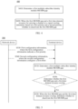
- FIG. 4 is a diagram of a communication method 400 according to an embodiment of this application. It should be understood that the communication method 400 may be performed by a communication device (for example, a network device or a terminal device), or may be performed by a chip or a circuit of the communication device, or may be implemented by a logical module or software that can implement all or a part of functions of the communication device. This is not limited in this application.
- a communication device for example, a network device or a terminal device
- a chip or a circuit of the communication device or may be implemented by a logical module or software that can implement all or a part of functions of the communication device. This is not limited in this application.
- an MUSIM may also be referred to as a multiple universal subscriber identity module (multiple universal subscriber identity module).
- a Chinese name of the MUSIM is not limited in embodiments of this application.
- the first MUSIM gap may be a periodic MUSIM gap, or may be an aperiodic MUSIM gap. This is not limited in embodiments of this application.
- S420 When the first MUSIM gap and a first time domain resource for carrying a channel or a signal overlap, determine, based on a first priority and a second priority, whether to deactivate (deactivate) the first MUSIM gap, where the first priority is a priority of the first MUSIM gap, and the second priority is a priority of the channel or the signal.
- resource overlapping is not a unique condition for determining, based on the first priority and the second priority, whether to deactivate the first MUSIM gap. That is, when the resource overlapping occurs, there may be an additional factor for determining, based on the first priority and the second priority, whether to deactivate the first MUSIM gap.
- the first MUSIM gap and the first time domain resource overlap may be that the first MUSIM gap and the first time domain resource completely or partially overlap.
- all time domain resources of the first MUSIM gap and the first time domain resource overlap or a part of time domain resources on which the first MUSIM gap and all time domain resources of the first time domain resource overlap and the first time domain resource overlap.
- a part of time domain resources of the first MUSIM gap and a part of time domain resources of the first time domain resource overlap may be that the first MUSIM gap and the first time domain resource completely or partially overlap.
- all time domain resources of the first MUSIM gap and the first time domain resource overlap or a part of time domain resources on which the first MUSIM gap and all time domain resources of the first time domain resource overlap and the first time domain resource overlap.
- a part of time domain resources of the first MUSIM gap and a part of time domain resources of the first time domain resource overlap may overlap.
- a unit of a time domain resource of an overlapping part between the first MUSIM gap and the first time domain resource may be a slot or a symbol.
- the first MUSIM gap is deactivated.
- That the terminal device deactivates the first MUSIM gap may be understood as that the terminal device deactivates all first MUSIM gaps. For example, if the first MUSIM gap is a periodic MUSIM gap, all MUSIM gap occasions (occasions) in a current period are deactivated.
- That the terminal device deactivates the first MUSIM gap may also be understood as that the terminal device deactivates an overlapping part of the first MUSIM gap, and the terminal device still maintains cell identification, measurement, or paging monitoring for a network B in a non-overlapping part.
- the first MUSIM gap when the first MUSIM gap is deactivated, transmission of a corresponding channel or signal is maintained on an overlapping part of the first time domain resource.
- the MUSIM gap and the first time domain resource overlap when the MUSIM gap and the first time domain resource overlap, whether to deactivate the MUSIM gap is determined based on the priority of the MUSIM gap and the priority of the channel or the signal on the first time domain resource. In comparison with a case in which it is considered by default that the MUSIM gap is in an active state, this preferentially ensures that cell identification, measurement, and paging monitoring are performed on the network B in a time period corresponding to the MUSIM gap.
- the foregoing solution can reduce impact on service data transmission, to improve service performance, especially for a delay-sensitive service, for example, an XR service.
- FIG. 5 is an interaction diagram of another communication method 500 according to an embodiment of this application.
- the communication method shown in FIG. 5 may be implemented mainly by a terminal device, or by a chip or a circuit of the terminal device, or the communication method 400 shown in FIG. 4 may be implemented by a logical module or software that can implement all or a part of functions of the terminal device.
- the communication method 500 includes the following steps.
- the network device in FIG. 5 may alternatively be a chip, a chip system, or a processor that supports the network device in implementing the corresponding method, or may be a logical module or software that can implement all or a part of functions of the network device.
- the terminal device in FIG. 5 may alternatively be a chip, a chip system, or a processor that supports the terminal device in implementing the corresponding method, or may be a logical module or software that can implement all or a part of functions of the terminal device.
- S510 The terminal device determines a first MUSIM gap.
- the terminal device determines a first time domain resource, where the first time domain resource is a time domain resource for carrying a channel or a signal.
- the terminal device determines the first MUSIM gap by using a gap length, a gap period, and a gap offset of the first MUSIM gap.
- the terminal device determines the first MUSIM gap, the terminal device considers by default that the first MUSIM gap is in an active state.
- the channel carried on the first time domain resource may be a first channel, for example, a physical uplink shared channel (physical uplink shared channel, PUSCH), a physical uplink control channel (physical uplink control channel, PUCCH), a physical downlink shared channel (physical downlink shared channel, PDSCH), or a physical downlink control channel (physical downlink control channel, PDCCH).
- a physical uplink shared channel physical uplink shared channel, PUSCH
- PUSCH physical uplink control channel
- PUCCH physical uplink control channel
- PUCCH physical downlink shared channel
- PDSCH physical downlink shared channel
- PDCCH physical downlink control channel
- the channel carried on the first time domain resource may alternatively be a second channel, for example, a logical channel carried in a media access control layer protocol data unit (media access control protocol data unit, MAC PDU) or a media access control layer control element (media access control control element, MAC CE).
- a media access control layer protocol data unit media access control protocol data unit, MAC PDU
- a media access control layer control element media access control control element, MAC CE
- the signal carried on the first time domain resource may be a channel state information reference signal (channel state information reference signal, CSI-RS) or a synchronization signal block (synchronization signal block, SSB) for downlink channel measurement, or may be a sounding reference signal (Sounding reference signal, SRS) for uplink channel measurement.
- CSI-RS channel state information reference signal
- SSB synchronization signal block
- SRS sounding reference signal
- the terminal device determines, based on a first priority and a second priority, whether to deactivate the first MUSIM gap.
- the first priority is a priority of the first MUSIM gap
- the second priority is a priority of the channel or the signal carried on the first time domain resource.
- the terminal device may determine the second priority based on a priority index (priority index) of the first channel.
- a priority of the first channel is a high priority, that is, the second priority is a high priority; or when a value of the priority index of the first channel is 0, a priority of the first channel is a low priority, that is, the second priority is a low priority.
- the terminal device may determine the second priority based on a highest priority of the second channel carried in the MAC PDU and an uplink priority threshold (ul-Prioritization Thres).
- ul-Prioritization Thres an uplink priority threshold
- the highest priority of the second channel is greater than or equal to the uplink priority threshold, it is determined that a priority of the second channel is a high priority, that is, the second priority is a high priority; or when the highest priority of the second channel is less than the uplink priority threshold, it is determined that a priority of the second channel is a low priority, that is, the second priority is a low priority.
- Table 1 There are four cases shown in Table 1 for the first priority and the second priority.
- Table 1 First priority Second priority Case 1 High priority High priority Case 2 High priority Low priority Case 3 Low priority High priority Case 4 Low priority Low priority
- the active state of the first MUSIM gap is maintained.
- the terminal device performs cell identification, measurement, or paging monitoring on a cell of a network B in the first MUSIM gap, and channel or signal transmission is not performed on an overlapping part of the first time domain resource.
- the active state of the first MUSIM gap is maintained.
- the first MUSIM gap is deactivated.
- the terminal device suspends performing cell identification, measurement, or paging monitoring on a cell of a network B in the first MUSIM gap, and channel or signal transmission is still performed on an overlapping part of the first time domain resource.
- the terminal device suspends performing cell identification, measurement, or paging monitoring on the cell of the network B in the first MUSIM gap, and still receives or sends the PUSCH, the PUCCH, the PDSCH, or the PDCCH on the overlapping part of the first time domain resource.
- the terminal device suspends performing cell identification, measurement, or paging monitoring on the cell of the network B in the first MUSIM gap, and still receives or sends the logical channel in the MAC PDU or the MAC CE on the overlapping part of the first time domain resource.
- the terminal device determines, at a first moment based on the first priority and the second priority, whether to deactivate the first MUSIM gap.
- the first moment is before a start moment of the first MUSIM gap, and a time interval between the first moment and the start moment is greater than or equal to a first offset.
- the terminal device performs a deactivation operation on the first MUSIM gap based on a priority determining result, or maintains the active state of the first MUSIM gap, so that service transmission performance can be effectively ensured.
- a priority of a related channel or signal of the delay-sensitive service is a high priority
- the priority of the first MUSIM gap is a low priority
- data transmission of the delay-sensitive service is maintained on a time domain overlapping part, so that transmission performance of the delay-sensitive service can be improved.
- the network device sends first configuration information to the terminal device, and the terminal device receives the first configuration information from the network device, where the first configuration information indicates the first priority.
- the terminal device determines the first priority based on the first configuration information.
- a first priority value and a first priority threshold of the first MUSIM gap may be configured based on the first configuration information; and the terminal device determines the first priority of the first MUSIM gap based on the first priority value and the first priority threshold.
- the first priority when the first priority value is greater than or equal to the first priority threshold, the first priority is a high priority; or when the first priority value is less than the first priority threshold, the first priority is a low priority.
- the first priority value may be a value within a range.
- the foregoing manner of determining the first priority by directly comparing the first priority value with the first priority threshold is merely an example.
- the first priority may be determined by using a difference or a ratio between the first priority value and the first priority threshold. This is not limited in embodiments of this application.
- a second priority value of the first MUSIM gap may be configured based on the first configuration information; and the terminal device determines the first priority of the first MUSIM gap based on the second priority value.
- the second priority value may have two fixed values, to represent that the first priority is a high priority or a low priority.
- a value representing the high priority or the low priority is not limited in embodiments of this application.
- the terminal device may preconfigure an index relationship between the second priority value and the high priority, and an index relationship between the second priority value and the low priority, so that the terminal device may determine the first priority based on the second priority value.
- the network device may send the first configuration information to the terminal device by using RRC signaling.
- the terminal device may further receive parameters such as the gap length, the gap period, and the gap offset of the first MUSIM gap by using the RRC signaling.
- the network device sends second configuration information to the terminal device, and the terminal device receives the second configuration information from the network device, where the second configuration information configures the first offset.
- the first offset indicates a time domain position at which the terminal device determines whether to deactivate the first MUSIM gap.
- the first offset is a minimum offset time period of the first moment at which the terminal device determines whether to deactivate the first MUSIM gap before the start moment of the first MUSIM gap.
- the first moment is determined based on the first offset and the start moment of the first MUSIM gap.
- the network device may send the second configuration information to the terminal device by using the RRC signaling.
- the terminal device determines in time whether to deactivate the first MUSIM gap, to reduce impact of a processing delay on the terminal device caused by carrier frequency switching required by the terminal device to perform inter-frequency measurement.
- the terminal device determines whether the first MUSIM gap and the first time domain resource overlap.
- the MUSIM gap and a time domain resource corresponding to a DRX timer may overlap. Specific scenarios are described in detail with reference to FIG. 6 to FIG. 8 .
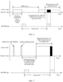
- FIG. 6 is a diagram of a conflict between an MUSIM gap and a time domain resource of a DRX timer according to an embodiment of this application.
- the terminal device when a terminal device is in an active state, the terminal device periodically monitors a PDCCH, and when the terminal device is in an inactive state, the terminal device does not monitor the PDCCH.
- the terminal device detects the PDCCH in a running duration of a DRX on duration timer (drx-onDurationTimer), and receives or sends data in a running duration of a DRX inactivity timer (drx-InactivityTimer) by starting or restarting the DRX inactivity timer.
- the terminal device In the running duration of the DRX inactivity timer, the terminal device is in the active state, and still needs to continuously monitor the PDCCH.
- a periodic MUSIM gap is used as an example. As shown in FIG. 6 , a 2 nd MUSIM gap and the running duration of the DRX inactivity timer overlap in time domain. An overlapping time domain resource shown in FIG. 6 indicates that an entire duration of the 2 nd MUSIM gap and a part of the duration of the DRX inactivity timer overlap.
- FIG. 7 is a diagram of another conflict between an MUSIM gap and a time domain resource of a DRX timer according to an embodiment of this application.
- a terminal device receives a PDCCH indicating downlink transmission, or receives a semi-persistent scheduling (semi-persistent scheduling, SPS) PDSCH.
- the terminal device fails to receive data, after sending a DRX uplink hybrid automatic repeat request negative acknowledgement (hybrid automatic repeat request negative acknowledgement, HARQ NACK), the terminal device starts a DRX HARQ round trip time downlink timer (drx-HARQ-RRT-TimerDL). After the DRX retransmission round trip time downlink timer expires, the terminal device starts a DRX retransmission downlink timer (drx-RetransmissionTimerDL). In a running duration of the DRX retransmission downlink timer, the terminal device is in an active state, and receives retransmission of the PDCCH and the PDSCH.
- the DRX HARQ round trip time downlink timer indicates a minimum duration in which the terminal device expects to receive indication information for HARQ retransmission. In other words, the terminal device does not expect to receive downlink retransmission indication information in a running duration of the DRX HARQ round trip time downlink timer.
- the DRX retransmission downlink timer indicates a maximum duration in which the terminal device receives the downlink retransmission indication information.
- a periodic MUSIM gap is used as an example.
- a 2 nd MUSIM gap and the running duration of the DRX retransmission downlink timer overlap in time domain.
- An overlapping time domain resource shown in FIG. 7 indicates that a part of a duration of the 2 nd MUSIM gap and a part of the duration of the DRX retransmission downlink timer overlap.
- FIG. 8 is a diagram of still another conflict between an MUSIM gap and a time domain resource of a DRX timer according to an embodiment of this application.
- a terminal device receives a PDCCH indicating uplink transmission or a configured grant (configured grant, CG) PUSCH, and after completing uplink PUSCH transmission, the terminal device starts a DRX HARQ round trip time uplink timer (drx-HARQ-RRT-TimerUL). After the DRX HARQ round trip time uplink timer expires, the terminal device starts a DRX retransmission uplink timer (drx-RetransmissionTimerUL). In a running duration of the DRX retransmission uplink timer, the terminal device is in an active state, and receives a PDCCH to indicate PUSCH retransmission.
- drx-HARQ-RRT-TimerUL DRX HARQ round trip time uplink timer
- the DRX HARQ round trip time uplink timer indicates a minimum duration in which the terminal device expects to receive indication information for HARQ retransmission. In other words, the terminal device does not expect to receive uplink retransmission indication information in a running duration of the DRX HARQ round trip time uplink timer.
- the DRX retransmission uplink timer indicates a maximum duration in which the terminal device receives the uplink retransmission indication information.
- a periodic MUSIM gap is used as an example.
- a 2 nd MUSIM gap and the running duration of the DRX retransmission uplink timer overlap in time domain.
- An overlapping time domain resource shown in FIG. 8 indicates that an entire duration of the 2 nd MUSIM gap and a part of the duration of the DRX retransmission uplink timer overlap.
- FIG. 9 is a diagram of still another communication method 900 according to an embodiment of this application. It should be understood that the communication method 900 may be performed by a communication device (for example, a network device or a terminal device), or may be performed by a chip or a circuit of the communication device, or may be implemented by a logical module or software that can implement all or a part of functions of the communication device. This is not limited in this application.
- a communication device for example, a network device or a terminal device
- a chip or a circuit of the communication device or may be implemented by a logical module or software that can implement all or a part of functions of the communication device. This is not limited in this application.
- S910 Determine a second multiple subscriber identity module MUSIM gap.
- the second MUSIM gap may be a periodic MUSIM gap, or may be an aperiodic MUSIM gap. This is not limited in embodiments of this application.
- S920 When the second MUSIM gap and a second time domain resource overlap, determine, based on a third priority and/or a fourth priority, whether to deactivate the second MUSIM gap, where a duration of the second time domain resource is a running duration of a first timer in discontinuous reception DRX, the third priority is a priority of the second MUSIM gap, and the fourth priority is a priority of a channel or a signal that triggers or is associated with starting or restarting of the first timer.
- the channel or the signal that triggers the starting or the restarting of the first timer indicates that the starting or the restarting of the first timer is directly triggered by the channel or the signal. This is described in detail below with reference to FIG. 10 .
- the signal or the signal that is associated with the starting or the restarting of the first timer indicates that the starting or the restarting of the first timer is indirectly triggered by the channel or the signal. This is described in detail below with reference to FIG. 10 .
- the second MUSIM gap is deactivated.
- the second MUSIM gap is deactivated.
- the first timer may be any one of a DRX inactivity timer, a DRX retransmission downlink timer, or a DRX retransmission uplink timer.
- the MUSIM gap and the second time domain resource overlap when the MUSIM gap and the second time domain resource overlap, whether to deactivate the MUSIM gap is determined based on the priority of the MUSIM gap and the priority of the channel or the signal that triggers or is associated with the starting or the restarting of the first timer. In comparison with a case in which it is considered by default that the MUSIM gap is in an active state, this preferentially ensures that cell identification, measurement, and paging monitoring are performed on a network B in a time period corresponding to the MUSIM gap.
- the foregoing solution can reduce impact on service data transmission, to improve service performance, especially for a delay-sensitive service, for example, an XR service.
- FIG. 10 is an interaction diagram of yet another communication method 1000 according to an embodiment of this application.
- the communication method shown in FIG. 10 may be implemented mainly by a terminal device, or by a chip or a circuit of the terminal device, or the communication method 900 shown in FIG. 9 may be implemented by a logical module or software that can implement all or a part of functions of the terminal device.
- the communication method 1000 includes the following steps.
- the network device in FIG. 10 may alternatively be a chip, a chip system, or a processor that supports the network device in implementing the corresponding method, or may be a logical module or software that can implement all or a part of functions of the network device.
- the terminal device in FIG. 10 may alternatively be a chip, a chip system, or a processor that supports the terminal device in implementing the corresponding method, or may be a logical module or software that can implement all or a part of functions of the terminal device.
- the terminal device determines a second MUSIM gap.
- the terminal device determines a second time domain resource, where a duration of the second time domain resource is a running duration of a first timer in DRX.
- the terminal device determines the second MUSIM gap by using a gap length, a gap period, and a gap offset of the second MUSIM gap.
- the terminal device determines the second MUSIM gap, the terminal device considers by default that the second MUSIM gap is in an active state.
- the first timer may be any one of a DRX inactivity timer, a DRX retransmission downlink timer, or a DRX retransmission uplink timer.
- the terminal device determines, based on a third priority and/or a fourth priority, whether to deactivate the second MUSIM gap.
- the third priority is a priority of the second MUSIM gap.
- the fourth priority is a priority of a channel or a signal that triggers starting or restarting of the first timer.
- the fourth priority is a priority of a channel or a signal that is associated with the first timer.
- the fourth priority is determined based on a value of a priority index of a PDCCH that triggers starting or restarting of the DRX inactivity timer during running of a DRX on duration timer.
- the priority index of the PDCCH that triggers the starting or the restarting of the DRX inactivity timer is 1, it is determined that the fourth priority is a high priority; or when the priority index of the PDCCH that is associated with the DRX inactivity timer is 0, it is determined that the fourth priority is a low priority.
- the fourth priority is determined based on a value of a priority index of any one of a PDCCH or an SPS PDSCH that is associated with starting or restarting of the DRX retransmission downlink timer, or a PUSCH that carries an uplink HARQ NACK.
- the DRX retransmission downlink timer is started after a DRX HARQ round trip time downlink timer expires, and the DRX HARQ round trip time downlink timer is triggered by using a PUSCH that is associated with a PDCCH or an SPS PDSCH and that carries an uplink HARQ NACK. Therefore, the fourth priority is related to a priority of any one of the PDCCH, the SPS PDSCH, or the PUSCH that carries the uplink HARQ NACK.
- the fourth priority is a high priority; or when the value of the priority index of the PDCCH that is associated with the DRX retransmission downlink timer is 0, the fourth priority is a low priority.
- the priority index value of the SPS PDSCH may be indicated by using a HARQ codebook identifier (harq-CodebookID) field.
- the fourth priority is determined based on a value of a priority index of any one of a PDCCH, a CG PDSCH, or a PUSCH that is associated with starting or restarting of the DRX retransmission uplink timer.
- a manner of determining the fourth priority by using the value of the priority index of the channel that is associated with the DRX retransmission uplink timer is similar to a manner of determining the fourth priority by using the value of the priority index of the channel that is associated with the DRX retransmission downlink timer. Details are not described herein again.
- the terminal device determines, at a second moment based on the third priority and the fourth priority, whether to deactivate the second MUSIM gap.
- the second moment is before a start moment of the second MUSIM gap, and a time interval between the second moment and the start moment is greater than or equal to a second offset.
- Table 2 There are four cases shown in Table 2 for the third priority and the fourth priority.
- Table 2 Third priority Fourth priority Case 5 High priority High priority Case 6 High priority Low priority Case 7 Low priority High priority Case 8 Low priority Low priority
- the terminal device deactivates the second MUSIM gap.
- the terminal device deactivates the second MUSIM gap.
- the terminal device determines to deactivate the second MUSIM gap.
- the terminal device when the DRX timer and the MUSIM gap overlap in time domain, the terminal device performs a deactivation operation on the second MUSIM gap based on a priority determining result, or maintains the active state of the second MUSIM gap, so that service transmission performance can be effectively ensured.
- a priority of a channel or a signal that triggers or that is associated with the timer is a high priority
- the priority of the second MUSIM gap is a low priority
- data transmission of the DRX timer is maintained on a time domain overlapping part, so that transmission performance of the delay-sensitive service can be improved.
- the network device sends third configuration information to the terminal device, and the terminal device receives the third configuration information from the network device, where the third configuration information indicates the third priority.
- the terminal device determines the third priority based on the third configuration information.
- a third priority value and a second priority threshold of the second MUSIM gap may be configured based on the third configuration information; and the terminal device determines the third priority of the second MUSIM gap based on the third priority value and the second priority threshold.
- a fourth priority value of the second MUSIM gap may be configured based on the third configuration information; and the terminal device determines the third priority of the second MUSIM gap based on the fourth priority value.
- the network device may send the third configuration information to the terminal device by using RRC signaling.
- the terminal device may further receive parameters such as the gap length, the gap period, and the gap offset of the second MUSIM gap by using the RRC signaling.
- the network device sends fourth configuration information to the terminal device, and the terminal device receives the fourth configuration information from the network device, where the fourth configuration information configures the second offset.
- the second moment is determined based on the second offset and the start moment of the second MUSIM gap.
- the terminal device determines in time whether to deactivate the second MUSIM gap, to reduce impact of a processing delay on the terminal device caused by carrier frequency switching required by the terminal device to perform inter-frequency measurement.
- the terminal device determines whether the second MUSIM gap and the second time domain resource overlap.
- FIG. 11 is an interaction diagram of still yet another communication method 1100 according to an embodiment of this application.
- the third time domain resource may be a time domain resource for transmitting a carried channel or signal between the network device and a terminal device.
- the third time domain resource may be equivalent to a first time domain resource.
- a duration of the third time domain resource may alternatively be a running duration of a DRX timer.
- the third time domain resource may be equivalent to a second time domain resource.
- the network device determines whether to deactivate the third MUSIM gap. This is not limited in embodiments of this application.
- the network device sends first downlink control information to the terminal device, and the terminal device receives the first downlink control information from the network device, where the first downlink control information indicates whether to deactivate the third MUSIM gap.
- the first downlink control information may be scheduling downlink control information (downlink control information, DCI).
- DCI downlink control information
- the scheduling DCI may be specifically a DCI format 0_0 (DCI format 0_0), a DCI format 0_1 (DCI format 0_1), a DCI format 0_2 (DCI format 0_2), a DCI format 1_1 (DCI format 1_1), or a DCI format 1_2 (DCI format 1_2).
- first indication information is added to the scheduling DCI.
- the first indication information indicates whether to deactivate the third MUSIM gap, or the first indication information indicates an occasion (occasion) of whether to deactivate one or more third MUSIM gaps, or the first indication information indicates an occasion of whether to deactivate one or more third MUSIM gaps in a first time period.
- the first downlink control information may alternatively be non-scheduling DCI.
- the non-scheduling DCI may be specifically a DCI format 2_6 (DCI format 2_6).
- second indication information is added to the non-scheduling DCI.
- the second indication information indicates whether to deactivate the third MUSIM gap, or the second indication information indicates an occasion (occasion) of whether to deactivate one or more third MUSIM gaps, or the second indication information indicates an occasion of whether to deactivate one or more third MUSIM gaps in a first time period, or the second indication information indicates an occasion of whether to deactivate one or more third MUSIM gaps in an (i+1) th DRX cycle.
- the terminal device may obtain the second indication information in an i th DRX cycle.
- the first downlink control information may alternatively be new DCI.
- the new DCI is scrambled by using a new radio network temporary identifier (radio network temporary identifier, RNTI).
- the new DCI includes third indication information.
- the third indication information indicates whether to deactivate the third MUSIM gap, or the third indication information indicates an occasion (occasion) of whether to deactivate one or more third MUSIM gaps, or the third indication information indicates an occasion of whether to deactivate one or more third MUSIM gaps in a first time period, or the third indication information indicates an occasion of whether to deactivate one or more third MUSIM gaps in an (i+1) th DRX cycle.
- the terminal device may obtain the third indication information in an i th DRX cycle.
- the network device sends the first downlink control information to the terminal device, and the terminal device receives the first downlink control information from the network device.
- the third moment is before a start moment of the third MUSIM gap, and a time interval between the third moment and the start moment is greater than or equal to a third offset.
- the third offset is determined by the network device.
- the terminal device deactivates the third MUSIM gap or maintains an active state of the third MUSIM gap based on the first downlink control information.
- the network device dynamically indicates, by using the downlink control information, the terminal device whether to deactivate the third MUSIM gap, so that the terminal device can more flexibly choose to continue to perform service data transmission with a network A on an overlapping part of the time domain resource, or perform cell identification, measurement, or paging monitoring on a cell of a network B.
- FIG. 15 is a schematic flowchart of a further communication method 1500 according to an embodiment of this application. It should be understood that the communication method 1500 may be performed by a communication device (for example, a network device or a terminal device), or may be performed by a chip or a circuit of the communication device, or may be implemented by a logical module or software that can implement all or a part of functions of the communication device. This is not limited in this application.
- a communication device for example, a network device or a terminal device
- a chip or a circuit of the communication device or may be implemented by a logical module or software that can implement all or a part of functions of the communication device. This is not limited in this application.
- S1510 Determine a first multiple subscriber identity module MUSIM gap.
- S1520 When the first MUSIM gap and a first time domain resource for carrying a channel or a signal overlap, determine, based on a first priority and a second priority, whether to deactivate the first MUSIM gap is determined.
- S1510 and S1520 are similar to S410 and S420. Details are not described herein again.
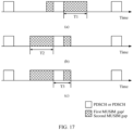
- S1530a Perform MUSIM gap measurement in a non-overlapping time period between the first MUSIM gap and the first time domain resource, and deactivate a part of the first MUSIM gap.
- deactivating the part of the first MUSIM gap may be deactivating a time period in which the first MUSIM gap and the first time domain resource overlap, or may be deactivating a time period in which MUSIM gap measurement is not performed.
- FIG. 17 is a diagram of MUSIM gap measurement according to an embodiment of this application.
- MUSIM gap measurement is performed, where the non-overlapping time period includes a time period from a start moment of the first MUSIM gap to a start moment of the first time domain resource.
- deactivating the part of the first MUSIM gap may be deactivating a time period from the start moment of the first MUSIM gap to an end moment of the first time domain resource.
- MUSIM gap measurement is performed, where the non-overlapping time period includes a time period from the end moment of the first time domain resource to an end moment of the first MUSIM gap.
- deactivating the part of the first MUSIM gap may be deactivating a time period from the start moment of the first time domain resource to the end moment of the first MUSIM gap.
- S1530b When a time period from the start moment of the first MUSIM gap to the end moment of the first MUSIM gap is less than a third threshold, perform MUSIM gap measurement on a part of the first MUSIM gap.
- the part of the first MUSIM gap may be the time period from the start moment of the first MUSIM gap to the end moment of the first MUSIM gap.
- the part of the first MUSIM gap may be an entire first MUSIM gap.
- any one of the first threshold, the second threshold, or the third threshold may be configured by the network device for the terminal device by using RRC signaling, and values of the first threshold, the second threshold, and the third threshold may be the same or may be different. This is not limited in embodiments of this application.
- time periods in S1530a and S1530b meet any one or more of the first threshold, the second threshold, or the third threshold, and MUSIM gap measurement may be performed in both the time periods that meet the condition.
- FIG. 16 is a schematic flowchart of a still further communication method 1600 according to an embodiment of this application.
- the communication method 1600 may be performed by a communication device (for example, a network device or a terminal device), or may be performed by a chip or a circuit of the communication device, or may be implemented by a logical module or software that can implement all or a part of functions of the communication device. This is not limited in this application.
- S1620 When the second MUSIM gap and a second time domain resource overlap, determine, based on a third priority and/or a fourth priority, whether to deactivate the second MUSIM gap, where a duration of the second time domain resource is a running duration of a first timer in discontinuous reception DRX, the third priority is a priority of the second MUSIM gap, and the fourth priority is a priority of a channel or a signal that triggers or is associated with starting or restarting of the first timer.
- S1610 and S1620 are similar to S910 and S920. Details are not described herein again.
- S1630a Perform MUSIM gap measurement in a non-overlapping time period between the second MUSIM gap and the second time domain resource, and deactivate a time period of the second MUSIM gap in which MUSIM gap measurement is not performed.
- S1630b When a time period from a start moment of the second MUSIM gap to an end moment of the second MUSIM gap is less than a third threshold, perform MUSIM gap measurement on a part of the second MUSIM gap.
- S1630a is similar to S1530a
- S1630b is similar to S1530b. Details are not described herein again.
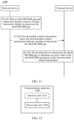
- FIG. 12 is a diagram of a communication apparatus 1200 according to an embodiment of this application.
- the apparatus 1200 may include a processing unit 1220, and the processing unit 1220 may be configured to process data.
- the apparatus 1200 may further include an interface unit 1210.
- the interface unit 1210 may implement a corresponding communication function.
- the interface unit 1210 may also be referred to as a communication interface, a communication unit, or a transceiver unit. It should be understood that unless otherwise specified, or if operations such as sending and receiving in this application do not contradict an actual function or internal logic of the operations in related descriptions, the operations may be more generally understood as operations such as outputting and inputting, instead of operations of sending and receiving directly performed by a radio frequency circuit and an antenna.
- the apparatus 1200 may further include a storage unit.
- the storage unit may be configured to store instructions and/or data.
- the processing unit 1220 may read the instructions and/or the data in the storage unit, to enable the apparatus to implement the foregoing method embodiments.
- the apparatus 1200 may be configured to perform an action performed by the communication device (for example, a network device or a terminal device) in the foregoing method embodiments.
- the apparatus 1200 may be a communication device or a component that can be configured in the communication device.
- the interface unit 1210 is configured to perform sending/receiving-related operations on a communication device side in the foregoing method embodiments
- the processing unit 1220 is configured to perform processing-related operations on the communication device side in the foregoing method embodiments.
- the apparatus 1200 is configured to perform an action performed by the network device or the terminal device in the method embodiment shown in FIG. 4 .
- the processing unit 1220 is configured to determine a first multiple subscriber identity module MUSIM gap.
- the processing unit 1220 is configured to: when the first MUSIM gap and a first time domain resource for carrying a channel or a signal overlap, determine, based on a first priority and a second priority, whether to deactivate the first MUSIM gap, where the first priority is a priority of the first MUSIM gap, and the second priority is a priority of a channel or a signal.
- the processing unit 1220 is configured to deactivate the first MUSIM gap when the first priority is a low priority and the second priority is a high priority.
- the apparatus 1200 further includes an interface unit 1210, and the interface unit 1210 is configured to receive first configuration information.
- the processing unit 1220 is further configured to determine the first priority based on the first configuration information.
- processing unit 1220 is further configured to determine the first priority based on the first configuration information includes: A first priority value and a first priority threshold of the first MUSIM gap are configured based on the first configuration information.
- the processing unit is configured to determine the first priority based on the first priority value and the first priority threshold.
- processing unit 1220 is further configured to determine the first priority based on the first configuration information includes: configuring a second priority value of the first MUSIM gap based on the first configuration information.
- the processing unit 1220 is configured to determine the first priority based on the second priority value.
- the interface unit 1210 is further configured to receive second configuration information, where the second configuration information configures a first offset. That the processing unit 1220 is configured to determine whether to deactivate the first MUSIM gap includes: The processing unit 1220 is configured to determine, at a first moment, whether to deactivate the first MUSIM gap, where the first moment is before a start moment of the first MUSIM gap, and a time interval between the first moment and the start moment is greater than or equal to the first offset.
- the apparatus 1200 is configured to perform an action performed by the network device or the terminal device in the method embodiment shown in FIG. 15 .
- processing unit 1220 is configured to determine whether to deactivate the first MUSIM gap includes: performing MUSIM gap measurement in a non-overlapping time period between the first MUSIM gap and the first time domain resource, and deactivating a part of the first MUSIM gap.
- processing unit 1220 is configured to perform MUSIM gap measurement includes: when the non-overlapping time period is greater than a first threshold, performing MUSIM gap measurement, where the non-overlapping time period includes a time period from the start moment of the first MUSIM gap to a start moment of the first time domain resource.
- processing unit 1220 is configured to perform MUSIM gap measurement includes: when the non-overlapping time period is greater than a second threshold, performing MUSIM gap measurement, where the non-overlapping time period includes a time period from an end moment of the first time domain resource to an end moment of the first MUSIM gap.
- processing unit 1220 is configured to determine whether to deactivate the first MUSIM gap includes: when a time period from a start moment of the first time domain resource to an end moment of the first MUSIM gap is less than a third threshold, performing MUSIM gap measurement on a part of the first MUSIM gap.
- the apparatus 1200 is configured to perform an action performed by the network device or the terminal device in the method embodiment shown in FIG. 9 .
- the processing unit 1220 is configured to determine a second multiple subscriber identity module MUSIM gap.
- the processing unit 1220 is configured to: when the second MUSIM gap and a second time domain resource overlap, determine, based on a third priority and/or a fourth priority, whether to deactivate the second MUSIM gap, where a duration of the second time domain resource is a running duration of a first timer in discontinuous reception, the third priority is a priority of the second MUSIM gap, and the fourth priority is a priority of a channel or a signal that triggers or is associated with starting or restarting of the first timer.
- processing unit 1220 is configured to determine, based on a third priority and/or a fourth priority, whether to deactivate the second MUSIM gap includes: when the third priority is a low priority and the fourth priority is a high priority, deactivating the second MUSIM gap.
- processing unit 1220 is configured to determine, based on a third priority and/or a fourth priority, whether to deactivate the second MUSIM gap includes: deactivating the second MUSIM gap when the third priority is a low priority.
- processing unit 1220 is configured to determine, based on a third priority and/or a fourth priority, whether to deactivate the second MUSIM gap includes: deactivating the second MUSIM gap when the fourth priority is a high priority.
- the apparatus 1200 further includes an interface unit 1210, and the interface unit 1210 is configured to receive third configuration information.
- the processing unit 1220 is further configured to determine the third priority based on the third configuration information.
- processing unit 1220 is further configured to determine the third priority based on the third configuration information includes: A third priority value and a second priority threshold of the second MUSIM gap are configured based on the third configuration information.
- the processing unit 1220 is further configured to determine the third priority based on the third priority value and the second priority threshold.
- processing unit 1220 is further configured to determine the third priority based on the third configuration information includes: configuring a fourth priority value of the second MUSIM gap based on the third configuration information.
- the processing unit 1220 is further configured to determine the third priority based on the fourth priority value.
- the interface unit 1210 is further configured to receive fourth configuration information, where the fourth configuration information configures a second offset.
- the processing unit 1220 is further configured to determine, at a second moment, whether to deactivate the second MUSIM gap, where the second moment is before a start moment of the second MUSIM gap, and a time interval between the second moment and the start moment is greater than or equal to the second offset.
- the apparatus 1200 is configured to perform an action performed by the network device or the terminal device in the method embodiment shown in FIG. 16 .
- processing unit 1220 is configured to determine whether to deactivate a second MUSIM gap includes: performing MUSIM gap measurement in a non-overlapping time period between the second MUSIM gap and a first time domain resource, and deactivating a part of the second MUSIM gap.
- processing unit 1220 is configured to perform MUSIM gap measurement includes: when the non-overlapping time period is greater than a first threshold, performing MUSIM gap measurement, where the non-overlapping time period includes a time period from a start moment of the second MUSIM gap to a start moment of a second time domain resource.
- processing unit 1220 is configured to perform MUSIM gap measurement includes: when the non-overlapping time period is greater than a second threshold, performing MUSIM gap measurement, where the non-overlapping time period includes a time period from an end moment of the second time domain resource to an end moment of the second MUSIM gap.
- processing unit 1220 is configured to determine whether to deactivate a second MUSIM gap includes: when a time period from a start moment of a second time domain resource to an end moment of the second MUSIM gap is less than a third threshold, performing MUSIM gap measurement on a part of the second MUSIM gap.
- the apparatus 1200 may implement steps or procedures performed by the terminal device or the network device in the method embodiments according to embodiments of this application.
- the apparatus 1200 may include units configured to perform the methods performed by the terminal device or the network device in FIG. 5 , FIG. 10 , and FIG. 11 .
- the units in the apparatus 1200 and the foregoing other operations and/or functions are respectively used to implement corresponding procedures of the network device in the method embodiments in FIG. 5 , FIG. 10 , and FIG. 11 .
- the interface unit 1210 may be configured to perform S530 and S540 in the method 500
- the processing unit 1220 may be configured to perform processing steps in the method 500, for example, S510, S520, and S550.
- the interface unit 1210 may be configured to perform S1030 and S1040 in the method 500
- the processing unit 1220 may be configured to perform processing steps in the method 1000, for example, S1010, S1020, and S1050.
- the interface unit 1210 may be configured to perform S1120 in the method 500, and the processing unit 1220 may be configured to perform processing steps in the method 1100, for example, S1110 and S1130.
- the processing unit 1220 in the foregoing embodiments may be implemented by at least one processor or a processor-related circuit.
- the interface unit 1210 may be implemented by a transceiver or a transceiver-related circuit.
- the storage unit may be implemented by at least one memory.
- FIG. 13 is a diagram of a structure of a communication apparatus 1300 according to an embodiment of this application.
- an embodiment of this application further provides a communication apparatus 1300.
- the apparatus 1300 includes a processor 1310.
- the processor 1310 is coupled to a memory 1320, the memory 1320 is configured to store a computer program or instructions and/or data, and the processor 1310 is configured to execute the computer program or the instructions and/or the data stored in the memory 1320, so that the methods in the foregoing method embodiments are performed.
- the apparatus 1300 includes one or more processors 1310.
- the apparatus 1300 may further include the memory 1320.
- the apparatus 1300 may include one or more memories 1320.
- the memory 1320 and the processor 1310 may be integrated, or disposed separately.
- the apparatus 1300 may further include a transceiver 1330.
- the transceiver 1330 is configured to receive and/or send a signal.
- the processor 1310 is configured to control the transceiver 1330 to receive and/or send a signal.
- the apparatus 1300 is configured to implement operations performed by the communication device (for example, the network device or the terminal device) in the foregoing method embodiments.
- the communication device for example, the network device or the terminal device
- the processor 1310 is configured to implement processing-related operations performed by the network device or the terminal device in the foregoing method embodiments
- the transceiver 1330 is configured to implement transceiver-related operations performed by the network device or the terminal device in the foregoing method embodiments.
- FIG. 14 is a diagram of a chip system 1400 according to an embodiment of this application.
- the chip system 1400 (or may be referred to as a processing system) includes a logic circuit 1410 and an input/output interface (input/output interface) 1420.
- the logic circuit is configured to be coupled to the input interface, and transmit a data parameter through the input/output interface, to perform the methods in the foregoing method embodiments.
- a device in which the chip system 1400 is installed may implement the methods and functions in embodiments of this application.
- the logic circuit 1410 may be a processing circuit in the chip system 1400, to control the device in which the chip system 1400 is installed, or may be coupled to a storage unit, and invoke instructions in the storage unit, so that the device can implement the methods and functions in embodiments of this application.
- the input/output interface 1420 may be an input/output circuit in the chip system 1400, to output information processed by the chip system 1400, or input to-be-processed data or signaling information to the chip system 1400 for processing.
- the chip system 1400 is configured to implement operations performed by the communication device (for example, the network device or the terminal device) in the foregoing method embodiments.
- the logic circuit 1410 is configured to implement processing-related operations performed by the network device or the terminal device in the foregoing method embodiments
- the input/output interface 1420 is configured to implement transceiver-related operations performed by the network device or the terminal device in the foregoing method embodiments.
- An embodiment of this application further provides a computer-readable storage medium.
- the computer-readable storage medium stores computer instructions for implementing the method performed by the communication device (for example, the network device or the terminal device) in the foregoing method embodiments.
- the computer when a computer program is executed by a computer, the computer is enabled to implement the method performed by the first communication device in the foregoing method embodiments.
- An embodiment of this application further provides a computer program product including instructions.
- the instructions When the instructions are executed by a computer, the computer is enabled to implement the method performed by the communication device (for example, the network device, or the terminal device) in the foregoing method embodiments.
- the processor mentioned in embodiments of this application may be a central processing unit (central processing unit, CPU), and may further be another general-purpose processor, a digital signal processor (digital signal processor, DSP), an application-specific integrated circuit (application-specific integrated circuit, ASIC), a field programmable gate array (field programmable gate array, FPGA) or another programmable logic device, a discrete gate or a transistor logic device, a discrete hardware component, or the like.
- the general-purpose processor may be a microprocessor, or the processor may be any conventional processor or the like.
- the memory mentioned in embodiments of this application may be a volatile memory and/or a non-volatile memory.
- the non-volatile memory may be a read-only memory (read-only memory, ROM), a programmable read-only memory (programmable ROM, PROM), an erasable programmable read-only memory (erasable PROM, EPROM), an electrically erasable programmable read-only memory (electrically EPROM, EEPROM), or a flash memory.
- the volatile memory may be a random access memory (random access memory, RAM).
- the RAM may be used as an external cache.
- the RAM may include the following plurality of forms: a static random access memory (static RAM, SRAM), a dynamic random access memory (dynamic RAM, DRAM), a synchronous dynamic random access memory (synchronous DRAM, SDRAM), a double data rate synchronous dynamic random access memory (double data rate SDRAM, DDR SDRAM), an enhanced synchronous dynamic random access memory (enhanced SDRAM, ESDRAM), a synchlink dynamic random access memory (synchlink DRAM, SLDRAM), and a direct rambus random access memory (direct rambus RAM, DR RAM).
- static random access memory static random access memory
- DRAM dynamic random access memory
- DRAM synchronous dynamic random access memory
- SDRAM double data rate synchronous dynamic random access memory
- double data rate SDRAM double data rate SDRAM
- ESDRAM enhanced synchronous dynamic random access memory
- synchlink dynamic random access memory synchlink dynamic random access memory
- direct rambus RAM direct rambus RAM, DR RAM
- processor when the processor is a general-purpose processor, a DSP, an ASIC, an FPGA or another programmable logic device, a discrete gate or a transistor logic device, or a discrete hardware component, a memory (storage module) may be integrated into the processor.
- the memory described in this specification is intended to include, but is not limited to, these memories and any other memory of a suitable type.
- the disclosed apparatus and method may be implemented in other manners.
- the described apparatus embodiments are merely examples.
- division into the units is merely logical function division.
- a plurality of units or components may be combined or integrated into another system, or some features may be ignored or not performed.
- the displayed or discussed mutual couplings or direct couplings or communication connections may be implemented through some interfaces.
- the indirect couplings or communication connections between the apparatuses or units may be implemented in electronic, mechanical, or other forms.
- the units described as separate parts may or may not be physically separate, and parts displayed as units may or may not be physical units, in other words, may be located in one position, or may be distributed on a plurality of network units. A part or all of the units may be selected based on actual requirements to implement the solutions provided in this application.
- All or a part of the foregoing embodiments may be implemented by using software, hardware, firmware, or any combination thereof.
- all or a part of embodiments may be implemented in a form of a computer program product.
- the computer program product includes one or more computer instructions.
- the computer may be a general-purpose computer, a dedicated computer, a computer network, or other programmable apparatuses.
- the computer may be a personal computer, a server, or a network device.
- the computer instructions may be stored in a computer-readable storage medium or may be transmitted from a computer-readable storage medium to another computer-readable storage medium.
- the computer instructions may be transmitted from a website, computer, server, or data center to another website, computer, server, or data center in a wired (for example, a coaxial cable, an optical fiber, or a digital subscriber line (DSL)) or wireless (for example, infrared, radio, or microwave) manner.
- the computer-readable storage medium may be any usable medium accessible by a computer, or a data storage device, such as a server or a data center, integrating one or more usable media.
- the usable medium may be a magnetic medium (for example, a floppy disk, a hard disk drive, or a magnetic tape), an optical medium (for example, a DVD), a semiconductor medium (for example, a solid-state drive (solid-state drive, SSD)), or the like.
- the foregoing usable media may include but are not limited to: any medium that can store program code, for example, a USB flash drive, a removable hard disk drive, a read-only memory (read-only memory, ROM), a random access memory (random access memory, RAM), a magnetic disk, or an optical disc.
Landscapes
- Engineering & Computer Science (AREA)
- Computer Networks & Wireless Communication (AREA)
- Signal Processing (AREA)
- Mobile Radio Communication Systems (AREA)
Applications Claiming Priority (3)
| Application Number | Priority Date | Filing Date | Title |
|---|---|---|---|
| CN202211196995 | 2022-09-28 | ||
| CN202310247905.8A CN117793933A (zh) | 2022-09-28 | 2023-03-07 | 一种musim间隙的处理方法和装置 |
| PCT/CN2023/118407 WO2024067081A1 (fr) | 2022-09-28 | 2023-09-13 | Procédé et dispositif de traitement d'intervalle musim |
Publications (2)
| Publication Number | Publication Date |
|---|---|
| EP4561234A1 true EP4561234A1 (fr) | 2025-05-28 |
| EP4561234A4 EP4561234A4 (fr) | 2025-11-12 |
Family
ID=90400538
Family Applications (1)
| Application Number | Title | Priority Date | Filing Date |
|---|---|---|---|
| EP23870318.5A Pending EP4561234A4 (fr) | 2022-09-28 | 2023-09-13 | Procédé et dispositif de traitement d'intervalle musim |
Country Status (4)
| Country | Link |
|---|---|
| US (1) | US20250203709A1 (fr) |
| EP (1) | EP4561234A4 (fr) |
| CN (1) | CN117793933A (fr) |
| WO (1) | WO2024067081A1 (fr) |
Families Citing this family (1)
| Publication number | Priority date | Publication date | Assignee | Title |
|---|---|---|---|---|
| US20250176021A1 (en) * | 2023-11-28 | 2025-05-29 | Qualcomm Incorporated | Multiple user subscriber identity module gap signaling |
Family Cites Families (6)
| Publication number | Priority date | Publication date | Assignee | Title |
|---|---|---|---|---|
| CN103167610B (zh) * | 2011-12-12 | 2017-10-13 | 安华高科技通用Ip(新加坡)公司 | 用于多sim用户设备的智能资源控制 |
| US20170230932A1 (en) * | 2016-02-04 | 2017-08-10 | Qualcomm Incorporated | Paging conflict management for multi-sim wireless communication device |
| US11765717B2 (en) * | 2020-05-27 | 2023-09-19 | Qualcomm Incorporated | Enhanced coordination of communication on links for multiple subscriber identification modules (SIMs) |
| WO2022026173A1 (fr) * | 2020-07-28 | 2022-02-03 | Qualcomm Incorporated | Commande d'intervalle de mesure dynamique |
| CN114650620B (zh) * | 2020-12-18 | 2025-08-22 | 夏普株式会社 | 用户设备的连接方法以及用户设备 |
| CN115038098B (zh) * | 2021-03-04 | 2026-03-03 | 维沃移动通信有限公司 | 间隙gap处理方法、装置、设备及存储介质 |
-
2023
- 2023-03-07 CN CN202310247905.8A patent/CN117793933A/zh active Pending
- 2023-09-13 EP EP23870318.5A patent/EP4561234A4/fr active Pending
- 2023-09-13 WO PCT/CN2023/118407 patent/WO2024067081A1/fr not_active Ceased
-
2025
- 2025-02-25 US US19/062,033 patent/US20250203709A1/en active Pending
Also Published As
| Publication number | Publication date |
|---|---|
| CN117793933A (zh) | 2024-03-29 |
| WO2024067081A1 (fr) | 2024-04-04 |
| US20250203709A1 (en) | 2025-06-19 |
| EP4561234A4 (fr) | 2025-11-12 |
Similar Documents
| Publication | Publication Date | Title |
|---|---|---|
| EP4369797A1 (fr) | Procédé et appareil de configuration drx, dispositif terminal et dispositif de réseau | |
| US11937324B2 (en) | Data transmitting/receiving apparatuses and methods and communication system | |
| US11134523B2 (en) | Uplink transmission control method and apparatus and communication system | |
| EP4539577A1 (fr) | Procédé et appareil de transmission basés sur la priorité | |
| CN110912663B (zh) | 一种通信方法及装置 | |
| WO2018196520A1 (fr) | Procédé de gestion de faisceau, dispositif terminal et dispositif de réseau | |
| EP3972351B1 (fr) | Procédé d'économie d'énergie, dispositif terminal et dispositif de réseau | |
| US20190229777A1 (en) | Beam recovery method and apparatus | |
| US11330442B2 (en) | Signal transmission method and apparatus | |
| US20230141380A1 (en) | Method and apparatus for sidelink resource re-evaluation | |
| KR102501134B1 (ko) | 무선 통신들에서의 유연한 다운링크 제어 신호 모니터링 | |
| US12550054B2 (en) | Mobility for small data transmission procedure | |
| US12295042B2 (en) | Communication method and apparatus | |
| US12550227B2 (en) | Timer operating method, terminal device, and network device | |
| KR20210083278A (ko) | Pdcch의 모니터링 방법과 장치 | |
| EP4568345A1 (fr) | Procédé et appareil de communication | |
| US20220167380A1 (en) | Communication Method And Apparatus | |
| US20250203709A1 (en) | Musim gap processing method and apparatus | |
| US20220217701A1 (en) | Wireless communication method and apparatus and communication system | |
| WO2021092776A1 (fr) | Procédé de traitement de réception discontinue et dispositif terminal | |
| US11864112B2 (en) | Apparatus, method and computer program | |
| EP4503804A1 (fr) | Procédé et appareil de transmission de données | |
| WO2021072608A1 (fr) | Procédé et appareil permettant de notifier un décalage d'unité de temps minimal |
Legal Events
| Date | Code | Title | Description |
|---|---|---|---|
| STAA | Information on the status of an ep patent application or granted ep patent |
Free format text: STATUS: THE INTERNATIONAL PUBLICATION HAS BEEN MADE |
|
| PUAI | Public reference made under article 153(3) epc to a published international application that has entered the european phase |
Free format text: ORIGINAL CODE: 0009012 |
|
| STAA | Information on the status of an ep patent application or granted ep patent |
Free format text: STATUS: REQUEST FOR EXAMINATION WAS MADE |
|
| 17P | Request for examination filed |
Effective date: 20250221 |
|
| AK | Designated contracting states |
Kind code of ref document: A1 Designated state(s): AL AT BE BG CH CY CZ DE DK EE ES FI FR GB GR HR HU IE IS IT LI LT LU LV MC ME MK MT NL NO PL PT RO RS SE SI SK SM TR |
|
| REG | Reference to a national code |
Ref country code: DE Ref legal event code: R079 Free format text: PREVIOUS MAIN CLASS: H04W0072044600 Ipc: H04W0076280000 |
|
| A4 | Supplementary search report drawn up and despatched |
Effective date: 20251015 |
|
| RIC1 | Information provided on ipc code assigned before grant |
Ipc: H04W 76/28 20180101AFI20251009BHEP Ipc: H04W 8/18 20090101ALN20251009BHEP |
|
| DAV | Request for validation of the european patent (deleted) | ||
| DAX | Request for extension of the european patent (deleted) |