EP4562989A1 - Véhicule agricole à fonctionnement et sécurité améliorés, et procédés associés - Google Patents
Véhicule agricole à fonctionnement et sécurité améliorés, et procédés associés Download PDFInfo
- Publication number
- EP4562989A1 EP4562989A1 EP24207407.8A EP24207407A EP4562989A1 EP 4562989 A1 EP4562989 A1 EP 4562989A1 EP 24207407 A EP24207407 A EP 24207407A EP 4562989 A1 EP4562989 A1 EP 4562989A1
- Authority
- EP
- European Patent Office
- Prior art keywords
- lidar
- image data
- data
- vehicle
- agricultural
- Prior art date
- Legal status (The legal status is an assumption and is not a legal conclusion. Google has not performed a legal analysis and makes no representation as to the accuracy of the status listed.)
- Pending
Links
Images


Classifications
-
- G—PHYSICS
- G06—COMPUTING OR CALCULATING; COUNTING
- G06V—IMAGE OR VIDEO RECOGNITION OR UNDERSTANDING
- G06V20/00—Scenes; Scene-specific elements
- G06V20/50—Context or environment of the image
- G06V20/56—Context or environment of the image exterior to a vehicle by using sensors mounted on the vehicle
-
- A—HUMAN NECESSITIES
- A01—AGRICULTURE; FORESTRY; ANIMAL HUSBANDRY; HUNTING; TRAPPING; FISHING
- A01B—SOIL WORKING IN AGRICULTURE OR FORESTRY; PARTS, DETAILS, OR ACCESSORIES OF AGRICULTURAL MACHINES OR IMPLEMENTS, IN GENERAL
- A01B69/00—Steering of agricultural machines or implements; Guiding agricultural machines or implements on a desired track
- A01B69/001—Steering by means of optical assistance, e.g. television cameras
-
- A—HUMAN NECESSITIES
- A01—AGRICULTURE; FORESTRY; ANIMAL HUSBANDRY; HUNTING; TRAPPING; FISHING
- A01B—SOIL WORKING IN AGRICULTURE OR FORESTRY; PARTS, DETAILS, OR ACCESSORIES OF AGRICULTURAL MACHINES OR IMPLEMENTS, IN GENERAL
- A01B69/00—Steering of agricultural machines or implements; Guiding agricultural machines or implements on a desired track
- A01B69/007—Steering or guiding of agricultural vehicles, e.g. steering of the tractor to keep the plough in the furrow
- A01B69/008—Steering or guiding of agricultural vehicles, e.g. steering of the tractor to keep the plough in the furrow automatic
-
- G—PHYSICS
- G01—MEASURING; TESTING
- G01S—RADIO DIRECTION-FINDING; RADIO NAVIGATION; DETERMINING DISTANCE OR VELOCITY BY USE OF RADIO WAVES; LOCATING OR PRESENCE-DETECTING BY USE OF THE REFLECTION OR RERADIATION OF RADIO WAVES; ANALOGOUS ARRANGEMENTS USING OTHER WAVES
- G01S17/00—Systems using the reflection or reradiation of electromagnetic waves other than radio waves, e.g. lidar systems
- G01S17/86—Combinations of lidar systems with systems other than lidar, radar or sonar, e.g. with direction finders
-
- G—PHYSICS
- G01—MEASURING; TESTING
- G01S—RADIO DIRECTION-FINDING; RADIO NAVIGATION; DETERMINING DISTANCE OR VELOCITY BY USE OF RADIO WAVES; LOCATING OR PRESENCE-DETECTING BY USE OF THE REFLECTION OR RERADIATION OF RADIO WAVES; ANALOGOUS ARRANGEMENTS USING OTHER WAVES
- G01S17/00—Systems using the reflection or reradiation of electromagnetic waves other than radio waves, e.g. lidar systems
- G01S17/88—Lidar systems specially adapted for specific applications
- G01S17/89—Lidar systems specially adapted for specific applications for mapping or imaging
-
- G—PHYSICS
- G01—MEASURING; TESTING
- G01S—RADIO DIRECTION-FINDING; RADIO NAVIGATION; DETERMINING DISTANCE OR VELOCITY BY USE OF RADIO WAVES; LOCATING OR PRESENCE-DETECTING BY USE OF THE REFLECTION OR RERADIATION OF RADIO WAVES; ANALOGOUS ARRANGEMENTS USING OTHER WAVES
- G01S17/00—Systems using the reflection or reradiation of electromagnetic waves other than radio waves, e.g. lidar systems
- G01S17/88—Lidar systems specially adapted for specific applications
- G01S17/93—Lidar systems specially adapted for specific applications for anti-collision purposes
- G01S17/931—Lidar systems specially adapted for specific applications for anti-collision purposes of land vehicles
-
- G—PHYSICS
- G05—CONTROLLING; REGULATING
- G05D—SYSTEMS FOR CONTROLLING OR REGULATING NON-ELECTRIC VARIABLES
- G05D1/00—Control of position, course, altitude or attitude of land, water, air or space vehicles, e.g. using automatic pilots
- G05D1/20—Control system inputs
- G05D1/24—Arrangements for determining position or orientation
- G05D1/242—Means based on the reflection of waves generated by the vehicle
-
- G—PHYSICS
- G05—CONTROLLING; REGULATING
- G05D—SYSTEMS FOR CONTROLLING OR REGULATING NON-ELECTRIC VARIABLES
- G05D1/00—Control of position, course, altitude or attitude of land, water, air or space vehicles, e.g. using automatic pilots
- G05D1/20—Control system inputs
- G05D1/24—Arrangements for determining position or orientation
- G05D1/243—Means capturing signals occurring naturally from the environment, e.g. ambient optical, acoustic, gravitational or magnetic signals
-
- G—PHYSICS
- G05—CONTROLLING; REGULATING
- G05D—SYSTEMS FOR CONTROLLING OR REGULATING NON-ELECTRIC VARIABLES
- G05D1/00—Control of position, course, altitude or attitude of land, water, air or space vehicles, e.g. using automatic pilots
- G05D1/60—Intended control result
- G05D1/617—Safety or protection, e.g. defining protection zones around obstacles or avoiding hazards
- G05D1/622—Obstacle avoidance
-
- G—PHYSICS
- G06—COMPUTING OR CALCULATING; COUNTING
- G06T—IMAGE DATA PROCESSING OR GENERATION, IN GENERAL
- G06T7/00—Image analysis
- G06T7/50—Depth or shape recovery
- G06T7/55—Depth or shape recovery from multiple images
-
- G—PHYSICS
- G06—COMPUTING OR CALCULATING; COUNTING
- G06V—IMAGE OR VIDEO RECOGNITION OR UNDERSTANDING
- G06V10/00—Arrangements for image or video recognition or understanding
- G06V10/10—Image acquisition
- G06V10/12—Details of acquisition arrangements; Constructional details thereof
- G06V10/14—Optical characteristics of the device performing the acquisition or on the illumination arrangements
- G06V10/147—Details of sensors, e.g. sensor lenses
-
- G—PHYSICS
- G06—COMPUTING OR CALCULATING; COUNTING
- G06V—IMAGE OR VIDEO RECOGNITION OR UNDERSTANDING
- G06V10/00—Arrangements for image or video recognition or understanding
- G06V10/20—Image preprocessing
- G06V10/26—Segmentation of patterns in the image field; Cutting or merging of image elements to establish the pattern region, e.g. clustering-based techniques; Detection of occlusion
-
- G—PHYSICS
- G06—COMPUTING OR CALCULATING; COUNTING
- G06V—IMAGE OR VIDEO RECOGNITION OR UNDERSTANDING
- G06V10/00—Arrangements for image or video recognition or understanding
- G06V10/70—Arrangements for image or video recognition or understanding using pattern recognition or machine learning
- G06V10/77—Processing image or video features in feature spaces; using data integration or data reduction, e.g. principal component analysis [PCA] or independent component analysis [ICA] or self-organising maps [SOM]; Blind source separation
- G06V10/80—Fusion, i.e. combining data from various sources at the sensor level, preprocessing level, feature extraction level or classification level
-
- G—PHYSICS
- G06—COMPUTING OR CALCULATING; COUNTING
- G06V—IMAGE OR VIDEO RECOGNITION OR UNDERSTANDING
- G06V10/00—Arrangements for image or video recognition or understanding
- G06V10/70—Arrangements for image or video recognition or understanding using pattern recognition or machine learning
- G06V10/82—Arrangements for image or video recognition or understanding using pattern recognition or machine learning using neural networks
-
- G—PHYSICS
- G05—CONTROLLING; REGULATING
- G05D—SYSTEMS FOR CONTROLLING OR REGULATING NON-ELECTRIC VARIABLES
- G05D2105/00—Specific applications of the controlled vehicles
- G05D2105/15—Specific applications of the controlled vehicles for harvesting, sowing or mowing in agriculture or forestry
-
- G—PHYSICS
- G05—CONTROLLING; REGULATING
- G05D—SYSTEMS FOR CONTROLLING OR REGULATING NON-ELECTRIC VARIABLES
- G05D2107/00—Specific environments of the controlled vehicles
- G05D2107/20—Land use
- G05D2107/21—Farming, e.g. fields, pastures or barns
-
- G—PHYSICS
- G05—CONTROLLING; REGULATING
- G05D—SYSTEMS FOR CONTROLLING OR REGULATING NON-ELECTRIC VARIABLES
- G05D2109/00—Types of controlled vehicles
- G05D2109/10—Land vehicles
-
- G—PHYSICS
- G05—CONTROLLING; REGULATING
- G05D—SYSTEMS FOR CONTROLLING OR REGULATING NON-ELECTRIC VARIABLES
- G05D2111/00—Details of signals used for control of position, course, altitude or attitude of land, water, air or space vehicles
- G05D2111/10—Optical signals
-
- G—PHYSICS
- G05—CONTROLLING; REGULATING
- G05D—SYSTEMS FOR CONTROLLING OR REGULATING NON-ELECTRIC VARIABLES
- G05D2111/00—Details of signals used for control of position, course, altitude or attitude of land, water, air or space vehicles
- G05D2111/10—Optical signals
- G05D2111/17—Coherent light, e.g. laser signals
-
- G—PHYSICS
- G05—CONTROLLING; REGULATING
- G05D—SYSTEMS FOR CONTROLLING OR REGULATING NON-ELECTRIC VARIABLES
- G05D2111/00—Details of signals used for control of position, course, altitude or attitude of land, water, air or space vehicles
- G05D2111/60—Combination of two or more signals
- G05D2111/67—Sensor fusion
-
- G—PHYSICS
- G06—COMPUTING OR CALCULATING; COUNTING
- G06T—IMAGE DATA PROCESSING OR GENERATION, IN GENERAL
- G06T2207/00—Indexing scheme for image analysis or image enhancement
- G06T2207/10—Image acquisition modality
- G06T2207/10028—Range image; Depth image; 3D point clouds
-
- G—PHYSICS
- G06—COMPUTING OR CALCULATING; COUNTING
- G06T—IMAGE DATA PROCESSING OR GENERATION, IN GENERAL
- G06T2207/00—Indexing scheme for image analysis or image enhancement
- G06T2207/20—Special algorithmic details
- G06T2207/20212—Image combination
- G06T2207/20221—Image fusion; Image merging
-
- G—PHYSICS
- G06—COMPUTING OR CALCULATING; COUNTING
- G06T—IMAGE DATA PROCESSING OR GENERATION, IN GENERAL
- G06T2207/00—Indexing scheme for image analysis or image enhancement
- G06T2207/30—Subject of image; Context of image processing
- G06T2207/30181—Earth observation
- G06T2207/30188—Vegetation; Agriculture
-
- G—PHYSICS
- G06—COMPUTING OR CALCULATING; COUNTING
- G06T—IMAGE DATA PROCESSING OR GENERATION, IN GENERAL
- G06T2207/00—Indexing scheme for image analysis or image enhancement
- G06T2207/30—Subject of image; Context of image processing
- G06T2207/30248—Vehicle exterior or interior
- G06T2207/30252—Vehicle exterior; Vicinity of vehicle
Definitions
- Embodiments of the present disclosure relate generally to an agricultural vehicle with a plurality of sensors thereon for operational and safety automation and assistance.
- Agricultural operations such as planting, tilling, or spraying, are conventionally performed in a field.
- the field may include obstacles, such as bumps, rocks, animals, humans, windmills, poles, etc., that should be avoided by the agricultural vehicle performing the agricultural operation.
- obstacles such as bumps, rocks, animals, humans, windmills, poles, etc.
- an operator of the agricultural vehicle may not see the obstacle and/or may not be able to control the agricultural vehicle in time to avoid hitting the obstacle.
- the environment in which the agricultural operations are performed may include many unknowns (e.g., wild animals, farm animals, grazing animals, boulders, other agricultural machines and vehicles (e.g., trailers, tractors, combines, planters, implements) that are not typically found on traveled roadways (e.g., paved roads, streets, highways, freeways)).
- Such objects may act and move differently than objects found on traveled roadways.
- many objects may be obstructed from the field of view of the operator in agricultural environments.
- objects may be hidden in rows of crops, behind bushes or tress, or in fields of hay or grass.
- the disparate objects and animals that may be found in an agricultural environment impart unpredictability and make operation of agricultural vehicles particularly difficult.
- Automated identification of objects and obstacles in an agricultural field or agricultural environment during agricultural operations can improve efficiency and safety for both operators, the agricultural equipment, and the agricultural products.
- an agricultural vehicle includes a propulsion system configured to move the agricultural vehicle; a steering system configured to orient the agricultural vehicle; a vehicle controller configured to provide at least one navigational command to at least one of the propulsion system and the steering system; a camera sensor having a camera field of view (CFOV), the camera sensor operably coupled to the agricultural vehicle; a light detection and ranging (LiDAR) sensor having a LiDAR field of view (LFOV), the LiDAR sensor operably coupled to the agricultural vehicle; and an imaging controller in operable communication with the camera sensor and the LiDAR sensor, the imaging controller including: at least one processor; and at least one non-transitory computer-readable storage medium having instructions store thereon that, when executed by the at least one processor cause the imaging controller to: receive LiDAR data from the LiDAR sensor, the LiDAR data including an angular value within the LFOV; determine a relative angular value of the LiDAR data with respect to the CFOV; receive image data from the camera sensor; segment the image data; fuse
- the agricultural vehicle includes at least one agricultural implement configured to manipulate an agricultural product, and the vehicle controller is further configured to provide an implement command to the agricultural implement based at least partially on the fused instance.
- the instructions when executed by the at least one processor, cause the imaging controller to provide the image data to a neural network trained using agricultural object data.
- the neural network is selected from a plurality of neural networks trained on agricultural object data associated with an agricultural task.
- the instructions when executed by the at least one processor, cause the imaging system to project the LiDAR data onto the image data.
- a lateral width of the CFOV and a lateral width of the LFOV are equal.
- the instructions when executed by the at least one processor, cause the imaging controller to perform an instance segmentation operation on the image data.
- the instructions when executed by the at least one processor, further cause the imaging controller to cause the camera sensor to collect the image data based at least partially on a frame rate of the LiDAR sensor.
- the camera sensor includes a photoreceptor array and the image data is collected from a portion of the photoreceptor array that is less than an entire area of the photoreceptor array, and the portion is based at least partially on an angular position of the LiDAR sensor during exposure of the camera sensor.
- the camera sensor includes a photoreceptor array and the image data is read out from a portion of the photoreceptor array that is less than an entire area of the photoreceptor array, and the portion is based at least partially on an angular position of the LiDAR sensor during exposure of the camera sensor.
- the instructions when executed by the at least one processor, further cause the imaging controller to select a portion of the image data having a lateral position based at least partially on the relative angular value of the LiDAR data .
- the image data includes a plurality of slices of the CFOV captured within a scan of the LiDAR data.
- the instructions when executed by the at least one processor, further cause the imaging controller to determine a distance of the fused instance to the agricultural vehicle and provide the distance to the vehicle controller.
- the imaging controller further includes instructions thereon that, when executed by the at least one processor, causes the imaging controller to record a location and orientation of the fused instance to a storage device.
- the imaging controller further includes instructions thereon that, when executed by the at least one processor, causes the imaging controller to record a location and velocity of at least one moving object identified in the fused data.
- a method of controlling an agricultural vehicle includes: receiving LiDAR data from a LiDAR sensor, the LiDAR data including an angular value within a LiDAR field of view; determining a relative angular value of the LiDAR data with respect to a camera field of view; receiving image data from a camera sensor; segmenting the image data; fusing the LiDAR data and the image data based at least partially on the relative angular value; creating a fused instance including depth information; and providing at least the fused instance to a vehicle controller.
- the method further includes collecting a plurality of portions of image data and compiling the image data before fusing the LiDAR data with the image data.
- the plurality of portions of image data are selected from a plurality of frames of image data.
- a device includes: a camera sensor having a camera field of view (CFOV), the camera sensor configured to be operably coupled to an agricultural vehicle; a light detection and ranging (LiDAR) sensor having a LiDAR field of view (LFOV), the LiDAR sensor configured to be operably coupled to the agricultural vehicle; and an imaging controller in data communication with the camera sensor and the LiDAR sensor, the imaging controller including: at least one processor; and at least one non-transitory computer-readable storage medium having instructions store thereon that, when executed by the at least one processor cause the imaging controller to: receive LiDAR data from the LiDAR sensor, the LiDAR data including an angular value within the LFOV; determine a relative angular value of the LiDAR data with respect to the CFOV; receive image data from the camera sensor; segment the image data; fuse the LiDAR data and the image data based at least partially on the relative angular value; create a fused instance including depth information; and provide at least the fused instance to a vehicle controller
- the imaging controller further includes a communication interface configured to transmit the fused instance to a vehicle controller.
- the terms “comprising,” “including,” “containing,” “characterized by,” and grammatical equivalents thereof are inclusive or open-ended terms that do not exclude additional, unrecited elements or method steps, but also include the more restrictive terms “consisting of” and “consisting essentially of” and grammatical equivalents thereof.
- the term "may” with respect to a material, structure, feature, or method act indicates that such is contemplated for use in implementation of an embodiment of the disclosure, and such term is used in preference to the more restrictive term “is” so as to avoid any implication that other, compatible materials, structures, features, and methods usable in combination therewith should or must be excluded.
- the term “configured” refers to a size, shape, material composition, and arrangement of one or more of at least one structure and at least one apparatus facilitating operation of one or more of the structure and the apparatus in a predetermined way.
- spatially relative terms such as “beneath,” “below,” “lower,” “bottom,” “above,” “upper,” “top,” “front,” “rear,” “left,” “right,” and the like, may be used for ease of description to describe one element's or feature's relationship to another element(s) or feature(s) as illustrated in the figures. Unless otherwise specified, the spatially relative terms are intended to encompass different orientations of the materials in addition to the orientation depicted in the figures.
- the term "substantially" in reference to a given parameter, property, or condition means and includes to a degree that one of ordinary skill in the art would understand that the given parameter, property, or condition is met with a degree of variance, such as within acceptable manufacturing tolerances.
- the parameter, property, or condition may be at least 90.0% met, at least 95.0% met, at least 99.0% met, or even at least 99.9% met.
- the term "about” used in reference to a given parameter is inclusive of the stated value and has the meaning dictated by the context (e.g., it includes the degree of error associated with measurement of the given parameter).
- ranges are used as shorthand for describing each and every value that is within the range. Any value within the range can be selected as the terminus of the range.
- FIG. 1 shows a vehicle 1 located on a ground 2, in accordance with one or more embodiments of the disclosure.
- the vehicle 1 is exemplarily shown as an agricultural vehicle, such as a tractor, without limitation to that type of vehicle. I.e., the vehicle 1 could be of any other type such of agricultural vehicle, such as a combine, a sprayer, a planter, harvester, a baler, or another type of agricultural vehicle.
- the vehicle 1 includes an imaging controller 3, a control interface 4, and an imaging system 5.
- the control interface 4 and the imaging system 5 are connected with the imaging controller 3 to exchange signals between all connected devices. For example, data captured by the imaging system 5 can be sent to the imaging controller 3 and forwarded to the control interface 4 for displaying the data and/or providing navigation commands to control the vehicle 1.
- the connection between the connected devices can be a wired or a wireless connection.
- the control interface 4 can be removable and taken out of the vehicle 1.
- the control interface 4 may include input elements, for example in terms of actuatable buttons and/or a graphical user interface, to control the vehicle 1 and the imaging system 5.
- the imaging system 5 may be controlled remotely by the control interface 4.
- the vehicle 1 includes a propulsion system 6 configured to move the vehicle 1 and a steering system 7 configured to orient the vehicle 1 relative to the ground 2.
- the propulsion system 6 includes a combustion engine and/or an electric motor to drive wheels or treads of the vehicle.
- the steering system 7 includes a steering rack to turn the wheels relative to a body of the vehicle 1 to turn the vehicle 1 while moving under power of the propulsion system 6.
- the steering system 7 coordinates rotation of the wheels or treads from the propulsion system 6 to change an orientation of the vehicle 1 relative to the ground 2 without longitudinal movement of the vehicle 1 relative to the ground 2 (i.e., a zero-radius turn or rotation of the vehicle 1).
- the vehicle 1 includes or is operably coupled to an agricultural tool 8 or implement, such as a lifter, an arm, a chute, a trailer, a tiller, a planter, or other devices for the manipulation, transport, or handling of agricultural products.
- an agricultural tool 8 or implement such as a lifter, an arm, a chute, a trailer, a tiller, a planter, or other devices for the manipulation, transport, or handling of agricultural products.
- the agricultural tool 8 is towed behind the vehicle 1.
- the control interface 4 provides commands to one or more of the propulsion system 6, the steering system 7, and the agricultural tool 8.
- the control interface 4 may send navigational commands to the propulsion system 6 and steering system 7 to move or orient the vehicle 1 relative to the ground 2.
- the control interface 4 is in communication with a vehicle controller that interprets and/or routes user inputs from control interface 4 to the propulsion system 6 and steering system 7 to move or orient the vehicle 1 relative to the ground 2.
- the control interface 4 provides implement commands to the agricultural tool 8 or implement (or controller thereof) to move or manipulate the agricultural tool 8 or implement or instruct the agricultural tool 8 or implement to perform pre-determined tasks or operations.
- the imaging system 5 includes at least one image collection unit, for example, a first image collection unit 9, a second image collection unit 10, and a third image collection unit 11. Additional image collection units may be integrated in the imaging system 5.
- the image collection units are each oriented in a different direction.
- the first image collection unit 9 is oriented in a front direction of the vehicle 1, the second image collection unit 10 in a right direction of the vehicle 1, and the third image collection unit 11 in a left direction of the vehicle 1 opposed to the second image collection unit 10.
- the pose of each image collection unit 9 to 11 is directed outward from the vehicle 1 to capture images of the vicinity of the vehicle 1.
- each image collection unit 9 to 11 may be adjusted automatically by the imaging controller 3 or manually by operating the input elements of the control interface 4. For example, the position of the first image collection unit 9 may be moved more to the left or more to the right side of the vehicle 1 or the pose of the first image collection unit 9 may be oriented more downwards or more upwards in respect of the ground 2.
- the imaging system 5 is mounted at the top of the vehicle 1, e. g., a cabin of the vehicle 1.
- the imaging system 5 is mounted elsewhere on the vehicle 1, such as on a hood (or bonnet), a fender, integrated into the bodywork or another location.
- the image collection units 9 to 11 may be mounted at other locations of the vehicle 1. For example, in the case of a harvester, an image collection unit 9 to 11 may be attached to a moveable auger of the harvester. Alternatively, an image collection unit 9 to 11 may be attached to an implement connected with the vehicle 1.
- An object 12 may be located on the ground 2.
- the object 12 is designed as a reference marker including a known shape and/or a known marking detectable by each image collection unit 9, 10, 11.
- the object 12 is an obstacle to be avoided.
- the object 12 is a naturally occurring object in a field or other location of operation of the vehicle 1, which may be used as a reference marker for navigation or completion of an agricultural task. In other embodiments, the object 12 is located on the vehicle 1.
- At least one of the image collection units 9, 10, 11 includes both a camera sensor and a light detection and ranging (LiDAR) sensor that, in combination, allow object recognition and depth measurement to assist or automate control of the vehicle 1.
- LiDAR light detection and ranging
- FIG. 2 is a schematic view of an imaging controller 3, in accordance with one or more embodiments of the disclosure.
- the imaging controller 3 is the imaging controller 3 of FIG. 1 .
- the imaging controller 3 may include a communication interface 13, at least one processor 14, a memory 15, a storage device 16, an input/output device 17, and a bus 18.
- the imaging controller 3 may be used to implement various functions, operations, acts, processes, and/or methods disclosed herein.
- the communication interface 13 may include hardware, software, or both.
- the communication interface 13 may provide one or more interfaces for communication (such as, for example, packet-based communication) between the imaging controller 3 and one or more other computing devices or networks (e.g., a server).
- the communication interface 13 may include a network interface controller (NIC) or network adapter for communicating with an Ethernet or other wire-based network or a wireless NIC (WNIC) or wireless adapter for communicating with a wireless network, such as a Wi-Fi.
- NIC network interface controller
- WNIC wireless NIC
- Wi-Fi wireless network
- the at least one processor 14 may include hardware for executing instructions, such as those making up a computer program.
- the at least one processor 14 may retrieve (or fetch) the instructions from an internal register, an internal cache, the memory 15, or the storage device 16 and decode and execute them to execute instructions.
- the at least one processor 14 includes one or more internal caches for data, instructions, or addresses.
- the at least one processor 14 may include one or more instruction caches, one or more data caches, and one or more translation look aside buffers (TLBs). Instructions in the instruction caches may be copies of instructions in the memory 15 or the storage device 16.
- TLBs translation look aside buffers
- the memory 15 may be coupled to the at least one processor 14.
- the memory 15 may be used for storing data, metadata, and programs for execution by the processor(s).
- the memory 15 may include one or more of volatile and non-volatile memories, such as Random-Access Memory (“RAM”), Read-Only Memory (“ROM”), a solid state disk (“SSD”), Flash, Phase Change Memory (“PCM”), or other types of data storage.
- RAM Random-Access Memory
- ROM Read-Only Memory
- SSD solid state disk
- Flash Phase Change Memory
- the memory 15 may be internal or distributed memory.
- the memory 15 may contain additional data or executable computer program products, for example in terms of a computer-implemented method, that may be retrieved, processed, or carried out by the processor 14.
- the memory 15 contains information about the position and the pose of each image collection unit 9 to 11 or components thereof described in relation to FIG. 1 .
- the information may also contain a height information representing a distance between each image collection unit 9 to 11 or components thereof described in relation to FIG. 1 and the ground 2.
- the information may be entered into the memory 15 manually by the input elements of the control interface 4 or automatically by the imaging controller 3 executing a calibration method for the imaging system 5.
- Data or signals resulting from the processing of data or signals or from the execution of a computer program product may be stored to the memory 15 or sent to the interface 13 by the imaging controller 3.
- the storage device 16 may include storage for storing data or instructions.
- the storage device 16 may include a non-transitory storage medium described above.
- the storage device 16 may include a hard disk drive (HDD), Flash memory, an optical disc, a magneto-optical disc, magnetic tape, or a Universal Serial Bus (USB) drive or a combination of two or more of these.
- the storage device 16 may include removable or non-removable (or fixed) media, where appropriate.
- the storage device 16 may be internal or external to the storage device 16.
- the storage device 16 is non-volatile, solid-state memory.
- the storage device 16 includes read-only memory (ROM).
- this ROM may be mask programmed ROM, programmable ROM (PROM), erasable PROM (EPROM), electrically erasable PROM (EEPROM), electrically alterable ROM (EAROM), or Flash memory or a combination of two or more of these.
- the storage device 16 may include machine-executable code stored thereon.
- the storage device 16 may include, for example, a non-transitory computer-readable storage medium.
- the machine-executable code includes information describing functional elements that may be implemented by (e.g., performed by) the at least one processor 14.
- the at least one processor 14 is adapted to implement (e.g., perform) the functional elements described by the machine-executable code.
- the at least one processor 14 may be configured to perform the functional elements described by the machine-executable code sequentially, concurrently (e.g., on one or more different hardware platforms), or in one or more parallel process streams.
- the machine-executable code When implemented by the at least one processor 14, the machine-executable code is configured to adapt the at least one processor 14 to perform operations of embodiments disclosed herein.
- the machine-executable code may be configured to adapt the at least one processor 14 to perform at least a portion or a totality of any method described herein.
- the machine-executable code may be configured to adapt the at least one processor 14 to perform at least a portion or a totality of the operations discussed for image classification, object detection, semantic segmentation, instance segmentation, panoptic segmentation, and other object recognition models based on neural networks trained with agricultural object datasets as described herein.
- one or more trained neural networks are stored locally on the memory 15 and/or storage device 16 of the imaging controller 3.
- the imaging controller 3 is configured to access one or more trained neural networks (i.e., trained with agricultural object datasets) via the communication interface 13.
- the input/output device 17 may be configured to receive an input from an operator of the vehicle 1 or receive output from the imaging controller 3.
- the input/output device 17 may be or include a portion of the control interface 4 described in relation to FIG. 1 , such as a mouse, a keypad or a keyboard, a joystick, a touch screen, a camera, an optical scanner, network interface, modem, other known I/O devices, or a combination of such I/O interfaces.
- the input/output device 17 may include one or more devices for the operator to toggle between various displays of the output image.
- the bus 18 may include hardware, software, or both that couples components of imaging controller 3 to each other and to external components, including a vehicle controller, control interface, image collection unit(s) 9 to 11, propulsion system 6, steering system 7, implement system, etc.
- CAN Controller Area Network
- ISOBUS ISO 11783 Compliant Implement Control
- FIG. 3 shows exemplary components of an image collection unit, such as, for example, the first image collection unit 9, the second image collection unit 10, or the third image collection unit 11 of the imaging system 5, in accordance with one or more embodiments of the disclosure.
- CFOV camera field of view
- LFOV LiDAR field of view
- the camera 19 has a lateral width of the CFOV 23 (which may also be referred to as a "circumferential CFOV”) and a vertical height of the CFOV 24 that are measured in angular measurements (e.g., degrees), and the LiDAR sensor 20 has a lateral width of the LFOV 25 (which may also be referred to as a "circumferential LFOV”) and a vertical height of the LFOV 26 that are measured in angular measurements (e.g., degrees).
- the lateral widths and the vertical heights are oriented in substantially the same directions, such as illustrated in FIG. 3 .
- the lateral width of the CFOV 23 and the lateral width of the LFOV 25 are oriented substantially orthogonally relative to one another. In some embodiments, the lateral width of the CFOV 23 and the lateral width of the LFOV 25 are substantially equal. In some embodiments, the vertical height of the CFOV 24 and the vertical height of the LFOV 26 are substantially equal. In some embodiments, both the lateral width of the CFOV 23 and the lateral width of the LFOV 25 are substantially equal and the vertical height of the CFOV 24 and the vertical height of the LFOV 26 are substantially equal, such that the CFOV 21 and the LFOV 22 are substantially equal.
- the LiDAR sensor 20 has a scanning direction 27 of a light source that the LiDAR sensor 20 measures upon scattering from objects and/or the environment proximate to the LiDAR sensor 20, as will be described in more detail in relation to FIG. 4 .
- the capture time of a single frame of the LiDAR sensor 20 is, therefore, related to the scanning duration of the light source being directed across the LFOV 22.
- the scanning direction 27, in some embodiments, is substantially horizontal and/or in the direction of the lateral width 25 of the LFOV 22.
- the camera 19 has a global shutter.
- a global shutter allows for the exposure of all pixels (of the photoreceptor array of the camera 19) in the camera sensor of the camera 19 substantially simultaneously.
- a global shutter allows for the simultaneous exposure of the entire CFOV 21, and the image data is subsequently read out from the camera sensor after exposure of the entire camera sensor.
- the camera 19 has a rolling shutter.
- a rolling shutter sequentially exposes rows of pixels (or another portion of the camera sensor that is less than the entire camera sensor) and reads out the data from a previous row while exposing a sequential (following) row.
- the sequential exposure of a rolling shutter results in a temporal displacement of imaged objects as each row images the object at different points in time. Distortion can be visible in the image data in an exposure direction 28 of the rolling shutter.
- the rolling shutter has an exposure direction 28 that is orthogonal to the scanning direction 27, further exacerbating movement distortions of imaged objects in the overlapping FOV between the image data from the camera sensor of the camera 19 and the LiDAR data from the LiDAR sensor 20.
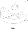
- FIG. 4 shows exemplary components of a LiDAR sensor 20, in accordance with one or more embodiments of the disclosure.
- a LiDAR sensor 20 direct a light source 29 across the LFOV 22 with a scanner 30.
- the light source 29 may be a monochromatic or broad-spectrum light source.
- the light source 29 may be a laser light source.
- the light source 29 may provide visible light, near infrared (NIR) light, mid-infrared (MIR) light, far infrared (FIR) light, ultraviolet (UV) light, light from other portions of the electromagnetic spectrum, or combinations thereof.
- NIR near infrared
- MIR mid-infrared
- FIR far infrared
- UV ultraviolet
- the scanner 30 includes a mirror or prism that alters a direction of the light from the light source 29.
- the scanner 30 may rotate through a full 360° rotation (e.g., in the scanning direction 27) while the light is emitted from the LiDAR sensor 20 (e.g., not occluded by another portion of the LiDAR sensor 20) in the LFOV 22.
- the scanner 30 oscillates to emit the light in the LFOV 22.
- the scanner 30 may include a first mirror that oscillates in a first direction (e.g., in the direction of the lateral width of the LFOV 25) and a second mirror that oscillates in a second direction at least partially orthogonal to the second direction (e.g., in the direction of the vertical height of the LFOV 26).
- a microelectromechanical system (MEMS) scanner may allow control over the orientation of the mirror(s).
- the scanner 30 may include a dual axis mirror that oscillates in both the first direction and the second direction.
- the scanner 30 includes a phased array of light sources 29 that further allows for scanning and/or replaces the rotating or oscillating scanner 30.
- the LiDAR sensor 20 may further include a photodetector 31 configured to detect the light from the light source 29 that is scattered by objects in the environment back to the LiDAR sensor 20.
- the photodetector 31 includes a photodiode or photomultiplier.
- the photodetector 31 may be an active sensor integrated with the light source 29.
- the photodetector 31 is separate from the light source 29 and the backscattered light is received through a hole or beam splitter of the scanner 30.
- FIG. 5 shows exemplary components of a camera 19, such as, for example, the camera 19 described in relation to the image collection unit described in relation to FIG. 3 , in accordance with one or more embodiments of the disclosure.
- the camera 19 includes at least one optical lens 32, an optional filter 33, a camera sensor 34, and a processing circuitry 35.
- the optical lens 32 may collect and direct light from the CFOV 21 of the camera 19 through the filter 33 to the detector and serve to focus and/or magnify images.
- the at least one optical lens 32 may be of the type of a fisheye lens, an f-theta lens, a rectilinear lens, or any other standard and moderate wide-angle lens.
- a standard lens is typically defined as a lens with a focal length being approximately equal to the diagonal of the camera sensor 34. This results in a CFOV 21 that may be similar to what human eyes see.
- Moderate wide-angle lenses have shorter focal lengths than standard lenses, typically ranging from 24 mm to 35 mm for full-frame cameras. These lenses offer a wider CFOV 21 than standard lenses and can capture more of the scene in the frame.
- the optical lens 32 includes an f-theta lens, which may facilitate outputting an angle value for each pixel of the image data, the angle value corresponding to a corresponding angle in the LFOV 22 of the LiDAR sensor 20.
- the optional filter 33 passes selected spectral bands such as ultraviolet, infrared, or other bands to the camera sensor 34 while filtering out other spectral bands.
- the camera sensor 34 may be a digital image sensor that converts electromagnetic energy to an electric signal and employs image sensing technology such as charge-coupled device (CCD) technology and/or complementary metal oxide semiconductor (CMOS) technology.
- CCD charge-coupled device
- CMOS complementary metal oxide semiconductor
- the camera sensor 34 may be configured to detect a narrow range of wavelengths (e.g., a monochromatic camera sensor) of light, a broad range of wavelengths (e.g., a broad-spectrum camera sensor) or a plurality of ranges of wavelengths of light (e.g., a multi-spectrum camera sensor).
- the camera sensor 34 may detect visible light, near infrared (NIR) light, mid-infrared (MIR) light, far infrared (FIR) light, ultraviolet (UV) light, light from other portions of the electromagnetic spectrum, or combinations thereof.
- the processing circuitry 35 may include a circuitry for amplifying and processing the electric signal generated by the camera sensor 34 to generate image data, which is passed to the one or more computing devices such as the imaging controller 3.
- the image data captured by the camera 19 may contain at least a part of the vehicle 1.
- FIG. 6 shows a flowchart 36 representation of a method of controlling an agricultural vehicle, in accordance with one or more embodiments of the disclosure.
- an imaging system 5 (such as described in relation to FIG. 1 ) includes a camera sensor 34 (such as in a camera 19) and a LiDAR sensor 20.
- the camera sensor 34 collects image data 37 that is transmitted from the imaging system 5 to an imaging controller 3.
- the LiDAR sensor 20 (such as described in relation to FIG. 4 ) collects LiDAR data 38 that is transmitted to the imaging controller 3.
- the image data 37 includes a plurality of pixels having X- and Y-coordinates relative to the CFOV 21.
- the image data 37 includes a greyscale intensity value at each of the pixels.
- the image data 37 includes a color value at each of the pixels. In some embodiments, the image data 37 includes a timestamp. In some embodiments, pixels of the image data 37 individually include one or more of color image data (e.g., in the RGB color space), multispectral image data, SWIR data, LWIR data, NIR data, and/or timestamp data.
- the LiDAR data 38 is, in some embodiments, a point cloud (e.g., a LiDAR point cloud, such as a 3D LiDAR point cloud) with angular values and depth values for each point (e.g., voxel).
- each of the points in the point cloud includes angular values such as an azimuthal angle and an elevation angle relative to the scanner 30 ( FIG. 4 ) to designate the projection location of the point in the point cloud.
- the LiDAR data 38 further includes a depth value for each of the points in the point cloud corresponding to the depth of the object scattering the light from the light source back to the LiDAR sensor 20 (e.g., the distance of the object from the LiDAR sensor 20).
- the image data 37 includes a full image of the CFOV 21 of the camera sensor 34.
- the image data 37 includes image data for the entire CFOV 21.
- the image data 37 is less than the entire CFOV 21.
- the image data 37 transmitted to the imaging controller 3 may include only a portion of the CFOV 21 (corresponding to a portion of the CFOV 21 captured when the LiDAR sensor 20 is scanning a corresponding portion of the LFOV 22), as will be described in more detail in relation to FIG. 8 .
- the image data 37 is interpolated to correspond to the frequency of the LiDAR data 38.
- the image data 37 may be interpolated using one or more advanced interpolation techniques, such as optical flow methods (e.g., the Lucas-Kanade method or Gunnar-Farneback) for computer vision, Kalman filtering, or deep neural network-based (DNN-based) trackers.
- optical flow methods e.g., the Lucas-Kanade method or Gunnar-Farneback
- DNN-based deep neural network-based
- the method of controlling the agricultural vehicle further includes, in some examples, performing an image segmentation operation of the image data 37 using an image recognition manager 39 to generate segmented image data 39-1.
- Segmenting the image data 37 may include performing one or more of semantic segmentation, instance segmentation, panoptic segmentation, or other object recognition and identification techniques on the image data 37.
- the method optionally includes performing a LiDAR segmentation operation on the LiDAR data 38 using a LiDAR recognition manager 40 to generate segmented LiDAR data 40 -1.
- the three-dimensional point cloud of the LiDAR data 38 may be converted to a two-dimensional space, and the two-dimensional LiDAR image may be segmented according to one or more object recognition and identification techniques, such as semantic segmentation, instance segmentation, and panoptic segmentation.
- object recognition and/or identification includes using a YOLO (You only look once) method or similar algorithm.
- the LiDAR recognition manager 40 is configured to perform a LiDAR segmentation operation on the 3D LiDAR data 38 using, for example, a LiDAR segmentation neural network trained with a 3D LiDAR point cloud dataset including agricultural objects.
- the LiDAR segmentation neural network may be configured to perform a 3D segmentation operation, such as using a deep neural network.
- segmenting the image data 37 and/or the LiDAR data 38 includes providing the image data 37 and/or the LiDAR data 38 to the respective one of the image recognition manager 39 and the LiDAR recognition manager 40.
- the image recognition manager 39 and the LiDAR recognition manager 40 individually include a trained neural network, each of which may be different than one another.
- identification of a known object allows for a reduction in computational and/or storage resources.
- identification of a trailer of known make and model allows the imaging controller 3 to access the dimensions of the trailer from a storage device (e.g., storage device 16 ( FIG.2 )) including dimensions that may not be visible (e.g., non-visible dimensions) from the perspective of the imaging system 5.
- a point cloud (e.g., the point cloud of the LiDAR data 38) may be refined by fitting the known dimensions of a known object to the point cloud, which may be beneficial in instances where the LiDAR data 38 includes noise (e.g., one or more objects are at least partially obstructed from the LFOV 22).
- the non-visible dimensions may be mapped to the LiDAR data 38, the segmented LiDAR data 40-1, and/or to fused data (e.g., fused data 41-1) to provide the imaging controller 3 and/or vehicle controller 42 with information regarding unimaged portions of the known object for navigation purposes.
- Some agricultural vehicles are capable of very tight- or zero-radius turns, and identification of a known object and fitting of known dimensions to the known object in the LiDAR data 38, the segmented LiDAR data 40-1, and/or the fused data 41-1 may facilitate awareness of a side or rear of the known object before the imaging system 5 has line-of-sight to that portion of the object, enabling the vehicle to navigate around the known object.
- the trained neural network used for the object recognition and/or the segmentation of each of the image recognition manager 39 and the LiDAR recognition manger 40 is selected from a plurality of agriculturally trained neural networks.
- the neural networks of the plurality of neural networks include the same model trained on different training agricultural datasets, such as a different training dataset related to different locations (climates, latitudes, elevations, etc.), different agricultural tasks (bailing, tilling, harvesting, etc.), different seasons (Spring, Summer, Fall, Winter), etc.
- the trained neural network is selected based on an initial input from an operator of the imaging system 5 and/or the vehicle 1.
- the initial input is received by an operator at the imaging controller 3 and may include an identification of an agricultural task to be performed and/or a location (e.g., a particular field) where the agricultural task will be performed.
- the initial input is received from the imaging system 5 during a startup sequence.
- the imaging system 5 may identify one or more objects in image data 37 and/or LiDAR data 38 and use the results of the one or more objects as an input to select the trained neural network or each of the image recognition manager 39 and the LiDAR recognition manger 40.
- the method further includes fusing at least a portion of the image data 37 and the LiDAR data 38 using a data fusion manager 41 to generate fused data 41-1.
- fusing the image data 37 and the LiDAR data 38 includes fusing a segmented instance of the image data 37 with the LiDAR data 38.
- fusing the image data 37 and the LiDAR data 38 includes fusing a segmented instance of the LiDAR data 38 with the image data 37.
- fusing the image data 37 and the LiDAR data 38 includes fusing the segmented image data from the image recognition manager 39 and the segmented LiDAR data from the LiDAR recognition manager 40 using the data fusion manager 41.
- the fusing may include aligning the image data 37 and LiDAR data 38 (or the segmented image data 39-1 with the segmented LiDAR data 40-1).
- aligning the image data 37 and the LiDAR data 38 may include determining the presence at least one edge in the LiDAR data 38 and the image data 37 to align the edges of a similar object or feature in the data.
- aligning the image data 37 and the LiDAR data 38 includes aligning at least one boundary of the frame of the image data 37 and the LiDAR data 38.
- the CFOV 21 and LFOV 22 are substantially the same, allowing the alignment of the image data 37 and the LiDAR data 38 by alignment of the boundary of the pixels of the image data 37 with the points of the LiDAR data 38.
- aligning the image data 37 and the LiDAR data 38 includes determining a relative angular position of the image data 37 with respect to the LiDAR data 38 based on the relative angular position of the camera 19 (or camera sensor 34) to the LiDAR sensor 20. For example, when a center point of the CFOV 21 and a center point of the LFOV 22 are aligned, the image data 37 and the LiDAR data 38 may be substantially aligned. In some embodiments, aligning the image data 37 and the LiDAR data 38 includes determining a relative angular value of the LiDAR data 38 with respect to the image data 37.
- a pixel in the LiDAR data 38 may have an angular value (e.g., 5° in the scan direction 27).
- the angular value may be the relative angular value.
- the angular value of the LiDAR data 38 may be changed by an offset between the camera 19 and the LiDAR sensor 20. Adding the offset to the angular value(s) of the LiDAR data 38 produces the relative angular value of the LiDAR data 38 relative to the image data 37.
- determining a relative angular position of the image data 37 with respect to the LiDAR data 38 includes determining a position of the pixels of the image data 37 relative to the angular values of the LiDAR data 38.
- the image data 37 is compiled from a plurality of individual camera frames and/or portions of the frames, as will be described in more detail in relation to FIG. 8 .
- fusing the image data 37 and the LiDAR data 38 includes projecting the image data 37 onto the point cloud of the LiDAR data 38.
- fusing the image data 37 and the LiDAR data 38 with the fusion manager 41 includes projecting the point cloud of the LiDAR data 38 onto the two-dimensional image data 37. Pixelwise fusion of the image data 37 and the LiDAR data 38 allows mapping of depth information to the image data 37 for high confidence identification and positioning of the objects in the fused data 41-1 that is transmitted to the vehicle controller 42.
- the image recognition manager 39 and/or the LiDAR recognition manager 40 perform other object recognition techniques on the image data 37 and/or LiDAR data 38, respectively.
- the image recognition manager 39 and/or the LiDAR recognition manager 40 may perform object detection on the image data 37 and/or LiDAR data 38, placing a bounding box on the detected object in the data.
- the fusion manager 41 produces the fused data 41-1 including the bounded area of the fused data 41-1 based at least partially on the object detection.
- the fused data 41-1 is further segmented based at least partially on the bounded area.
- the fused data 41-1 is segmented using an object segmentation operation, such as an instance segmentation operation.
- the object segmentation operation may be performed with an object segmentation manager trained with an agricultural dataset including image data and LiDAR data.
- the vehicle controller 42 is in data communication with the propulsion system 6 and the steering system 7.
- the vehicle controller 42 may be, optionally, in data communication with the agricultural tool 8 or implement.
- the vehicle controller 42 receives the fused data 41-1 including at least one fused instance (e.g., an instance of an agricultural object in the fused data 41-1) from the imaging controller 3 and determines at least one navigational command based on the fused data 41-1.
- the vehicle controller 42 transmits navigational commands to the propulsion system 6 to modify or set a speed of the vehicle 1 and to the steering system 7 to change a direction of the vehicle 1.
- the vehicle controller 42 may further transmit tool or implement commands to the agricultural tool 8 or implement to operate at least one part of the agricultural tool 8 or implement based on the fused data 41-1.
- the vehicle controller 42 navigates the vehicle 1 to avoid an identified object, such as a human, and, in other examples, the vehicle controller 42 navigates the vehicle 1 toward an identified object, such as a bale of hay.
- the imaging controller 3 creates and provides at least one fused instance in the fused data 41-1 to the vehicle controller 42.
- FIG. 6 illustrates the imaging system 5 and the imaging controller 3 as being coupled to the vehicle 1, the disclosure is not so limited. In other embodiments, the imaging system 5 and the imaging controller 3 are located remotely to the vehicle 1 and are configured to transmit the fused data 41-1 to the vehicle controller 42.
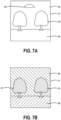
- FIG. 7A through 7C illustrates different types of image segmentation of the image data 37 and/or fused data 41-1. While segmentation of the image data 37 is described in relation to FIG. 7A through 7C , it should be understood that similar segmentation may be performed on the LiDAR data 38.
- FIG. 7A illustrates image data 37 including trees 43 (such as apple trees in an orchard), grass 44, open sky 45, and a cloud 46 in the sky 45.
- the image segmentation may segment the portions of the image data 37 into segments, which are assigned tags or other metadata categorizations to classify each pixel of the image data 37.
- FIG. 7B illustrates an example of a semantic segmentation operation.
- Semantic segmentation segments the image data 37 by placing each pixel into a category based on the object defined by the pixel in the image data 37. For example, every pixel of the image data 37 is categorized as one of "trees" 47, "grass” 48, and "sky” 49 in the example of semantic segmentation in FIG. 7B .
- semantic segmentation provides boundaries between objects or regions of the image data 37 that can be beneficial in alignment of the image data with the spatial boundaries of the LiDAR data 38.
- the imaging controller 3 does not segment all pixels of the image data 37, reducing computational resource and storage requirements for the image data and, later, fused data. For example, in some embodiments, the imaging controller 3 segments only agricultural objects in the image data 37, ignoring background pixels in the image data 37, such as pixels defining the sky 49, the cloud 46, and the grass 48.
- FIG. 7C illustrates an example of an instance segmentation operation.
- Instance segmentation provides discrete instances of objects in the same category, such as a first tree instance 47-1 and a second tree instance 47-2.
- the agriculturally-trained neural network(s) described in relation to FIG. 6 provides precise identification and segmentation of objects of the image data 37.
- an agriculturally-trained neural network(s) may segment and identify species of trees, ripeness of crops, different makes or models of agricultural vehicles, tools, and implements, and other agricultural-specific categories of objects that provides more efficient imaging, processing, navigation, and operation of the imaging system and vehicle.
- a LiDAR sensor 20 may have a scanning direction 27 across the LFOV 22.
- Many LiDAR sensors have a scan rate (e.g., capture rate) that is less than the exposure time of a camera sensor, which may cause differences in the object position and/or shape within the CFOV 21 and the LFOV 22 when imaged with each of the camera sensor 34 and the LiDAR sensor 20, respectively.
- the scanning direction 27 can cause a distortion of the object's position or shape in the LiDAR data 38.
- the LiDAR sensor 20 may scan across the LFOV 22 in 50 milliseconds (ms), while the camera sensor 34 may be exposed with a global shutter for 2 ms.
- the camera sensor 34 may capture 25 frames of image data 37 during one scan of the LiDAR sensor 20 and the objects in the LiDAR data 38 may move for a duration of up to 25 times as long as objects in each frame of image data 37.
- the imaging system 5 and/or imaging controller 3 may use a plurality of image data frames to approximate the scanning direction and/or the scan rate of the LiDAR sensor 20 to better align the image data 37 with the LiDAR data 38, as illustrated in FIG. 8 .
- the higher capture rate of the camera 19 and/or camera sensor 34 may allow the image data 37 to include subregions of the CFOV 21 (corresponding to subregions of the LFOV 22) captured at different times within the capture time of a scan of the LiDAR data 38.
- each portion of the CFOV 21 is captured substantially simultaneously with the angular position of the scanner 30 of the LiDAR sensor 20 and a corresponding LFOV 22.
- each frame of image data 37 may be captured substantially simultaneously with the LiDAR data 38 such that the image data 37 in each frame corresponds to a corresponding portion of the LFOV 22.
- each frame of the image data 37 may include less than the entire CFOV 21 and may include pixels corresponding to a portion of the LFOV 22.
- FIG. 8 illustrates an example of collecting or selecting image data 37 including a plurality of slices of a CFOV 22 overlaid on LiDAR data 38, according to one or more embodiments of the disclosure.
- the image data 37 includes portions 50-1, 50-2, 50-3 that each have a lateral position relative to (e.g., within) the CFOV 22.
- the portions 50-1, 50-2, 50-3 of the image data 37 may be positioned at equal lateral intervals relative to a centerline 52 of the lateral width of the LiDAR data 38 and of the CFOV 22.
- the centerline 52 may be an azimuthal position of 0 degrees of the angular position of the scanner 30 and/or angular value 51-1, 51-2, 52-3 of the LiDAR data 38.
- the LiDAR sensor 20 and/or LiDAR data 38 has a scanning direction 27 at least in the lateral direction, and the portions 50-1, 50-2, 50-3 of the image data 37 can substantially match the angular position of the scanner 30 and/or relative angular value 51-1, 51-2, 52-3 of the LiDAR data 38.
- an area of each of the portions 50-1, 50-2, 50-3 of the image data 37 is constant across the image data 37. In other words, each of the portions 50-1, 50-1, 50-3 includes substantially the same area. In other embodiments, an area of the portions 50-1, 50-2, 50-3 of the image data 37 changes across the lateral width of the image data 37, CFOV 22, or LiDAR data 38 such that at least one of the portions 50-1, 50-2, 50-3 has a different area than at least another of the portions 50-1, 50-2, 50-3.
- a first portion 50-1 of the image data 37 corresponding to a first relative angular value 51-1 of the LiDAR data 38 has a greater area than a third portion 50-3 of the image data 37 corresponding to a third relative angular value 51-3 of the LiDAR data 38.
- a first portion 50-1 of the image data 37 corresponding to a first angular value 51-1 of the LiDAR data 38 has a lesser area than a third portion 50-3 of the image data 37 corresponding to a third angular value 51-3 of the LiDAR data 38.
- the portions 50-1, 50-2, 50-3 of the image data 37 may be collected or selected by a variety of techniques.
- the camera sensor captures an entire frame of image data 37 multiple times within a single scan of the LiDAR data 38.
- Each portion 50-1, 50-2, 50-3 is selected from a different frame at a time interval within the scan duration of the LiDAR data 38 corresponding to the time when the LiDAR sensor 20 is capturing LiDAR data 38 with a corresponding angular value 51-1, 51-2, 51-3 as the portion 50-1, 50-2, 50-3 of the image data 37.
- the LiDAR data 38 may be collected over 50 ms, while 25 frames of image data are captured at the same time, allowing the image data 37 to be compiled from 25 portions, each portion corresponding to one of the 25 frames. At least a portion of the compiled image data 37 including the selected portion is then aligned with and/or fused to the LiDAR data 38 for controlling the agricultural vehicle 1.
- the camera only exposes pixels of a region of the photoreceptor array of the camera sensor 34 that corresponds to the portion 50-1, 50-2, 50-3 of the CFOV 22, and the camera reads out the image data 37 for the camera sensor 34.
- Such image data may assist in alignment of the exposed portions when compiling the image data 37.
- the camera may generate image data in each of the portions 50-1, 50-2, 50-3 at times corresponding to the time when the LiDAR sensor 20 is scanning and obtaining LiDAR data 38 from the corresponding angular value 51-1, 51-2, 52-3 of the LiDAR data 38.
- the frame rate of the camera may more closely approximate the scan rate of the LiDAR sensor 20.
- the camera 19 may expose the entire array of the camera sensor 34, and subsequently only read out the image data 37 from a selected region of the camera sensor 34 corresponding to the portion 50-1, 50-2, 50-3 of the CFOV 22.
- the readout time of the camera sensor is longer than the exposure time. Reducing the size of the region that is read out after the exposure may allow an increase in the frame rate of the camera 19, providing more portions 50-1, 50-2, 50-3 of the CFOV 22 to better approximate the LiDAR scanning direction 27 and the scan rate of the LiDAR sensor 20.
- a lens of the camera may move to change a CFOV 22 in the scanning direction 27, allowing replication of the scanning direction 27 without altering the behavior of the camera sensor 34.
- the alignment and projection of the image data 37 and the LiDAR data 38 can be more precise and more robust than embodiments in which the image data 37 is not angularly matched with the LiDAR data 38.
- FIG. 9 shows an exemplary system for spatial mapping of an environment 53 for controlling an agricultural vehicle 1 including an imaging system 5, according to one or more embodiments of the present disclosure.
- the agricultural vehicle 1 operates within a known environment 53 or bounded geographic region.
- many agricultural vehicles 1 operate within a repeated known environment 53 in which the recording and/or mapping of detected and identified objects 12 and obstacles (such as trees 43) relative to the vehicle 1 in the environment 53 improves safety and efficiency for future agricultural operations.
- the location of the vehicle 1 and/or imaging system 5 relative to the environment 53 may be tracked, such as by global positioning satellite (GPS) transceiver and/or by one or more local ranging systems, such as radar or LiDAR ranging from known survey locations.
- GPS global positioning satellite
- the imaging system 5 is oriented in a fixed direction relative to the direction of travel of the vehicle 1, and only portions of the environment 53 are visible at a time.
- the imaging system 5 moves and images different obstacles and objects 12 in the environment 53.
- the imaging system 5 can determine a distance of the obstacles and objects 12 from the vehicle 1 in the environment 53 while imaging and identifying the obstacles and objects 12 in the environment 53.
- the depth information collected in the LiDAR data is different from a distance from the measured location of the vehicle 1.
- the imaging system 5 may have an offset value based on the position of the imaging system 5 and/or LiDAR sensor 20 relative to the GPS transceiver or other device that measures the position of the vehicle 1 in the environment 53 and the imaging controller 3 may compensate for such offset.
- a LiDAR sensor 20 that is 1 meter forward of the GPS transceiver may measure depth information to an object 12 that is 1 meter less than a distance from the GPS transceiver to the object 12.
- the position and orientation of the vehicle 1 and the field of view of the imaging system 5 relative to the environment 53 is used to determine the position and/or orientation of the static obstacles and objects 12 identified in the environment 53, which may be used in future agricultural operations.
- the imaging system 5 may record the location and other details (e.g., size, color, orientation) of the object 12 to a storage device (such as the storage device 16 described in relation to FIG. 2 ).
- the recorded object 12 and location of the object 12 may be later accessed by the imaging system 5 when the vehicle 1 is performing operations in the environment 53 to reduce imaging resource demands, improve imaging accuracy, refine the neural network used in the identification or segmentation, measure changes (e.g., growth) in the objects between operations, or combinations thereof.
- the vehicle 1 and imaging system 5 image and identify a moving object 54 in the environment 53.
- the imaging system 5 measures a position and velocity of the moving object 54 in the environment 53.
- the imaging system 5 may record the location and velocity of the moving object 54 to a storage device (such as the storage device 16 described in relation to FIG. 2 ).
- the recorded moving object 54 and location and velocity of the moving object 54 may be later accessed by the imaging system 5 when the vehicle 1 is performing operations in the environment 53 to calculate a predicted or expected location of the moving object 54 at a later time.
- Calculating a predicted or expected location of the moving object 54 may reduce imaging resource demands, improve imaging accuracy, refine the neural network used in the identification or segmentation, measure changes (e.g., growth) in the objects between operations, or combinations thereof.
- the imaging system 5 may predict that a moving object 54 will cross the environment 53 before the vehicle 1 changes orientation and the imaging system 5 can image the moving object 54 again.
- the imaging system 5 may be able to identity the moving object 54 with greater accuracy even from a far distance when the distant predicted location of the moving object 54 is calculated.
- the moving object 54 may move behind a tree 43 or other object that occludes at least a portion of the moving object 54 from the imaging system 5. Recording and predicting the location and velocity of a moving object 54 may improve safety during agricultural operations, such as by providing details for the moving object 54 when at least a portion of the moving object 54 is occluded from a field of view of the imaging system 5.
- FIG. 10 is a simplified flow chart illustrating a method 60 of operating an agricultural machine, in accordance with one or more embodiments of the disclosure.
- the method 60 includes receiving a user input indicative of an agricultural operation to be performed, as shown in act 61.
- the agricultural operation may include, for example, one or more of a baling, planting, spraying, spreading, harvesting, cutting, swathing, tilling operation.
- the method 60 may include identifying one or more types of objects that may be present (e.g., proximate the vehicle) based on the selected agricultural operation, as shown in act 62.
- act 62 may include determining that objects that may be encountered include a planter (e.g., a towed implement including row units), a tractor, associations between objects (e.g., between a towed implement and the tractor), static objects (e.g., rocks, boulders, utility poles, windmills), animals, and humans.
- each agricultural operation may include a unique list of objects that may be detected and may include a unique neural network trained with a unique set of agricultural data.
- the method 60 may further include capturing image data via a camera (e.g., cameras 19 ( FIG. 3 )), as shown in act 63.
- Capturing the image data may include capturing the image data while operating (e.g., driving) the vehicle.
- the image data may include one or more of RGB image data, SWIR data, NIR data, and LWIR data.
- the image data may also include a timestamp.
- the pixels of the image data include coordinate information.
- the method 60 may further include capturing LiDAR data with a LiDAR sensor (e.g., LiDAR sensor 20 ( FIG. 3 )), as shown in act 64.
- Capturing the LiDAR data may include capturing the LiDAR data while operating (e.g., driving) the vehicle.
- the method 60 includes analyzing the image data to generate segmented image data (e.g., segmented image data 39-1 ( FIG. 6 )), as shown in act 65.
- Analyzing the image data may include labeling objects identified in the image data.
- analyzing the image data may include analyzing the image data with one or more neural networks (e.g., one or more deep neural networks) trained with agricultural data specific to an agricultural environment. The neural network may be selected during act 62, as described above.
- analyzing the image data may include performing an object segmentation operation (e.g., an instance segmentation operation) on the image data, as described above with reference to FIG. 6 .
- an object segmentation operation e.g., an instance segmentation operation
- the method 60 may further include analyzing the LiDAR data to generated segmented LiDAR data (e.g., segmented LiDAR data 40-1 ( FIG. 6 )), as shown in act 66.
- the LiDAR data may be processed with, for example, an agricultural object detection neural network, as described above with reference to FIG. 6 , to generate the segmented LiDAR data.
- the method 60 includes fusing the segmented image data and the segmented LiDAR data, as shown in act 67.
- Fusing the segmented image data with the segmented LiDAR data may include performing one or more fusion operations on the segmented image data and the segmented LiDAR data, as described above with reference to the fusion manager 41 ( FIG. 6 ).
- the method 60 may further include performing one or more navigation operations based on the fused data, as shown at act 68.
- the one or more navigation operations may include controlling one or more of a propulsion system of the vehicle, the braking system of the vehicle, the steering of the vehicle, and a route of the vehicle.
- act 68 may include reducing a speed of the vehicle below a threshold (e.g., below about 8 kilometers per hour (about 5 miles per hour)).
- act 68 may include stopping the vehicle until the human has moved out of the path of the vehicle.
- imaging systems, devices, and methods described herein may reduce computational resources and improve accuracy and precision of object identification during agricultural operations.
- the imaging systems, devices, and methods described herein may provide more accuracy alignment of image data and LiDAR data during or after collection that provides more precise measurements with less computational demand.
Landscapes
- Engineering & Computer Science (AREA)
- Physics & Mathematics (AREA)
- General Physics & Mathematics (AREA)
- Theoretical Computer Science (AREA)
- Radar, Positioning & Navigation (AREA)
- Remote Sensing (AREA)
- Multimedia (AREA)
- Computer Vision & Pattern Recognition (AREA)
- Life Sciences & Earth Sciences (AREA)
- Evolutionary Computation (AREA)
- General Health & Medical Sciences (AREA)
- Health & Medical Sciences (AREA)
- Aviation & Aerospace Engineering (AREA)
- Automation & Control Theory (AREA)
- Computer Networks & Wireless Communication (AREA)
- Electromagnetism (AREA)
- Medical Informatics (AREA)
- Software Systems (AREA)
- Databases & Information Systems (AREA)
- Computing Systems (AREA)
- Artificial Intelligence (AREA)
- Environmental Sciences (AREA)
- Soil Sciences (AREA)
- Mechanical Engineering (AREA)
- Vascular Medicine (AREA)
- Traffic Control Systems (AREA)
Applications Claiming Priority (1)
| Application Number | Priority Date | Filing Date | Title |
|---|---|---|---|
| GBGB2318254.6A GB202318254D0 (en) | 2023-11-29 | 2023-11-29 | Agricultural vehicles including an imaging controller, and related methods |
Publications (1)
| Publication Number | Publication Date |
|---|---|
| EP4562989A1 true EP4562989A1 (fr) | 2025-06-04 |
Family
ID=89429033
Family Applications (1)
| Application Number | Title | Priority Date | Filing Date |
|---|---|---|---|
| EP24207407.8A Pending EP4562989A1 (fr) | 2023-11-29 | 2024-10-18 | Véhicule agricole à fonctionnement et sécurité améliorés, et procédés associés |
Country Status (3)
| Country | Link |
|---|---|
| US (1) | US20250174029A1 (fr) |
| EP (1) | EP4562989A1 (fr) |
| GB (1) | GB202318254D0 (fr) |
Citations (3)
| Publication number | Priority date | Publication date | Assignee | Title |
|---|---|---|---|---|
| US20220012916A1 (en) * | 2019-05-09 | 2022-01-13 | Zoox, Inc. | Image-based depth data and localization |
| US20220066456A1 (en) * | 2016-02-29 | 2022-03-03 | AI Incorporated | Obstacle recognition method for autonomous robots |
| US20220394156A1 (en) * | 2018-09-26 | 2022-12-08 | Zoox, Inc. | Image scan line timestamping |
Family Cites Families (11)
| Publication number | Priority date | Publication date | Assignee | Title |
|---|---|---|---|---|
| US10229341B2 (en) * | 2016-12-21 | 2019-03-12 | Volkswagen Ag | Vector engine and methodologies using digital neuromorphic (NM) data |
| EP3438776B1 (fr) * | 2017-08-04 | 2022-09-07 | Bayerische Motoren Werke Aktiengesellschaft | Procédé, appareil et programme informatique pour véhicule |
| WO2019113749A1 (fr) * | 2017-12-11 | 2019-06-20 | Beijing Didi Infinity Technology And Development Co., Ltd. | Systèmes et procédés d'identification et de localisation d'objets autour d'un véhicule |
| GB2606740A (en) * | 2021-05-19 | 2022-11-23 | Agco Int Gmbh | Residue monitoring |
| JP7746712B2 (ja) * | 2021-07-09 | 2025-10-01 | 株式会社デンソー | 車両用装置および車両制御方法 |
| GB202114576D0 (en) * | 2021-10-12 | 2021-11-24 | Agco Int Gmbh | Harvester systems and methods for automated and semi-automated filling of groups of receiving vehicles |
| GB202114575D0 (en) * | 2021-10-12 | 2021-11-24 | Agco Int Gmbh | Harvester systems and methods for automated and semi-automated filling of bins of receiving vehicles |
| US12360247B1 (en) * | 2022-04-29 | 2025-07-15 | Zoox, Inc. | Partial sensor data processing for latency reduction |
| US12581054B2 (en) * | 2022-05-27 | 2026-03-17 | Motional Ad Llc | Image based LiDAR-camera synchronization |
| EP4384848B1 (fr) * | 2022-10-31 | 2025-12-03 | Google Technology Holdings LLC | Système de capture d'image comprenant un dispositif lidar et des caméras comportant un capteur d'obturateur roulant |
| US12475597B2 (en) * | 2023-03-14 | 2025-11-18 | GM Global Technology Operations LLC | Robust lidar-to-camera sensor alignment |
-
2023
- 2023-11-29 GB GBGB2318254.6A patent/GB202318254D0/en not_active Ceased
-
2024
- 2024-10-18 EP EP24207407.8A patent/EP4562989A1/fr active Pending
- 2024-10-21 US US18/922,252 patent/US20250174029A1/en active Pending
Patent Citations (3)
| Publication number | Priority date | Publication date | Assignee | Title |
|---|---|---|---|---|
| US20220066456A1 (en) * | 2016-02-29 | 2022-03-03 | AI Incorporated | Obstacle recognition method for autonomous robots |
| US20220394156A1 (en) * | 2018-09-26 | 2022-12-08 | Zoox, Inc. | Image scan line timestamping |
| US20220012916A1 (en) * | 2019-05-09 | 2022-01-13 | Zoox, Inc. | Image-based depth data and localization |
Also Published As
| Publication number | Publication date |
|---|---|
| US20250174029A1 (en) | 2025-05-29 |
| GB202318254D0 (en) | 2024-01-10 |
Similar Documents
| Publication | Publication Date | Title |
|---|---|---|
| EP4562987A2 (fr) | Véhicules agricoles comprenant un dispositif de controle d'imagerie, et procédés associés | |
| RU2605775C2 (ru) | Система и способ автоматического документирования ситуаций при полевых работах | |
| RU2649916C2 (ru) | Система и способ управления системой автоматического вождения сельскохозяйственного транспортного средства | |
| EP2368419B1 (fr) | Procédé pour détecter une structure dans un champ, procédé de direction d'un véhicule agricole et véhicule agricole | |
| EP4564306A1 (fr) | Véhicules agricoles comprenant un dispositif de commande d'imagerie, et procédés associés | |
| EP3871481B1 (fr) | Véhicule agricole équipé d'un dispositif d'imagerie 3d avant et arrière | |
| CA3199715A1 (fr) | Procede de traitement selectif de vegetation dans un champ | |
| JP7756174B2 (ja) | 地図生成システムおよび地図生成方法 | |
| US20230403964A1 (en) | Method for Estimating a Course of Plant Rows | |
| Feng et al. | Cotton yield estimation based on plant height from UAV-based imagery data | |
| EP4562989A1 (fr) | Véhicule agricole à fonctionnement et sécurité améliorés, et procédés associés | |
| US20250169389A1 (en) | Agricultural Vehicles Including an Imaging Controller, and Related Methods | |
| US20260072442A1 (en) | Agricultural anomaly detection and validation systems, and related systems, methods, and agricultural vehicles | |
| US20260068806A1 (en) | Methods of detecting anomalies associated with agricultural implements, and related agricultural machines | |
| US20260068807A1 (en) | Methods of tracking anomalies in agricultural fields, and related agricultural vehicles | |
| US20260068802A1 (en) | Methods of generating a map of anomalies in agricultural fields, and related agricultural vehicles | |
| US20260068801A1 (en) | Methods of detecting temporal anomalies in agricultural fields, and related agricultural vehicles | |
| US20260072440A1 (en) | Methods of validating anomalies in agricultural fields, and related agricultural vehicles | |
| US20260072441A1 (en) | Methods of classifying anomalies in agricultural fields, and related agricultural vehicles | |
| US20260068804A1 (en) | Methods of detecting anomalies in agricultural fields, and related agricultural vehicles | |
| Fleischmann et al. | Detection of field structures for agricultural vehicle guidance | |
| US20250380633A1 (en) | Objection Detection and Avoidance System, Agricultural Vehicle Include the Objection Detection and Avoidance System, and Related Methods | |
| US20250383667A1 (en) | Objection Detection and Avoidance System, Agricultural Vehicle Include the Objection Detection and Avoidance System, and Related Methods | |
| US20260072443A1 (en) | Methods of detecting anomalies in agricultural fields, and related agricultural vehicles | |
| EP4666824A1 (fr) | Système de guidage, véhicule agricole et procédé associé |
Legal Events
| Date | Code | Title | Description |
|---|---|---|---|
| PUAI | Public reference made under article 153(3) epc to a published international application that has entered the european phase |
Free format text: ORIGINAL CODE: 0009012 |
|
| STAA | Information on the status of an ep patent application or granted ep patent |
Free format text: STATUS: THE APPLICATION HAS BEEN PUBLISHED |
|
| AK | Designated contracting states |
Kind code of ref document: A1 Designated state(s): AL AT BE BG CH CY CZ DE DK EE ES FI FR GB GR HR HU IE IS IT LI LT LU LV MC ME MK MT NL NO PL PT RO RS SE SI SK SM TR |
|
| STAA | Information on the status of an ep patent application or granted ep patent |
Free format text: STATUS: REQUEST FOR EXAMINATION WAS MADE |
|
| 17P | Request for examination filed |
Effective date: 20251204 |