EP4563076A1 - Timbre portable pour collecter des données liées à la santé, et procédé de collecte de données synchronisées avec ledit timbre - Google Patents
Timbre portable pour collecter des données liées à la santé, et procédé de collecte de données synchronisées avec ledit timbre Download PDFInfo
- Publication number
- EP4563076A1 EP4563076A1 EP23212779.5A EP23212779A EP4563076A1 EP 4563076 A1 EP4563076 A1 EP 4563076A1 EP 23212779 A EP23212779 A EP 23212779A EP 4563076 A1 EP4563076 A1 EP 4563076A1
- Authority
- EP
- European Patent Office
- Prior art keywords
- patch
- sensor
- ppg
- ecg
- data
- Prior art date
- Legal status (The legal status is an assumption and is not a legal conclusion. Google has not performed a legal analysis and makes no representation as to the accuracy of the status listed.)
- Pending
Links
Images



Classifications
-
- A—HUMAN NECESSITIES
- A61—MEDICAL OR VETERINARY SCIENCE; HYGIENE
- A61B—DIAGNOSIS; SURGERY; IDENTIFICATION
- A61B5/00—Measuring for diagnostic purposes; Identification of persons
- A61B5/02—Detecting, measuring or recording for evaluating the cardiovascular system, e.g. pulse, heart rate, blood pressure or blood flow
- A61B5/024—Measuring pulse rate or heart rate
- A61B5/02416—Measuring pulse rate or heart rate using photoplethysmograph signals, e.g. generated by infrared radiation
-
- A—HUMAN NECESSITIES
- A61—MEDICAL OR VETERINARY SCIENCE; HYGIENE
- A61B—DIAGNOSIS; SURGERY; IDENTIFICATION
- A61B5/00—Measuring for diagnostic purposes; Identification of persons
- A61B5/0002—Remote monitoring of patients using telemetry, e.g. transmission of vital signals via a communication network
- A61B5/0004—Remote monitoring of patients using telemetry, e.g. transmission of vital signals via a communication network characterised by the type of physiological signal transmitted
- A61B5/0006—ECG or EEG signals
-
- A—HUMAN NECESSITIES
- A61—MEDICAL OR VETERINARY SCIENCE; HYGIENE
- A61B—DIAGNOSIS; SURGERY; IDENTIFICATION
- A61B5/00—Measuring for diagnostic purposes; Identification of persons
- A61B5/02—Detecting, measuring or recording for evaluating the cardiovascular system, e.g. pulse, heart rate, blood pressure or blood flow
- A61B5/021—Measuring pressure in heart or blood vessels
- A61B5/02108—Measuring pressure in heart or blood vessels from analysis of pulse wave characteristics
- A61B5/02125—Measuring pressure in heart or blood vessels from analysis of pulse wave characteristics of pulse wave propagation time
-
- A—HUMAN NECESSITIES
- A61—MEDICAL OR VETERINARY SCIENCE; HYGIENE
- A61B—DIAGNOSIS; SURGERY; IDENTIFICATION
- A61B5/00—Measuring for diagnostic purposes; Identification of persons
- A61B5/02—Detecting, measuring or recording for evaluating the cardiovascular system, e.g. pulse, heart rate, blood pressure or blood flow
- A61B5/024—Measuring pulse rate or heart rate
- A61B5/02438—Measuring pulse rate or heart rate with portable devices, e.g. worn by the patient
-
- A—HUMAN NECESSITIES
- A61—MEDICAL OR VETERINARY SCIENCE; HYGIENE
- A61B—DIAGNOSIS; SURGERY; IDENTIFICATION
- A61B5/00—Measuring for diagnostic purposes; Identification of persons
- A61B5/02—Detecting, measuring or recording for evaluating the cardiovascular system, e.g. pulse, heart rate, blood pressure or blood flow
- A61B5/024—Measuring pulse rate or heart rate
- A61B5/0245—Measuring pulse rate or heart rate by using sensing means generating electric signals, i.e. ECG signals
-
- A—HUMAN NECESSITIES
- A61—MEDICAL OR VETERINARY SCIENCE; HYGIENE
- A61B—DIAGNOSIS; SURGERY; IDENTIFICATION
- A61B5/00—Measuring for diagnostic purposes; Identification of persons
- A61B5/68—Arrangements of detecting, measuring or recording means, e.g. sensors, in relation to patient
- A61B5/6801—Arrangements of detecting, measuring or recording means, e.g. sensors, in relation to patient specially adapted to be attached to or worn on the body surface
- A61B5/683—Means for maintaining contact with the body
- A61B5/6832—Means for maintaining contact with the body using adhesives
- A61B5/6833—Adhesive patches
-
- A—HUMAN NECESSITIES
- A61—MEDICAL OR VETERINARY SCIENCE; HYGIENE
- A61B—DIAGNOSIS; SURGERY; IDENTIFICATION
- A61B5/00—Measuring for diagnostic purposes; Identification of persons
- A61B5/24—Detecting, measuring or recording bioelectric or biomagnetic signals of the body or parts thereof
- A61B5/25—Bioelectric electrodes therefor
-
- A—HUMAN NECESSITIES
- A61—MEDICAL OR VETERINARY SCIENCE; HYGIENE
- A61B—DIAGNOSIS; SURGERY; IDENTIFICATION
- A61B5/00—Measuring for diagnostic purposes; Identification of persons
- A61B5/24—Detecting, measuring or recording bioelectric or biomagnetic signals of the body or parts thereof
- A61B5/316—Modalities, i.e. specific diagnostic methods
- A61B5/318—Heart-related electrical modalities, e.g. electrocardiography [ECG]
- A61B5/346—Analysis of electrocardiograms
- A61B5/349—Detecting specific parameters of the electrocardiograph cycle
-
- A—HUMAN NECESSITIES
- A61—MEDICAL OR VETERINARY SCIENCE; HYGIENE
- A61B—DIAGNOSIS; SURGERY; IDENTIFICATION
- A61B5/00—Measuring for diagnostic purposes; Identification of persons
- A61B5/24—Detecting, measuring or recording bioelectric or biomagnetic signals of the body or parts thereof
- A61B5/316—Modalities, i.e. specific diagnostic methods
- A61B5/318—Heart-related electrical modalities, e.g. electrocardiography [ECG]
- A61B5/346—Analysis of electrocardiograms
- A61B5/349—Detecting specific parameters of the electrocardiograph cycle
- A61B5/352—Detecting R peaks, e.g. for synchronising diagnostic apparatus; Estimating R-R interval
Definitions
- the invention relates to a wearable patch for collecting health-related data. Furthermore, the invention relates to a system comprising a wearable patch for collecting said data. Moreover, the invention relates to a method of fabricating/manufacturing a wearable patch. Also, the invention relates to a method for collecting health-related data using a wearable path.
- ECG electrocardiogram
- PPG photoplethysmogram
- the invention provides for a wearable patch for collecting health-related data, comprising: an electrocardiogram, ECG, sensor; a photoplethysmogram, PPG, sensor; and wherein electrodes of the ECG sensor are arranged on a bottom side of the patch that is attachable to a skin of a user, and wherein an optical window of the PPG sensor is arranged on an opposite side of the patch.
- the wearable patch integrates both an electrocardiogram (ECG) sensor and a photoplethysmogram (PPG) sensor.
- ECG electrocardiogram
- PPG photoplethysmogram
- the electrodes of the ECG sensor are positioned on the bottom side of the patch, ensuring direct contact with the user's skin upon attachment.
- the optical window of the PPG sensor is situated on the patch's opposite side.
- the patch is configured to initiate a measurement on-demand by a placement of a finger on the optical window of the PPG sensor.
- the detection sensor is configured to scan for the presence of a finger.
- the detection sensor is configured to continuously scan for the presence of a finger over the optical window of the PPG sensor and initiate a PPG measurement upon detecting said presence.
- Various detection techniques may be employed.
- the ability to adjust the LED wavelength in real-time, based on the detected skin type, represents a significant advantage.
- This dynamic adaptability ensures that the device can be effectively used for a broad spectrum of users, ensuring consistent and optimal measurement accuracy irrespective of skin type variations.
- Such precision in measurements is critical in health monitoring, as it provides more reliable data.
- Eliminating other synchronization techniques lead to significantly reduced computational needs, which in turn leads to energy savings, a critical factor for wearable medical devices.
- the common device clock can serve the important purpose of ensuring that measurements across the device, from at least the ECG and PPG sensors, are accurately synchronized. By centralizing the reference time point within the same device, data consistency is maintained, eliminating potential discrepancies and enhancing overall measurement reliability.
- the timing of data collection is important.
- ECG and PPG sensors working independently, each with its own clock.
- PAG Pulse Arrival Time
- Such misalignments albeit small, can drastically alter a user's health profile, leading to potential misdiagnoses or incorrect health recommendations.
- the wearable patch ensures that data collected from the ECG sensor and the PPG sensor are anchored to the same temporal reference point. This means that each data point, whether it be an ECG waveform or a PPG waveform, is timestamped in relation to this centralized clock, guaranteeing their temporal alignment.
- the integration of a common device clock in the wearable patch offers an advantage by ensuring consistent and synchronous data collection from both sensors of the wearable patch. This centralization avoids potential time-based discrepancies, thereby significantly enhancing the reliability of the measurements.
- the wearable patch can encompass a shared device clock.
- an external time synchronization unit is used that is configured to perform time synchronization through a wireless connection.
- the wearable patch is configured to synchronize measured signals of ECG and PPG sensors.
- the patch comprises a synchronization module configured to concurrently align and coordinate the data streams from the ECG and PPG sensors. In this way, real-time coherency between the measured signals of both sensors can be ensured.
- the wearable patch may be configured to employ the synchronization module to align and coordinate the data streams from both the ECG and PPG sensors concurrently. This simultaneous coordination ensures that there's real-time coherency between the signals derived from both sensors. By leveraging this module, potential delays or misalignments between the two data streams are effectively mitigated. The result is an enhanced accuracy in health metric derivation, ensuring that the signals from both sensors are harmoniously integrated, thus providing reliable and cohesive health assessments.
- the patch is configured to employ the common device clock for timestamping collected data.
- the wearable patch may utilize the in-built common device clock not only for synchronization but also for the task of timestamping the gathered data, ensuring each data point is chronologically logged.
- Timestamping is the process of associating a specific time or date with a piece of data at the moment of its collection.
- the wearable patch as it collects health-related data such as ECG and PPG readings, the common device clock ensures that every single data point captured is paired with the exact time of its collection.
- the patch ensures the temporal accuracy of the readings. This means that health metrics can be traced back to specific moments in time, which can be important in monitoring certain conditions or events. Furthermore, this timestamping function enhances the reliability of the data. In medical monitoring, especially where continuous data streams are involved, knowing the sequence and exact time of events is important. For instance, understanding the precise temporal relationship between an abnormal ECG reading and a subsequent PPG reading can provide important insights into a patient's cardiovascular health.
- the patch ensures the synchronized collection of data, thereby negating any chances of misinterpretation due to temporal misalignment.
- data collected using the ECG sensor and data collected using the PPG sensor is timestamped and correlated to measure Pulse Arrival Time (PAT).
- PAG Pulse Arrival Time
- the wearable patch offers the capacity to evaluate advanced health parameters, a prime example being the PAT, which is a significant metric, representing the time taken for the pulse wave to travel between two arterial sites, commonly used in cardiovascular health assessments and blood pressure estimation.
- the ECG sensor captures the electrical activity of the heart, marking the initiation of the pulse wave.
- the PPG sensor detects the arrival of this pulse wave by observing changes in blood volume within microvascular tissues.
- data from both these sensors is timestamped using a common device clock, ensuring a synchronized reference for each data point. This uniform timestamping is important in correlating the initiation (from ECG) and arrival (from PPG) of the pulse wave, forming the foundation for precise PAT computation.
- both ECG and PPG sensors can be housed within a singular device. Synchronization challenges often arising due to minor time lags or discrepancies between the clocks of the separate devices, that can adversely impact the accuracy of PAT measurements, can be effectively avoided since both sets of data originate from the same device utilizing a shared clock.
- the ECG sensor is configured to detect electrical activity of the heart and produce an ECG waveform
- the PPG sensor is configured to optically measure blood volume changes in the microvascular bed of tissue and produce a PPG waveform
- the common device clock is operably connected to both said ECG sensor and said PPG sensor, and wherein the common device clock is configured to provide synchronized timestamping for both the ECG waveform and the PPG waveform
- a processing unit of the patch is configured to calculate the PAT based on the synchronized timestamped data from both the ECG and PPG waveforms.
- the ECG sensor can be precisely arranged to capture the heart's electrical activity, producing an ECG waveform in the process.
- the PPG sensor through optical means, can quantify blood volume alterations in the microvascular bed of the tissue, thereby generating a PPG waveform.
- a common device clock being functionally interconnected with both the ECG and PPG sensors, provides synchronized timestamps for the ECG and PPG waveforms.
- a dedicated processing unit in the patch utilizes this synchronized data, subsequently calculating the PAT.
- the shared common device clock can connect to both sensors, facilitating synchronized timestamping for both waveforms.
- a dedicated processing unit in the patch can calculate PAT based on this synchronized data, ensuring measurement cohesion and accuracy.
- the patch's dedicated processing unit can be tasked with the computation of the PAT.
- the processing unit calculates the PAT.
- a processing unit within the patch is tasked with computing the PAT based on the synchronized data from these waveforms.
- the processing unit can be an embedded microcontroller, a FPGA, or even a cloud-based processor, each offering varied levels of computational capabilities.
- the processing unit is further configured to derive PAT as the time difference between a point on the ECG waveform, and a point on the PPG waveform.
- the PAT is computed by determining the temporal difference between a particular point on the electrocardiogram (ECG) waveform and a corresponding point on the photoplethysmogram (PPG) waveform.
- ECG waveform capturing the heart's electrical activity, serves as an initial reference point, marking the heart's contraction and subsequent initiation of a blood pulse.
- PPG waveform resulting from optically measuring blood volume changes in the microvascular bed of tissue, signifies the time the pulse reaches peripheral capillaries.
- the processing unit calculates the PAT.
- This interval is indicative of the time taken for a pulse wave to travel from the heart to the peripheral vasculature, providing invaluable insights into cardiovascular health and arterial stiffness.
- the processing unit in its function, derives the PAT as the time differential between a specific point on the ECG waveform and a corresponding point on the PPG waveform.
- the chosen points may vary, or multiple points may be used to derive an average PAT value.
- a storage module configured to store data
- a wireless communication module is provided that is configured to transmit data to one or more external devices.
- the combination of the storage and wireless communication modules in the wearable patch results in a dual-feature design.
- there's an assurance of secure, in-device data storage which is important for retaining comprehensive health logs over extended periods.
- the ability to transmit this stored data wirelessly ensures that, when needed, the data is effortlessly accessible, be it for immediate health assessments, long-term health trend analysis, or sharing with medical professionals.
- This cohesive integration guarantees that users not only benefit from continuous health tracking but also from the convenience of accessing, analyzing, and sharing their health metrics without any expert.
- the wearable patch further comprises: a battery for powering components of the patch; a recharging mechanism operably connected to said battery for replenishing its energy levels; and a communication interface for transmitting collected health-related data.
- the communication interface may be configured to support 5G, WiFi, any other wireless communication protocol and/or wired network connectivity.
- the wearable patch is configured to transmit collected health-related data to a storage (e.g. a cloud-based storage) and/or an analysis platform.
- the wearable patch includes a flexible foil that has an adhesive layer on a side for attachment to the skin of the user.
- the wearable patch's design can incorporate a pliable foil, a feature that facilitates its adaptability to the body's contours.
- This foil possesses an adhesive layer on one side, ensuring that once applied, it remains steadfastly attached to the user's skin.
- the flexible foil can be augmented with an adhesive layer on one side, ensuring that the patch remains securely attached to the user's skin. This design ensures prolonged wearability without causing user discomfort, ensuring continuous data collection.
- the disclosed wearable patch can be designed with an emphasis on flexibility and adaptability. Constructed primarily using a flexible foil, the patch can easily conform to the contours of a user's body, ensuring that it does not restrict movement or feel rigid upon application. This flexibility is instrumental in allowing the user to go about their daily activities unencumbered, fostering a sense of wearing something natural rather than a foreign object.
- the patch is made from biocompatible silicone, elastomers, or other flexible materials, and may use hypoallergenic adhesives or mechanical fasteners for skin attachment.
- biocompatible silicone elastomers, or other flexible materials
- hypoallergenic adhesives or mechanical fasteners for skin attachment.
- Various implementations are possible.
- the wearable patch can be affixed to various body locations.
- the patch is configured to be worn on the torso, for example on a chest and/or a lateral left side of the body.
- the wearable patch's design takes into account both ergonomic and functional considerations. Specifically, its positioning has been determined to be on the torso, with a primary focus on the chest area or the lateral left side of the body.
- Such a location is rooted in the anatomical proximity to the heart.
- the patch By placing the patch close to the heart, it can more effectively and directly capture the heart's electrical signals.
- This strategic placement maximizes the fidelity and clarity of the electrocardiogram readings. It ensures that external interference and potential attenuation of the signal due to distance or intervening tissue layers are minimized.
- the ECG measurements derived from the patch when worn in this location are not only accurate, reflecting the true cardiac electrical activity, but also consistent, ensuring that repeat measurements are reliable and comparable. This positioning also augments user comfort, reducing the likelihood of inadvertent patch displacement during daily activities, and ensuring sustained quality of data collection.
- the placement of the patch is thus important for reliable, high-resolution heart monitoring in real-world scenarios.
- the patch may have varying sizes and/or shapes to cater to different body types and anatomical considerations.
- the invention provides for a method of fabricating a wearable patch for collecting health-related data, the method including: providing an electrocardiogram, ECG, sensor; providing a photoplethysmogram, PPG, sensor; and wherein electrodes of the ECG sensor are arranged on a bottom side of the patch that is attachable to a skin of a user, and wherein an optical window of the PPG sensor is arranged on an opposite side of the patch.
- the ECG sensor electrodes are designed to capture the electrical impulses of the heart, making their placement on the wearable patch important for accurate data acquisition. To this end, the electrodes are placed on the side of the patch that directly interfaces with the skin when attached. This ensures that, upon application of the patch to the user's body, the electrodes establish a direct and uninterrupted contact with the skin, allowing for a consistent and reliable capture of cardiac electrical activity.
- the PPG sensor operates by emitting light through an optical window, which then measures the variation in light absorption or reflection caused by blood volume changes.
- the optical window of the PPG sensor is aligned on the opposite side of the patch, away from the skin. This arrangement ensures that when a user interacts with the patch, typically by placing a fingertip over the optical window, there is a clear path for light to penetrate and reflect, ensuring optimal photoplethysmogram data acquisition.
- the device By distinctly separating the ECG and PPG sensors on opposing sides of the patch during fabrication, the device ensures that there is no interference between the two sensors' operations. This spatial separation allows each sensor to operate at its optimal efficiency without any potential cross-talk or interference, leading to precise and high-quality health data collection.
- the wearable patch has one or more electrical ECG sensors on its top side.
- the accuracy of the ECG sensors can be further enhanced in this way.
- the electrical ECG sensors on the top side may be arranged at or in proximity of the optical window.
- the wearable patch may be configured to receive two fingers simultaneously, one used for contacting the optical window, the other used for contacting the electrical ECG sensors on the top side.
- Various different configurations are possible.
- the invention provides for a method for collecting health-related data using a wearable patch, the method comprising: providing a wearable patch comprising an electrocardiogram, ECG, sensor, and a photoplethysmogram, PPG, sensor, wherein electrodes of the ECG sensor are arranged on a bottom side of the patch, and wherein an optical window of the PPG sensor is arranged on an opposite side of the patch; attaching the wearable patch to a skin of a user such that electrodes of the ECG sensor on the bottom side of the patch is positioned in contact with the skin of the user; collecting electrocardiogram data via the ECG sensor; collecting photoplethysmogram data via the PPG sensor; transmitting the collected electrocardiogram data and photoplethysmogram data to a processing device for analysis and monitoring of health-related metrics.
- the wearable patch As data is continuously acquired, the wearable patch isn't limited to just data collection.
- a wireless communication module Integrated within the patch is a wireless communication module, which plays an important role in data management and accessibility. Data collected by the patch is relayed in real-time or batches, depending on the patch's configuration, to an external processing device. This can be a dedicated medical device, a smartphone application, or a remote monitoring station.
- the wireless transmission ensures that the user is unhindered by cables, enhancing the mobility and overall user experience.
- the method can incorporate real-time feedback mechanisms, alert systems, or even integrate with telemedicine platforms for comprehensive healthcare delivery.
- the invention provides for a system comprising a wearable patch according to the disclosure.
- the system comprises a hub that is in communication, preferably wirelessly, with the wearable patch.
- the wearable patch is rechargeable by means of the hub.
- the invention provides for and outward-facing PPG sensor integrated in a wearable health patch.
- the PPG sensor may be configured to perform SPO2 and/or Pulse Transit Time measurements.
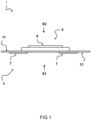
- the wearable patch has a flexible foil 11 that has an adhesive layer 13 on a side for attachment to the skin of the user.
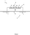
- Fig. 2 shows a schematic diagram of a cross-sectional view of an embodiment of a health data collecting wearable patch 1 with an ECG sensor 3 with electrodes 7 on the skin-attachable bottom side, and a PPG sensor 5 with an optical window 9 on the opposite/top side.
- the wearable patch 1 has an electronic unit 15.
- the electronic unit 15 includes readout electronic arrangements.
- the electronic unit 15 may comprise one or more power sources.
- the electronic unit 15 may include a rechargeable battery unit.
- the electronic unit 15 may include one or more other sensors, such as accelerometers, temperature sensors, electronic gyroscope unit, etc.
- the PPG sensor 5 has a transparent optical window 9.
- the optical window 9 may be made of glass or other suitable materials.
- the PPG sensor 5 has two light emitting units 17, such as light emitting diodes (LEDs), and two optical sensors 19, such as photodiodes.
- LEDs light emitting diodes
- optical sensors 19 such as photodiodes.
- the flexible foil 11 is a skin contact patch.
- skin contact electrodes 7 of the ECG sensor 3 are arranged.
- the wearable patch forms an integrated wearable device.
- the wearable patch integrates an optical PPG module with LEDs of multiple wavelengths and one or more photodiodes on the top surface of the health patch device.
- patients are required to place their fingers to cover the optical window on the device. Once the finger is placed on the device, depending on the skin type and/or other predetermined light-skin interaction models, a particular wavelength of LED light is enabled in the PPG module. The reflected light from the skin is measured by one or more photodiodes located on the top surface of the device.
- the wearable device 1 includes one or more other sensing elements such as bio-impedance, temperature sensor that requires electrodes to be in contact with the skin and other sensing elements such as a microphone that requires close proximity to the body.
- the PPG module includes one or more LEDs of different wavelengths (Blue, Green, Red and Infra-red) and one or more photodiodes to measure the reflected light from the skin.
- the device 1 can be worn on the torso on the chest or the lateral left side of the body depending on the clinical requirements.
- the patient will place a finger on top of the device.
- the LED gets activated, the reflected light from the finger will be measured by photodiodes in the center of the PPG module.
- a particular wavelength of LED light will be used for measurement.
- One or more LEDs can be used in sequence and the best signal output with low signal-to-noise ratio depending on the skin type can be used for SPO2 calculation.
- a capacitive touch sensor can be included in the PPG module to activate the LED lights on contact.
- other mechanisms may also be used.
- a particular protocol for activation such a single-tap or double-tap can be incorporated in the measurement protocol to avoid accidental light activation.
- the PPG signal from this integrated device can also be used for measuring the time lapsed heart rate compared to the electrodes on the bottom of the device and can thus be used for computing the pulse arrival time or pulse transit time.
- SPO2 spot measurements can be simplified.
- a wearable device used for continuous electrophysiological measurements can now be used for SPO2 measurement as well.
- the PPG module can be enabled on demand whenever a measurement needs to be performed.
- the data from the PPG module can be streamlined and transferred along with the rest of the wearable device data.
- the data can be timestamped and correlated accurately to measure Pulse Arrival Time (PAT) in a single device.
- PAT Pulse Arrival Time
- Fig. 3 shows a schematic diagram of a top view of an embodiment of a wearable patch 1.
- the shapes and dimensions of the wearable patch may vary.
- the outer shape of the flexible foil 11 may be different
- the shape of the optical window 9 may be different (e.g. rounded)
- the electronic unit 15 may be smaller relative to the optical window 9, etc.
- Various other configurations are envisaged.
- the wearable patch 1 can effectively avoid inherent complexities of synchronizing data streams, and the reliance on error-prone algorithms for synchronization. Furthermore, the inconvenience of managing multiple devices, and the vulnerabilities to external disruptions can be avoided.
- the wearable patch may have a common device clock.
- both ECG and PPG measurements have the same time resolution.
- both measurements may be sampled at precisely defined intervals, ensuring that the timestamps for both are congruent.
- Fig. 4 shows a schematic diagram of an embodiment of a wearable patch 1.
- the patch is configured to be worn on the torso, for example on a chest 20a and/or a lateral left side 20b of the body.
- two fingers are placed on the optical window 9 of the PPG sensor of the wearable patch 1.
- the integrated ECG and PPG sensors can have a shared reference time point. Potential synchronization challenges due to potential time lags, misalignments, or discrepancies inherent to each device's separate recording, can be effectively prevented.
- the ECG sensor 3 comprises electrodes positioned on the bottom side of the wearable patch 1, making direct contact with the user's skin when attached. Oppositely, the PPG sensor 5, equipped with an optical window 9, is oriented on the patch's opposing side. This configuration facilitates simultaneous data collection from both sensors while the patch is worn, ensuring a shared reference time point.
- the wearable patch inherently provides synchronized readings from both the ECG and PPG sensors. This design eliminates the necessity for, and inherent risks associated with, the deployment of additional synchronization tools. By doing so, the device ensures higher data accuracy and reliability, vital for health monitoring applications where precision is important.
- the consolidated architecture with shared reference time point and streamlined approach not only enhances the efficiency of data collection but also ensures that potential errors, misalignments, or discrepancies, which can compromise the interpretation and utility of the collected data, are substantially minimized.
- Fig. 5 shows a schematic diagram of a method 100 for collecting health-related data using a wearable patch.
- a wearable patch comprising an ECG sensor and PPG sensor is provided, wherein electrodes of the ECG sensor are arranged on a bottom side of the patch, and wherein an optical window of the PPG sensor is arranged on an opposite side of the patch.
- the wearable patch is attached to a skin of a user such that electrodes of the ECG sensor on the bottom side of the patch is positioned in contact with the skin of the user.
- electrocardiogram data via the ECG sensor is collected, and photoplethysmogram data via the PPG sensor is collected.
- the collected electrocardiogram data and photoplethysmogram data is transmitted to a processing device for analysis and monitoring of health-related metrics.
- various parameters such as ECG, heart rate, and breathing rate, etc. can be measured by means of the wearable patch.
- electrical electrodes may be arranged for measuring electrical signals.
- an optical window may be arranged, which can for instance integrate photodiodes and LEDs. In some examples, measurements can be achieved with a single finger for optical readings. But, for combining electrical and optical signals, two fingers might be necessary in some examples.
- the wearable patch can be made from a stretchable material, providing flexibility (e.g. flexible foil).
- the patch can be designed to be attached to the body.
- the wearable patch may be configured to be attached to the middle section of the torso or the lateral left side of the body. This ensures a stable position with minimal motion interference.
- the patch may be dimensioned and/or shaped to facilitate such attachment.
- ECG an electrical signal representing the heart's electrical activity
- PPG an optical signal that measures pulse rate using light
- ECG an electrical signal representing the heart's electrical activity
- PPG an optical signal that measures pulse rate using light
- an internal clock may be employed to synchronize the two sensors. This synchronization ensures that any deviation in the measurement is due to the signal and not internal shifts.
- the wearable patch can provide two reference points for measuring the pulse's transition.
- the wearable patch according to the disclosure provides for a unified device with a single master clock.
- This device would house both the ECG and PPG sensors.
- the ECG and PPG signals can be seamlessly synchronized. This eliminates the inconsistencies that might arise from using two separate devices with their own clocks.
- the device's user-friendly design would allow activation via finger touch, removing the need for auxiliary activation methods or external applications.
- the wearable patch may also integrate one or more other sensors.
- One exemplary sensor is a bioimpedance sensor. Bioimpedance indicates changes in the impedance of the body, which fluctuates as an individual breathes. This can be a potential diagnostic tool, as changes in bioimpedance could suggest fluid accumulation in the lungs, possibly due to conditions like asthma.
- the wearable patch may be configured to have one or more sensors to determine a value indicative of a respiratory rate. This can be important for assessing the general condition of the patient.
- the wearable patch is waterproof.
- the wearable patch has one or more electrical ECG sensors on its top side.
- the wearable patch may have five electrodes for ECG measurements: two at the top, two at the bottom, and a reference electrode in the middle.
- the bottom electrodes are used to measure respiratory rates using bioimpedance techniques.
- the method may include computer implemented steps. All above mentioned steps can be computer implemented steps.
- Embodiments may comprise computer apparatus, wherein processes performed in computer apparatus.
- the invention also extends to computer programs, particularly computer programs on or in a carrier, adapted for putting the invention into practice.
- the program may be in the form of source or object code or in any other form suitable for use in the implementation of the processes according to the invention.
- the carrier may be any entity or device capable of carrying the program.
- the carrier may comprise a storage medium, such as a ROM, for example a semiconductor ROM or hard disk.
- the carrier may be a transmissible carrier such as an electrical or optical signal which may be conveyed via electrical or optical cable or by radio or other means, e.g. via the internet or cloud.
- Some embodiments may be implemented, for example, using a machine or tangible computer-readable medium or article which may store an instruction or a set of instructions that, if executed by a machine, may cause the machine to perform a method and/or operations in accordance with the embodiments.
- Various embodiments may be implemented using hardware elements, software elements, or a combination of both.
- hardware elements may include processors, microprocessors, circuits, application specific integrated circuits (ASIC), programmable logic devices (PLD), digital signal processors (DSP), field programmable gate array (FPGA), logic gates, registers, semiconductor device, microchips, chip sets, et cetera.
- software may include software components, programs, applications, computer programs, application programs, system programs, machine programs, operating system software, mobile apps, middleware, firmware, software modules, routines, subroutines, functions, computer implemented methods, procedures, software interfaces, application program interfaces (API), methods, instruction sets, computing code, computer code, et cetera.
- API application program interfaces
- any reference signs placed between parentheses shall not be construed as limiting the claim.
- the word 'comprising' does not exclude the presence of other features or steps than those listed in a claim.
- the words 'a' and 'an' shall not be construed as limited to 'only one', but instead are used to mean 'at least one', and do not exclude a plurality.
- the term "and/or" includes any and all combinations of one or more of the associated listed items. The mere fact that certain measures are recited in mutually different claims does not indicate that a combination of these measures cannot be used to an advantage.
Landscapes
- Health & Medical Sciences (AREA)
- Life Sciences & Earth Sciences (AREA)
- Cardiology (AREA)
- Engineering & Computer Science (AREA)
- Medical Informatics (AREA)
- Animal Behavior & Ethology (AREA)
- Pathology (AREA)
- Physics & Mathematics (AREA)
- Biomedical Technology (AREA)
- Heart & Thoracic Surgery (AREA)
- Veterinary Medicine (AREA)
- Molecular Biology (AREA)
- Surgery (AREA)
- Biophysics (AREA)
- General Health & Medical Sciences (AREA)
- Public Health (AREA)
- Physiology (AREA)
- Computer Networks & Wireless Communication (AREA)
- Signal Processing (AREA)
- Vascular Medicine (AREA)
- Measurement Of The Respiration, Hearing Ability, Form, And Blood Characteristics Of Living Organisms (AREA)
- Measuring Pulse, Heart Rate, Blood Pressure Or Blood Flow (AREA)
Priority Applications (2)
| Application Number | Priority Date | Filing Date | Title |
|---|---|---|---|
| EP23212779.5A EP4563076A1 (fr) | 2023-11-28 | 2023-11-28 | Timbre portable pour collecter des données liées à la santé, et procédé de collecte de données synchronisées avec ledit timbre |
| PCT/NL2024/050634 WO2025116725A1 (fr) | 2023-11-28 | 2024-11-26 | Timbre pouvant être porté pour collecter des données liées à la santé, et procédé de collecte de données synchronisées avec ledit timbre |
Applications Claiming Priority (1)
| Application Number | Priority Date | Filing Date | Title |
|---|---|---|---|
| EP23212779.5A EP4563076A1 (fr) | 2023-11-28 | 2023-11-28 | Timbre portable pour collecter des données liées à la santé, et procédé de collecte de données synchronisées avec ledit timbre |
Publications (1)
| Publication Number | Publication Date |
|---|---|
| EP4563076A1 true EP4563076A1 (fr) | 2025-06-04 |
Family
ID=88978475
Family Applications (1)
| Application Number | Title | Priority Date | Filing Date |
|---|---|---|---|
| EP23212779.5A Pending EP4563076A1 (fr) | 2023-11-28 | 2023-11-28 | Timbre portable pour collecter des données liées à la santé, et procédé de collecte de données synchronisées avec ledit timbre |
Country Status (2)
| Country | Link |
|---|---|
| EP (1) | EP4563076A1 (fr) |
| WO (1) | WO2025116725A1 (fr) |
Citations (4)
| Publication number | Priority date | Publication date | Assignee | Title |
|---|---|---|---|---|
| US20150025393A1 (en) * | 2012-06-22 | 2015-01-22 | Fitbit, Inc. | Wearable heart rate monitor |
| US20170020399A1 (en) * | 2015-06-02 | 2017-01-26 | Sportracker Ltd. | Methods Circuits Assemblies Devices Systems and Associated Machine Executable Code for Biological Sensing |
| US20180116605A1 (en) * | 2015-09-25 | 2018-05-03 | Sanmina Corporation | Vehicular health monitoring system and method |
| US20200352510A1 (en) * | 2019-05-08 | 2020-11-12 | Baxter International Inc. | Patch-based physiological sensor |
-
2023
- 2023-11-28 EP EP23212779.5A patent/EP4563076A1/fr active Pending
-
2024
- 2024-11-26 WO PCT/NL2024/050634 patent/WO2025116725A1/fr active Pending
Patent Citations (4)
| Publication number | Priority date | Publication date | Assignee | Title |
|---|---|---|---|---|
| US20150025393A1 (en) * | 2012-06-22 | 2015-01-22 | Fitbit, Inc. | Wearable heart rate monitor |
| US20170020399A1 (en) * | 2015-06-02 | 2017-01-26 | Sportracker Ltd. | Methods Circuits Assemblies Devices Systems and Associated Machine Executable Code for Biological Sensing |
| US20180116605A1 (en) * | 2015-09-25 | 2018-05-03 | Sanmina Corporation | Vehicular health monitoring system and method |
| US20200352510A1 (en) * | 2019-05-08 | 2020-11-12 | Baxter International Inc. | Patch-based physiological sensor |
Non-Patent Citations (1)
| Title |
|---|
| GANTI VENU G ET AL: "Wearable Cuff-Less Blood Pressure Estimation at Home via Pulse Transit Time", IEEE JOURNAL OF BIOMEDICAL AND HEALTH INFORMATICS, IEEE, PISCATAWAY, NJ, USA, vol. 25, no. 6, 3 September 2020 (2020-09-03), pages 1926 - 1937, XP011858528, ISSN: 2168-2194, [retrieved on 20210603], DOI: 10.1109/JBHI.2020.3021532 * |
Also Published As
| Publication number | Publication date |
|---|---|
| WO2025116725A1 (fr) | 2025-06-05 |
Similar Documents
| Publication | Publication Date | Title |
|---|---|---|
| US11903700B2 (en) | Vital signs monitoring systems and methods | |
| US11185291B2 (en) | Health monitoring systems and methods | |
| Holz et al. | Glabella: Continuously sensing blood pressure behavior using an unobtrusive wearable device | |
| US10842391B2 (en) | Health monitoring systems and methods | |
| CN114652281B (zh) | 健康监视系统和方法 | |
| US20200237309A1 (en) | Health monitoring systems and methods | |
| US10980486B2 (en) | Health monitoring systems and methods | |
| JP2019072552A (ja) | 個人健康データ収集 | |
| US20140051941A1 (en) | Obtaining physiological measurements using a portable device | |
| US20190142286A1 (en) | Photoplethysmographic wearable blood pressure monitoring system and methods | |
| CN109688914A (zh) | 用于测量血压的单个可穿戴设备系统 | |
| WO2014022906A1 (fr) | Système de dispositif mobile pour une mesure de santé cardio-vasculaire | |
| CA2935160A1 (fr) | Procedes, systemes, et dispositifs pour le positionnement optimal de capteurs | |
| EP3313287A1 (fr) | Systèmes et méthodes de surveillance de la santé | |
| JP2019526293A (ja) | 心拍数測定方法、心拍数測定装置及び装着可能装置 | |
| US20230172499A1 (en) | Vital signs or health monitoring systems and methods | |
| US20220225945A1 (en) | Health monitoring systems and methods | |
| CN107334467A (zh) | 血压检测手表 | |
| JP7133576B2 (ja) | 位相差法による連続血圧測定システム | |
| EP4563076A1 (fr) | Timbre portable pour collecter des données liées à la santé, et procédé de collecte de données synchronisées avec ledit timbre | |
| US20240366095A1 (en) | Technologies for multimodal sensor wearable device for biomedical monitoring | |
| WO2024093723A1 (fr) | Montre intelligente et procédé de mesure de données physiologiques | |
| EP4563074A1 (fr) | Système modulaire et procédé de synchronisation de collecte de données de santé à capteurs multiples | |
| US20220378308A1 (en) | Method And Device That Monitors A Fetal Heart Rate | |
| US20240164687A1 (en) | System and Method for Blood Pressure Assessment |
Legal Events
| Date | Code | Title | Description |
|---|---|---|---|
| PUAI | Public reference made under article 153(3) epc to a published international application that has entered the european phase |
Free format text: ORIGINAL CODE: 0009012 |
|
| STAA | Information on the status of an ep patent application or granted ep patent |
Free format text: STATUS: THE APPLICATION HAS BEEN PUBLISHED |
|
| AK | Designated contracting states |
Kind code of ref document: A1 Designated state(s): AL AT BE BG CH CY CZ DE DK EE ES FI FR GB GR HR HU IE IS IT LI LT LU LV MC ME MK MT NL NO PL PT RO RS SE SI SK SM TR |
|
| STAA | Information on the status of an ep patent application or granted ep patent |
Free format text: STATUS: REQUEST FOR EXAMINATION WAS MADE |
|
| 17P | Request for examination filed |
Effective date: 20251204 |