EP4563103A1 - Ensemble de centrage avec vis de verrouillage - Google Patents
Ensemble de centrage avec vis de verrouillage Download PDFInfo
- Publication number
- EP4563103A1 EP4563103A1 EP24215791.5A EP24215791A EP4563103A1 EP 4563103 A1 EP4563103 A1 EP 4563103A1 EP 24215791 A EP24215791 A EP 24215791A EP 4563103 A1 EP4563103 A1 EP 4563103A1
- Authority
- EP
- European Patent Office
- Prior art keywords
- outer sleeve
- centering unit
- sleeve
- proximal
- distal
- Prior art date
- Legal status (The legal status is an assumption and is not a legal conclusion. Google has not performed a legal analysis and makes no representation as to the accuracy of the status listed.)
- Pending
Links
Images
Classifications
-
- A—HUMAN NECESSITIES
- A61—MEDICAL OR VETERINARY SCIENCE; HYGIENE
- A61B—DIAGNOSIS; SURGERY; IDENTIFICATION
- A61B17/00—Surgical instruments, devices or methods
- A61B17/56—Surgical instruments or methods for treatment of bones or joints; Devices specially adapted therefor
- A61B17/58—Surgical instruments or methods for treatment of bones or joints; Devices specially adapted therefor for osteosynthesis, e.g. bone plates, screws or setting implements
- A61B17/68—Internal fixation devices, including fasteners and spinal fixators, even if a part thereof projects from the skin
- A61B17/70—Spinal positioners or stabilisers, e.g. stabilisers comprising fluid filler in an implant
- A61B17/7074—Tools specially adapted for spinal fixation operations other than for bone removal or filler handling
- A61B17/7091—Tools specially adapted for spinal fixation operations other than for bone removal or filler handling for applying, tightening or removing longitudinal element-to-bone anchor locking elements, e.g. caps, set screws, nuts or wedges
-
- A—HUMAN NECESSITIES
- A61—MEDICAL OR VETERINARY SCIENCE; HYGIENE
- A61B—DIAGNOSIS; SURGERY; IDENTIFICATION
- A61B17/00—Surgical instruments, devices or methods
- A61B17/56—Surgical instruments or methods for treatment of bones or joints; Devices specially adapted therefor
- A61B17/58—Surgical instruments or methods for treatment of bones or joints; Devices specially adapted therefor for osteosynthesis, e.g. bone plates, screws or setting implements
- A61B17/68—Internal fixation devices, including fasteners and spinal fixators, even if a part thereof projects from the skin
- A61B17/70—Spinal positioners or stabilisers, e.g. stabilisers comprising fluid filler in an implant
- A61B17/7074—Tools specially adapted for spinal fixation operations other than for bone removal or filler handling
- A61B17/7076—Tools specially adapted for spinal fixation operations other than for bone removal or filler handling for driving, positioning or assembling spinal clamps or bone anchors specially adapted for spinal fixation
- A61B17/7077—Tools specially adapted for spinal fixation operations other than for bone removal or filler handling for driving, positioning or assembling spinal clamps or bone anchors specially adapted for spinal fixation for moving bone anchors attached to vertebrae, thereby displacing the vertebrae
- A61B17/708—Tools specially adapted for spinal fixation operations other than for bone removal or filler handling for driving, positioning or assembling spinal clamps or bone anchors specially adapted for spinal fixation for moving bone anchors attached to vertebrae, thereby displacing the vertebrae with tubular extensions coaxially mounted on the bone anchors
Definitions
- the present disclosure relates to a centering unit for an assembly tool, preferably in the form of a screwdriver, which is provided and designed for inserting a grub screw into the tulip of a pedicle screw.
- a pedicle screw Basically, mono- and polyaxial pedicle screws exist in the state of the art, which are designed to be screwed into a vertebral bone.
- a pedicle screw generally has a shaft with an external thread, at the proximal end/end section of which a so-called tulip is fixed (monoaxial design) or movably mounted, namely pivotably and rotatably, on a distal shaft head (polyaxial design).
- a tulip is, in simpler terms, a tubular socket whose walls are longitudinally slit at two diametrically opposed circumferential sections, such that the slits open proximally (away from the shaft) at the tulip end, thus each having a U-shape.
- the tube socket On the inside of the tulip, the tube socket has an internal thread into which a so-called grub screw is or can be screwed from the proximal end of the tulip.
- the grub screw is/can be placed against a connecting rod, which is inserted into the opposite slots and connects at least two pedicle screws of two vertebrae spaced apart in the longitudinal direction of the spine, in order to fix the position of these at least two vertebrae relative to each other.
- the grub screw presses the inserted connecting rod against the distal end of the tulip (monoaxial design) or against the proximal shaft head (polyaxial design) and clamps it.
- the internal thread of the tulip is designed in such a way that it acts as a type of Self-locking is achieved, making it unlikely that the clamped rod will come loose (unintentionally).
- an Allen key for example, is inserted through the tulip, which is open at the proximal end, and into a corresponding polygonal blind hole at the proximal end section of the pedicle screw shaft to screw the shaft into the vertebral bone.
- the aforementioned connecting rod is then inserted into the tulip, and the grub screw is screwed into the tulip's internal thread.
- the DE 10 2011 053 295 A1 already discloses an assembly aid to simplify the aforementioned implantation process, particularly when using polyaxial pedicle screws.
- This assembly aid essentially has an inner sleeve, which is pressed axially against the proximal shaft head on the inside of the tulip.
- the assembly aid has an outer sleeve that surrounds the tulip on the outside and engages in an external tulip slot or groove.
- a clamping device is provided, for example in the form of a union nut, via which the inner sleeve can be axially adjusted relative to the outer sleeve.
- the above-mentioned assembly aid can also help to facilitate the insertion/placement of the grub screw into/onto the internal thread of the tulip by preventing or at least making it more difficult for the grub screw to become jammed.
- the tool for tightening the grub screw must be inserted into the The already clamped inner sleeve must be inserted axially.
- this also requires the grub screw to be temporarily held on the tool in such a way that the grub screw cannot accidentally fall off or be knocked off when the tool is inserted into the inner sleeve. This poses problems in the current state of the art.
- the core of the present disclosure consists in the arrangement of a (medical) centering unit with an outer sleeve, in which an axially acting spring device (preloading means) is inserted, for example in the form of a helical spring, a number of (axially aligned) disc springs, a sleeve made of an elastic material (rubber, plastic, etc.), or similar preloading means, which is supported in the distal direction on a shoulder on the inside of the sleeve (distal spring seat).
- preloading means for example in the form of a helical spring, a number of (axially aligned) disc springs, a sleeve made of an elastic material (rubber, plastic, etc.), or similar preloading means, which is supported in the distal direction on a shoulder on the inside of the sleeve (distal spring seat).
- the spring device is provided and designed to exert an axial preload force on a tool inserted into the outer sleeve (which is designed to place and tighten a grub screw on/in a tulip of a pedicle screw) as soon as the tool is axially displaced in the outer sleeve beyond a predetermined amount (relative to the outer sleeve).
- the outer sleeve according to the disclosure has a distal contact section (distal front edge) which is intended and designed to be axially applied against the tulip (as a force abutment) in such a way that when an axial force is applied to the tool in the distal direction, the tool can be displaced relative to the outer sleeve against the spring preload to such an extent that the distal tool tip can (or protrudes) beyond the distal front edge of the outer sleeve (and thus into the tulip).
- the centering unit described above is first placed onto a tool shaft.
- a tool shaft This is preferably provided with, or can be provided with, an axial stop (proximal spring seat), the longitudinal position of which is selected or can be selected such that the outer sleeve, in the design position relative to the tool shaft (without external/manual axial force being applied to the tool), radially surrounds the distal tip of the tool shaft and preferably even protrudes axially beyond the distal tip of the tool shaft.
- the grub screw can now be placed onto the distal tip of the tool shaft, protected from lateral/radial blows or impacts by the outer sleeve (which circumferentially surrounds the tool shaft tip).
- the tool including the grub screw and the outer sleeve of the centering unit radially surrounding it, is brought up to the proximal tulip end face of the already implanted pedicle screw, and the outer sleeve is pressed axially against the tulip.
- the tool is axially displaced relative to the outer sleeve against the preload force of the preloading device inserted into the outer sleeve (the preloading device is clamped between the distal spring seat on the outer sleeve and the proximal spring seat, preferably on the tool shank), whereby the grub screw is inserted beyond the distal end edge of the outer sleeve (essentially without jamming) into the tulip.
- the tool only needs to be rotated within the outer sleeve (while maintaining the axial clamping force) to tighten the grub screw within the tulip.
- an inner sleeve is inserted or insertable in an axially displaceable manner at the proximal end section of the outer sleeve, which inner sleeve is supported in the distal direction against the preloading means.
- the inner sleeve can be connected proximally to the preloading means or at least partially protrude radially inward into the preloading means, preferably in the form of a helical compression spring, in order to preferably radially support the preloading means.
- the inner sleeve is formed with at least one radially outwardly projecting circumferential projection, which serves as a proximal axial stop (proximal spring seat) for the preloading means.
- the axial stop on the tool shank serves no longer directly as a proximal spring seat, but rather as a stop for the inner sleeve, which in turn forms the proximal spring seat.
- the inner sleeve can preferably be designed with an additional radially outwardly projecting proximal projection, which serves as a movement stop in the proximal direction and can be brought into contact with an undercut on the radial inside of the outer sleeve.
- the centering unit forms a quasi-self-contained component, in which the spring device (preloading means) is inserted between the distal and proximal spring seat within the centering unit with or without preload. Proximal falling out of the spring device (preloading means) from the outer sleeve is prevented by the inner sleeve.
- the inner diameter of the inner sleeve can be matched to the tool shank such that it is supported in the inner sleeve with minimal play. This contributes to even more secure/improved (tilting-free) screwing in of the grub screw.
- an engagement arm is pivotally mounted on the outer sleeve on at least two diametrically opposed circumferential sections.
- Each engagement arm extends in the outer sleeve's longitudinal direction and, in its longitudinal center section, is hinged in a rocker-like manner to a respective bearing block that is fixed or formed on the radial outer side of the outer sleeve.
- Each engagement arm is preloaded by a spring such that its distal end is pressed radially inward (and consequently its proximal end radially outward).
- the spring can either be a helical compression spring, which is supported radially outward against the outer sleeve proximal to the bearing block below the respective engagement arm, or a spiral spring wound around the hinge axis, one spring end of which bears against the outer sleeve and the other spring end of which bears against the respective engagement arm proximal to the bearing block.
- each engagement arm has a distal engagement portion which is provided and designed to form a contact with the outer peripheral side of the tulip. and/or frictionally engage to hold the outer sleeve on the proximal end face of the tulip and, if necessary, to center it.
- the arm section proximal to the respective bearing block preferably forms an actuating branch, whereby the distal engagement section can be moved radially outward against the spring preload force.
- the inner side of the outer sleeve forms a radially widened receiving space in a distal sleeve section for (contactless) receiving the grub sleeve (i.e., the tool shank tip with attached grub screw).
- the receiving space narrows/tapers in the proximal direction to an inner radius that is adapted either to the outer radius of the tool shank or the inner sleeve.
- a resulting outer sleeve axial section with a narrowed inner radius forms a radial widening on the outer sleeve inner side at its proximal end (approximately in the axial center section of the outer sleeve), resulting in a proximally directed contact edge (distal spring seat) for the spring device/preloading means (helical spring).
- the proximal spring stop/spring seat is dimensioned either on the tool shaft or on the inner sleeve so that it slides circumferentially against the inside of the outer sleeve.
- the outer sleeve is guided at two axially spaced locations, namely in the area of the distal outer sleeve axial section with a narrowed inner radius and in the area of the proximal spring stop/spring seat, and thus centered with respect to the inserted tool shaft.
- a holder for example in the form of a holding sleeve, can be fastened to the proximal end section of the outer sleeve (for example by latching, screwing, or similar detachable connections), which is intended to be brought into axial operative engagement with the tool shank as a kind of pull-off protection.
- the sleeve nut can have radially inwardly projecting clamping feet or clamping feet that can be elastically slipped over the proximal axial stop (possibly a spring seat) on the tool shank, or the holding sleeve has a radially inwardly projecting axial contact section that can be brought into contact with the proximal axial stop (possibly a spring seat) on the tool shank on its proximal side in order to prevent the centering unit from accidentally falling off the already inserted tool shank.
- the retaining sleeve must be mounted on the tool shank from the proximal side of the proximal axial stop (spring seat if applicable) or must first be placed on the tool shank before the proximal axial stop (spring seat if applicable) is mounted/fixed on the tool shank.
- the inner sleeve can be provided, particularly at its proximal end edge, with a radially outwardly projecting collar, which limits the axial displacement of the inner sleeve relative to the outer sleeve distally against the preload force of the spring device/spring means when the collar comes into contact with the proximal end edge of the outer sleeve. In this case, complete compression of the spring device can be avoided.
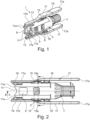
- a distal end section of the outer sleeve 3 (facing towards a pedicle screw) has a lattice structure with a number of radial openings 9, through which a circumferential view into the distal interior of the outer sleeve 3 can be obtained. Furthermore, two diametrically opposed partial circular arcs 11 are formed on the distal end edge of the outer sleeve 3, whereby four circumferentially spaced support corners 11a are formed, which extend in the distal direction.
- two notches 13 are incorporated on the distal end edge of the outer sleeve 3, which are therefore also diametrically opposed to one another, which essentially have a rectangular shape and preferably extend further in the proximal direction (notch depth) than the partial circular arcs 11.
- a bearing block 15 is arranged/formed on the outer circumferential side of the outer sleeve 3.
- an engagement arm 17 is hinged in a rocker-like manner, which extends coaxially to the outer sleeve 3 and by one spring (helical compression spring) 19 in accordance with the Fig. 1 are preloaded counterclockwise.
- engagement profiles 19 are arranged at the distal end section of each engagement arm 17 or the associated distal arm section 17b, which are provided and designed to come into frictional and/or positive engagement with the outer side of a pedicle screw-side tulip (as defined above).
- the engagement profiles 19 are dimensioned and positioned such that they are in the design position according to the Fig. 2 at least partially radially into the notches 13. This is particularly the case in the Fig. 2
- the engagement arms 17 form a step in the longitudinal section transverse to the hinge axis 15a of the bearing blocks 15, whereby the proximal arm section 17a in the design position according to the Fig.
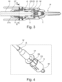
- the outer sleeve 3 forms in its distal end section a distally open receiving space 21 with an enlarged diameter, which is designed to at least partially, preferably completely receive a maggot sleeve M, which is intended for screwing into the tulip T of a pedicle screw P according to the prior art.
- the proximal end region of the receiving space 21 is defined by a radially tapered outer sleeve axial section 23, the inside of which represents a guide sliding bearing for an inserted tool shaft W.
- the helical compression spring 5 is intended and designed to come into contact with a stop edge A defining a proximal spring seat on the side of the tool shaft W when the tool shaft W is inserted distally into the outer sleeve 3.
- a retaining component 27 is mounted on the proximal end portion of the outer sleeve 3, for example by screwing or locking it onto the outer sleeve 3, which retaining component has a radially inwardly projecting holding or stop portion 27a.
- This holding or stop portion 27a is provided and dimensioned to engage with a radially outwardly directed projection V on the side of the tool shank W in the distal direction in order to prevent the centering unit 1 from accidentally falling off the tool shank W, possibly triggered by the spring device 5.
- the function of the centering unit 1 can be summarized as follows: First, the retaining component (holder) 27 is pushed from the proximal side onto the tool shaft W, after which the outer sleeve 3 is pushed from the distal side onto the tool shaft W. The retaining component 27 and the outer sleeve 3 are connected to each other as shown in the Fig. 3 is shown. In this design position, the spring device 5 is relaxed or only slightly preloaded, with the distal tip of the tool shaft W protruding into the receiving space 21. A grub screw M can now be attached to the distal tip in a rotationally fixed manner.
- the tool prepared in this way is guided into the surgical area in the patient and placed axially onto the tulip T of the pedicle screw P already screwed into the conch. placed on.
- the support corners 11a come into axial contact with a peripheral edge on the tulip T.
- the two engagement arms 17 are manually actuated so that the distal engagement sections/engagement profiles 19 engage around the outer circumference of the tulip, whereupon the engagement arms 17 are released and are pressed circumferentially against the tulip T by the pretensioning force of the springs 19.
- the engagement profiles 19 come into frictional and/or locking engagement with the tulip T and thus hold the centering unit 1 firmly on the tulip T.
- the tool can be pushed axially toward the tulip T, whereby the spring device 5 is elastically compressed.
- This pushing movement is guided by the outer sleeve 3, so that tilting of the grub screw M at the beginning of the screwing-in process is almost impossible.
- the Fig. 4 shows the external structure of a centering unit 1 according to a second preferred embodiment of the disclosure.
- an inner sleeve 29 is provided, which is inserted into the outer sleeve 3 from the proximal side.
- the inner sleeve 29 has a radially outwardly projecting stop projection (not shown) comparable to the proximal stop edge A on the side of the tool shank W, as shown in Fig. 3 is shown.
- the inner sleeve 29 forms the proximal spring seat for the spring device 5, whereby the inner sleeve 29 can then be axially supported on the proximal stop edge A on the side of the tool shank W.
- the inner sleeve 29 has a circumferential collar 31 in a proximal section, which serves as a push-forward travel limiter and can be brought into contact with the proximal end face of the outer sleeve 3.
- the inner sleeve 29 has a radially outwardly projecting projection (in Fig. 4 not visible) which can be brought into axial contact with a radially inwardly projecting projection 33 in order to prevent the inner sleeve 29 from being pressed out of the outer sleeve 3 in the proximal direction by the spring device 5.
- the inner sleeve 29 therefore serves as an axial spacer of the spring seat A on the tool shank side into the centering unit 1, whereby in this case the inner diameters of the outer sleeve 3 acting as plain bearings no longer have to be individually adapted to the tool shank W, but are set up for the outer diameter of the inner sleeve 29 as a component of the centering unit 1.
- the present disclosure relates to a centering unit (1) intended and configured for medical purposes for a screwing-in tool (W) for screwing a grub screw (M) into the tulip (T) of a pedicle screw (P), wherein the centering unit (1) has an outer sleeve (3) and a spring device (5) acting in the axial direction of the outer sleeve (3), which is inserted or inserted into the outer sleeve (3) and which is supported in the distal direction on a shoulder serving as a spring seat on the inside of the outer sleeve (3).
Landscapes
- Health & Medical Sciences (AREA)
- Orthopedic Medicine & Surgery (AREA)
- Neurology (AREA)
- Life Sciences & Earth Sciences (AREA)
- Surgery (AREA)
- Heart & Thoracic Surgery (AREA)
- Engineering & Computer Science (AREA)
- Biomedical Technology (AREA)
- Nuclear Medicine, Radiotherapy & Molecular Imaging (AREA)
- Medical Informatics (AREA)
- Molecular Biology (AREA)
- Animal Behavior & Ethology (AREA)
- General Health & Medical Sciences (AREA)
- Public Health (AREA)
- Veterinary Medicine (AREA)
- Surgical Instruments (AREA)
Applications Claiming Priority (1)
| Application Number | Priority Date | Filing Date | Title |
|---|---|---|---|
| DE102023133254.6A DE102023133254A1 (de) | 2023-11-28 | 2023-11-28 | Zentriereinheit Verriegelungsschraube |
Publications (1)
| Publication Number | Publication Date |
|---|---|
| EP4563103A1 true EP4563103A1 (fr) | 2025-06-04 |
Family
ID=93705082
Family Applications (1)
| Application Number | Title | Priority Date | Filing Date |
|---|---|---|---|
| EP24215791.5A Pending EP4563103A1 (fr) | 2023-11-28 | 2024-11-27 | Ensemble de centrage avec vis de verrouillage |
Country Status (2)
| Country | Link |
|---|---|
| EP (1) | EP4563103A1 (fr) |
| DE (1) | DE102023133254A1 (fr) |
Citations (6)
| Publication number | Priority date | Publication date | Assignee | Title |
|---|---|---|---|---|
| WO2008024937A2 (fr) * | 2006-08-23 | 2008-02-28 | Pioneer Surgical Technology, Inc. | Système chirurgical à effraction minimale |
| US20110184469A1 (en) * | 2010-01-28 | 2011-07-28 | Warsaw Orthopedic, Inc. | Set screw alignment tool |
| DE102011053295A1 (de) | 2011-09-06 | 2013-03-07 | Aesculap Ag | Polyaxiale Pedikelschraube mit provisorischer Fixierung |
| US20170143385A1 (en) * | 2015-11-19 | 2017-05-25 | K2M, Inc. | Spinal rod reduction system |
| US20220133360A1 (en) * | 2019-02-27 | 2022-05-05 | Lenkbar Llc | Spinal Fixation Assembly |
| WO2022184798A1 (fr) * | 2021-03-05 | 2022-09-09 | Medos International Sarl | Réducteur séquentiel |
-
2023
- 2023-11-28 DE DE102023133254.6A patent/DE102023133254A1/de active Pending
-
2024
- 2024-11-27 EP EP24215791.5A patent/EP4563103A1/fr active Pending
Patent Citations (6)
| Publication number | Priority date | Publication date | Assignee | Title |
|---|---|---|---|---|
| WO2008024937A2 (fr) * | 2006-08-23 | 2008-02-28 | Pioneer Surgical Technology, Inc. | Système chirurgical à effraction minimale |
| US20110184469A1 (en) * | 2010-01-28 | 2011-07-28 | Warsaw Orthopedic, Inc. | Set screw alignment tool |
| DE102011053295A1 (de) | 2011-09-06 | 2013-03-07 | Aesculap Ag | Polyaxiale Pedikelschraube mit provisorischer Fixierung |
| US20170143385A1 (en) * | 2015-11-19 | 2017-05-25 | K2M, Inc. | Spinal rod reduction system |
| US20220133360A1 (en) * | 2019-02-27 | 2022-05-05 | Lenkbar Llc | Spinal Fixation Assembly |
| WO2022184798A1 (fr) * | 2021-03-05 | 2022-09-09 | Medos International Sarl | Réducteur séquentiel |
Also Published As
| Publication number | Publication date |
|---|---|
| DE102023133254A1 (de) | 2025-05-28 |
Similar Documents
| Publication | Publication Date | Title |
|---|---|---|
| EP2286747B1 (fr) | Elément d'ancrage et dispositif de stabilisation dynamique pour vertèbres ou os. | |
| DE102007042959B4 (de) | Chirurgische Halteschraube | |
| EP2347724B1 (fr) | Dispositif de serrage pour éléments chirurgicaux | |
| EP0483242B1 (fr) | Element de reception d'une vis de pedicule, et vis de pedicule | |
| EP1511435B1 (fr) | Element d'ancrage pour fixer une tige d'un dispositif servant a ajuster une colonne vertebrale humaine ou animale sur une vertebre | |
| DE10157814B4 (de) | Verschlußeinrichtung zum Sichern eines stabförmigen Elements in einem mit einem Schaft verbundenen Halteelement | |
| EP2976031B1 (fr) | Système de stabilisation de la colonne vertébrale et élément de fixation chirurgicale pour un système de stabilisation de la colonne vertébrale | |
| EP1061861B1 (fr) | Instrument pour insertion de lames spiroidales | |
| DE19507141B4 (de) | Arretierwerkzeug | |
| EP1372502B1 (fr) | Element d'ancrage | |
| DE102005021879B4 (de) | Orthopädisches Verankerungselement und Osteosynthesevorrichtung | |
| EP0794736B1 (fr) | Element de fixation osteosynthetique | |
| EP3117787A1 (fr) | Vis pediculaire en u | |
| DE102016108504A1 (de) | Medizintechnisches Instrument zur provisorischen Fixierung einer polyaxialen Pedikelschraube | |
| EP1316295A2 (fr) | Elément avec une vis d'ancrage et un élément de retenue relié à la vis pour connecter une barre | |
| WO1998032386A1 (fr) | Dispositif pour connecter un support longitudinal avec une vis pediculaire | |
| EP3269318A1 (fr) | Vis pédiculaire polyaxiale à fixation temporaire | |
| DE29819914U1 (de) | Endoskopisches Einsetzinstrumentarium | |
| EP3383291B1 (fr) | Instrument médical et instrumentation médicale | |
| EP3100691B1 (fr) | Élément d'ancrage d'os uniplanaire | |
| WO2017016717A1 (fr) | Dispositif d'ostéosynthèse | |
| EP1720473B1 (fr) | Systeme de fixation d'os | |
| EP4563103A1 (fr) | Ensemble de centrage avec vis de verrouillage | |
| DE20106723U1 (de) | Modular aufgebaute Knochenraspel oder Modular aufgebautes Schaftimplantat | |
| DE102024109618A1 (de) | Hülse für eine Implantatschraube und Implantatschraube mit einer Hülse |
Legal Events
| Date | Code | Title | Description |
|---|---|---|---|
| PUAI | Public reference made under article 153(3) epc to a published international application that has entered the european phase |
Free format text: ORIGINAL CODE: 0009012 |
|
| STAA | Information on the status of an ep patent application or granted ep patent |
Free format text: STATUS: THE APPLICATION HAS BEEN PUBLISHED |
|
| AK | Designated contracting states |
Kind code of ref document: A1 Designated state(s): AL AT BE BG CH CY CZ DE DK EE ES FI FR GB GR HR HU IE IS IT LI LT LU LV MC ME MK MT NL NO PL PT RO RS SE SI SK SM TR |
|
| STAA | Information on the status of an ep patent application or granted ep patent |
Free format text: STATUS: REQUEST FOR EXAMINATION WAS MADE |
|
| 17P | Request for examination filed |
Effective date: 20251127 |
|
| GRAP | Despatch of communication of intention to grant a patent |
Free format text: ORIGINAL CODE: EPIDOSNIGR1 |
|
| STAA | Information on the status of an ep patent application or granted ep patent |
Free format text: STATUS: GRANT OF PATENT IS INTENDED |
|
| INTG | Intention to grant announced |
Effective date: 20260317 |