EP4563105A2 - Teleskopischer marknagel und kit mit besagtem teleskopischem marknagel und zugehörige werkzeuge - Google Patents
Teleskopischer marknagel und kit mit besagtem teleskopischem marknagel und zugehörige werkzeuge Download PDFInfo
- Publication number
- EP4563105A2 EP4563105A2 EP24216039.8A EP24216039A EP4563105A2 EP 4563105 A2 EP4563105 A2 EP 4563105A2 EP 24216039 A EP24216039 A EP 24216039A EP 4563105 A2 EP4563105 A2 EP 4563105A2
- Authority
- EP
- European Patent Office
- Prior art keywords
- intramedullary nail
- rod
- telescopic
- telescopic intramedullary
- hollow stem
- Prior art date
- Legal status (The legal status is an assumption and is not a legal conclusion. Google has not performed a legal analysis and makes no representation as to the accuracy of the status listed.)
- Pending
Links
Images



Classifications
-
- A—HUMAN NECESSITIES
- A61—MEDICAL OR VETERINARY SCIENCE; HYGIENE
- A61B—DIAGNOSIS; SURGERY; IDENTIFICATION
- A61B17/00—Surgical instruments, devices or methods
- A61B17/56—Surgical instruments or methods for treatment of bones or joints; Devices specially adapted therefor
- A61B17/58—Surgical instruments or methods for treatment of bones or joints; Devices specially adapted therefor for osteosynthesis, e.g. bone plates, screws or setting implements
- A61B17/68—Internal fixation devices, including fasteners and spinal fixators, even if a part thereof projects from the skin
- A61B17/72—Intramedullary devices, e.g. pins or nails
-
- A—HUMAN NECESSITIES
- A61—MEDICAL OR VETERINARY SCIENCE; HYGIENE
- A61B—DIAGNOSIS; SURGERY; IDENTIFICATION
- A61B17/00—Surgical instruments, devices or methods
- A61B17/56—Surgical instruments or methods for treatment of bones or joints; Devices specially adapted therefor
- A61B17/58—Surgical instruments or methods for treatment of bones or joints; Devices specially adapted therefor for osteosynthesis, e.g. bone plates, screws or setting implements
- A61B17/68—Internal fixation devices, including fasteners and spinal fixators, even if a part thereof projects from the skin
- A61B17/72—Intramedullary devices, e.g. pins or nails
- A61B17/7233—Intramedullary devices, e.g. pins or nails with special means of locking the nail to the bone
-
- A—HUMAN NECESSITIES
- A61—MEDICAL OR VETERINARY SCIENCE; HYGIENE
- A61B—DIAGNOSIS; SURGERY; IDENTIFICATION
- A61B17/00—Surgical instruments, devices or methods
- A61B17/16—Instruments for performing osteoclasis; Drills or chisels for bones; Trepans
- A61B17/164—Instruments for performing osteoclasis; Drills or chisels for bones; Trepans intramedullary
-
- A—HUMAN NECESSITIES
- A61—MEDICAL OR VETERINARY SCIENCE; HYGIENE
- A61B—DIAGNOSIS; SURGERY; IDENTIFICATION
- A61B17/00—Surgical instruments, devices or methods
- A61B17/56—Surgical instruments or methods for treatment of bones or joints; Devices specially adapted therefor
- A61B17/58—Surgical instruments or methods for treatment of bones or joints; Devices specially adapted therefor for osteosynthesis, e.g. bone plates, screws or setting implements
- A61B17/68—Internal fixation devices, including fasteners and spinal fixators, even if a part thereof projects from the skin
- A61B17/72—Intramedullary devices, e.g. pins or nails
- A61B17/7233—Intramedullary devices, e.g. pins or nails with special means of locking the nail to the bone
- A61B17/7241—Intramedullary devices, e.g. pins or nails with special means of locking the nail to the bone the nail having separate elements through which screws pass
-
- A—HUMAN NECESSITIES
- A61—MEDICAL OR VETERINARY SCIENCE; HYGIENE
- A61B—DIAGNOSIS; SURGERY; IDENTIFICATION
- A61B17/00—Surgical instruments, devices or methods
- A61B17/56—Surgical instruments or methods for treatment of bones or joints; Devices specially adapted therefor
- A61B17/58—Surgical instruments or methods for treatment of bones or joints; Devices specially adapted therefor for osteosynthesis, e.g. bone plates, screws or setting implements
- A61B17/88—Osteosynthesis instruments; Methods or means for implanting or extracting internal or external fixation devices
- A61B17/8872—Instruments for putting said fixation devices against or away from the bone
-
- A—HUMAN NECESSITIES
- A61—MEDICAL OR VETERINARY SCIENCE; HYGIENE
- A61B—DIAGNOSIS; SURGERY; IDENTIFICATION
- A61B17/00—Surgical instruments, devices or methods
- A61B17/56—Surgical instruments or methods for treatment of bones or joints; Devices specially adapted therefor
- A61B17/58—Surgical instruments or methods for treatment of bones or joints; Devices specially adapted therefor for osteosynthesis, e.g. bone plates, screws or setting implements
- A61B17/88—Osteosynthesis instruments; Methods or means for implanting or extracting internal or external fixation devices
- A61B17/8875—Screwdrivers, spanners or wrenches
-
- A—HUMAN NECESSITIES
- A61—MEDICAL OR VETERINARY SCIENCE; HYGIENE
- A61B—DIAGNOSIS; SURGERY; IDENTIFICATION
- A61B17/00—Surgical instruments, devices or methods
- A61B17/56—Surgical instruments or methods for treatment of bones or joints; Devices specially adapted therefor
- A61B17/58—Surgical instruments or methods for treatment of bones or joints; Devices specially adapted therefor for osteosynthesis, e.g. bone plates, screws or setting implements
- A61B17/88—Osteosynthesis instruments; Methods or means for implanting or extracting internal or external fixation devices
- A61B17/8875—Screwdrivers, spanners or wrenches
- A61B17/8877—Screwdrivers, spanners or wrenches characterised by the cross-section of the driver bit
- A61B17/8883—Screwdrivers, spanners or wrenches characterised by the cross-section of the driver bit the driver bit acting on the periphery of the screw head
-
- A—HUMAN NECESSITIES
- A61—MEDICAL OR VETERINARY SCIENCE; HYGIENE
- A61B—DIAGNOSIS; SURGERY; IDENTIFICATION
- A61B17/00—Surgical instruments, devices or methods
- A61B17/56—Surgical instruments or methods for treatment of bones or joints; Devices specially adapted therefor
- A61B17/58—Surgical instruments or methods for treatment of bones or joints; Devices specially adapted therefor for osteosynthesis, e.g. bone plates, screws or setting implements
- A61B17/88—Osteosynthesis instruments; Methods or means for implanting or extracting internal or external fixation devices
- A61B17/8897—Guide wires or guide pins
-
- A—HUMAN NECESSITIES
- A61—MEDICAL OR VETERINARY SCIENCE; HYGIENE
- A61B—DIAGNOSIS; SURGERY; IDENTIFICATION
- A61B17/00—Surgical instruments, devices or methods
- A61B17/56—Surgical instruments or methods for treatment of bones or joints; Devices specially adapted therefor
- A61B17/58—Surgical instruments or methods for treatment of bones or joints; Devices specially adapted therefor for osteosynthesis, e.g. bone plates, screws or setting implements
- A61B17/88—Osteosynthesis instruments; Methods or means for implanting or extracting internal or external fixation devices
- A61B17/92—Impactors or extractors, e.g. for removing intramedullary devices
- A61B17/921—Impactors or extractors, e.g. for removing intramedullary devices for intramedullary devices
Definitions
- the present invention relates to a nail which can be inserted into the long bones of a patient, preferably femur, tibia or humerus, and a kit comprising, in addition to the nail, the tools needed for the implant and the extraction of the different nail components.
- the invention relates to a telescopic intramedullary nail intended for the treatment of fractures or deformations of long bones, such as for example in the case of osteogenesis imperfecta or pseudoarthrosis, in particular in childhood.
- the telescopic intramedullary nail according to the invention is preferably intended to be implanted with an anterograde approach.
- the invention is usefully applied in the field of paediatric orthopedics, for example for interventions to correct bone deformities of long bones due to osteogenesis imperfecta or congenital pseudoarthrosis. Therefore, the following description is made for use in the context of this field but it is not to be understood as limiting.
- Known techniques for correcting long bone deformations in developmental-age patients affected by osteogenesis imperfecta provide to make at least one osteotomy, the alignment of bone fragments and the insertion of a nail into the medullary cavity or other cavity obtained along the bone.
- the nails used in this type of interventions are of the telescopic type, that is they provide a hollow stem and a rod which is fixable and slidingly inserted into said hollow stem, the ends of the hollow stem and of the rod being constrained to the two opposite ends of the long bone, respectively.
- the relative sliding of the two components during the bone growth allows the nail to adapt to the length variation of the bone itself ensuring that the alignment is maintained.
- Telescopic intramedullary nails of the Fassier-Duval type which adopt an anterograde surgical approach, are widely used in the prior art.
- the anterograde approach is almost mandatory in tibia applications, where an access from the ankle joint has high risks of damaging the joint itself, and in many cases it is preferred in femur applications as well to avoid entering from the knee joint.
- the rod has a threaded tip arranged to be screwed into a distal epiphysis of the long bone, while the hollow stem inside which the rod slides has a threaded head which can be screwed into the proximal epiphysis with respect to the operation point.
- the threaded tip is thus fixed beyond the growth cartilage.
- the rod having the tip fixed to the distal end of the bone, moves inside the hollow stem during growing, so that the nail adapts to the progressive lengthening of the bone.
- the surgical technique for implanting the Fassier-Duval nail provides, once the osteotomies have been made and the bone fragments have been straightened, the creation of a cavity inside the bone by means of a perforator, guided by a Kirchner wire, which enlarges the medullary cavity for housing the nail components.
- the perforator is removed.
- the rod is then inserted into the cavity at an end of the bone up to screw the threaded tip into the epiphysis of the opposite end.
- the proximal end of the rod is then cut to measure directly on site.
- the hollow stem is then inserted into the cavity so as to slidingly house the rod and the threaded head screwed into the bone.
- the insertion of the nail components is performed using tools coupled to the end of the component which provides a handle to support the insertion and advance of the nail into the cavity.
- the perforator used in these surgical operations provides a perforation end shaped to remove bone during the rotational advance.
- a first drawback relates to the difficulty in extracting the rod component at the time of removing the nail.
- this component which is externally smooth and has a relatively small diameter, inside the medullary cavity; it is thus necessary to perform a torsion in order to unscrew the thread from the epiphysis; finally a traction is to be performed in order to extract the component from the bone.
- a second drawback derives from the loss of continuity of the bone axis during the insertion of the nail.
- the rod which is the first component being inserted, is not cannulated and the Kirchner wire used to bore the medullary cavity must be removed before the insertion thereof.
- a third drawback still relates to possible seizure problems, due to the local deformation of the rod in the point in which it is cut to measure.
- the rod may thus hardly enter and slide inside the hollow stem.
- the technical problem underlying the present invention is to solve or at least mitigate the drawbacks mentioned with reference to the Fassier-Duval nail.
- a particular object of the present invention is to devise a telescopic intramedullary nail and a corresponding kit with tools allowing an easy extraction of both components from the bone site.
- a further particular object of the present invention is to devise a telescopic intramedullary nail which avoids the loss of continuity of the bone axis during the insertion.
- a further particular object of the present invention is to devise a telescopic intramedullary nail which allows to avoid the cut in site of the rod, avoiding the drawbacks of device seizure at the cut.
- a further object is to devise a nail and a corresponding insertion kit which facilitates the size selection of the components at the time of implantation.
- a telescopic intramedullary nail for the treatment of fractures or deformations of long bones comprising:
- the idea underlying the present invention is to reverse the insertion sequence, inserting first the female part, that is the hollow stem, which is suitable for cannulation and allows an easier grip in the removal step; and then inserting the male part, that is the rod.
- said rod comprises, at the proximal end, a terminal head arranged to externally abut against a proximal cortical of said long bone.
- the terminal head can be integrally formed with the rest of the rod, since the rod will be inserted from the insertion hole against which said head abuts.
- the rod can comprise, in a position which is adjacent to the terminal head, a cylindrical portion with a diameter which is greater than an internal diameter of the hollow stem, which ensures a greater stability to the rod in the proximal section.
- the terminal head can comprise a conical thread which connects to a cylindrical thread provided on a first proximal section of the rod.
- the hollow stem can advantageously comprise, at a proximal end thereof, coupling means for an insertion tool and/or for an extraction tool of said hollow stem.
- Said coupling means are preferably arranged at an insertion mouth of the rod and comprise an internal thread in said insertion mouth.
- Said coupling means can further comprise an end crenelation made frontally to said insertion mouth.
- the anchor tip has a thread for the screwing in the epiphysis.
- the screwing direction of the thread of the anchor tip can be opposite to that of the internal thread of the coupling means of the hollow stem, so that a removal tool can couple to the internal thread by screwing and, by continuing the rotation, unscrew the hollow stem from the seat thereof in the epiphysis.
- the anchor tip is not threaded but has a transverse through hole for the insertion of an anchor pin. This alternative allows the fixing of the telescopic intramedullary nail if the epiphysis is not extended enough for thread anchoring.
- said anchor tip can be cannulated so that the Kirchner wire has not to be extracted before the insertion of the first component of the telescopic intramedullary nail, ensuring the continuity of the bone axis.
- the nail according to the invention is preferably an anterograde nail, i.e. intended to be implanted with a preferably anterograde surgical approach.
- a kit comprising a telescopic intramedullary nail of the above-identified type and at least one removal tool comprising a stem and a boring portion arranged to be coupled to coupling means arranged at an end of the hollow stem.
- the boring portion can comprise a threaded tip and/or a front toothing, arranged to be coupled to the internal thread and to the end crenelation of the coupling means.
- kits comprising a telescopic intramedullary nail of the above-described type and a drill bit comprising a stem provided with progressive length indexes in order to identify during a boring step the length of the telescopic intramedullary nail components to be implanted.
- a kit comprising a telescopic intramedullary nail of the above-described type; a left-handed tension rod comprising a stem provided with a left-handed threaded tip; and a right-handed tension rod comprising a stem provided with a right-handed threaded tip.
- Those tension rods can be alternatively coupled with a sleeve provided with front engaging means for the respective insertion of the rod and of the hollow stem.
- anterograde telescopic intramedullary nail 1 With reference to the attached figures, illustrative but non-limiting embodiments of the anterograde telescopic intramedullary nail 1 according to the present invention are described below.
- the telescopic intramedullary nail according to the invention is particularly suitable for the treatment of fractures or deformations of long bones 100, such as for example in the case of osteogenesis imperfecta or pseudoarthrosis, in particular in paediatric patients.
- the telescopic intramedullary nail 1 generally comprises a hollow stem 2 and a rod 3, the rod 3 being telescopically inserted into said hollow stem 2. Said rod 3 is thus slidingly coupled inside the hollow stem 2.
- the telescopic coupling provides an external cylindrical surface of the rod 3 which is inserted into an internal cylindrical surface of the hollow stem 2, having a corresponding diameter net of the clearances to allow the telescopic sliding.
- cylindrical surfaces although not having to be understood in a limiting sense, allows to minimize friction forces during the relative sliding between the two components of the telescopic intramedullary nail 1. This geometry is thus less subject to seizure problems if the telescopic intramedullary nail 1 is subjected to external stresses, in particular bending.
- the mechanical features, and in particular the bending strength, can be sized for the same external diameter so that the strength of the hollow stem 2 and of the rod 3, when not overlapping, are equivalent or the one greater than the other when it is desired to adapt the mechanical strength of the nail to different stresses along the extension of the long bone.
- the telescopic intramedullary nail 1 develops along a longitudinal axis X and is delimited by two ends, a distal end 11 of the hollow stem 2 and a proximal end 12 of the rod 3.
- terminal and distal refer to a preferred proximal-distal insertion of the telescopic intramedullary nail 1 into the long bone 100 of a patient, preferably a femur, a tibia or a humerus.
- the possibility that the telescopic intramedullary nail 1 can be implanted following an opposite orientation is not excluded.
- the hollow stem 2 of the telescopic intramedullary nail 1 provides, at the distal end 11, an anchor tip 21, 2 1' arranged to be internally fixed in the epiphysis 102 of a long bone of the patient.
- the anchor tip 21 has a self-threading thread 22, in particular a right-handed thread, arranged to screw into the bone epiphysis, according to modes described below. Said thread 22 ensures a traction stability and an easy penetration into the bone. The fixing of the anchor tip 21 is thus performed in this case with modes which are similar to those of the Fassier-Duval nail, described above with reference to the prior art.
- the anchor tip 21' is not threaded and has instead a transverse through hole 23, into which an anchor pin not illustrated in the attached figures can be inserted.
- This second anchor tip 21' can be used as an alternative to the first one if the size of the epiphysis 102 of the patient does not allow to screw a threaded tip. Accordingly, the longitudinal dimension of the anchor tip 21' in accordance with this embodiment is smaller than that of the anchor tip 21 according to the first embodiment.
- Both anchor tips 21, 21' are cannulated, that is they comprise a longitudinal channel 24, having a smaller diameter than that of the main body of the hollow stem 2, which allows the sliding above a Kirchner wire to guide the component in the insertion step.
- the hollow stem 2 comprises, at the opposite end with respect to the anchor tip 21', that is at an insertion mouth of the rod 3, coupling means 25 for an insertion tool 5, 6 and for an extraction tool 8 of the component, better described below.
- Said coupling means 25 comprise an internal thread 26, in particular a left-handed internal thread, made on the internal cylindrical surface of the hollow stem 2.
- said coupling means 25 comprise a front end crenelation 27, comprising projecting portions interspersed with offsets, made on the insertion mouth of the rod 3.
- Said end crenelation 27 is defined in particular by four equally spaced offsets, that is opposed two by two, which form therefore two diametrical grooves whose function will be described below.
- the rod 3 of the telescopic intramedullary nail 1 provides, at the proximal end 12, a terminal head 31 arranged to externally abut against a proximal end of the long bone 100, lying therefore at least partially outside said bone.
- Said terminal head 31 comprises an external conical thread 32 which screws in place into the hole of the proximal entry made on the long bone 100.
- the conical thread 32 can be interrupted by an anti-unscrewing groove, provided to increase the stability of the fixing to the bone.
- the conical thread 32 has such a high conical development as to ensure a high grip in a reduced bone thickness.
- the external face of said fixing head 31 has coupling means 33 for an insertion and extraction tool 6, 7, which are embodied in particular by a diametrical groove 34 and by an internally threaded central slot 35, in particular with a right-handed thread.
- the terminal head 31 connects to the rest of the rod 3 by a cylindrical portion 36 with a greater diameter, which is approximately equal to that of the hollow stem 2, to ensure the stability of the proximal end 12.
- the terminal head 31 connects to the rest of the rod by a cylindrical thread 36', with the worm in phase with the conical thread 32 and with the same pitch, intended to thread into the hole at the proximal entry of the long bone 100.
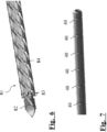
- the tools for inserting and extracting the telescopic intramedullary nail 1 into the long bone 100 of a patient are illustrated in figure 6 .
- These tools comprise a drill bit 4, a left-handed tension rod 5, an engaging sleeve 6, a right-handed tension rod 7 and a removal tool 8.
- the drill bit 4 has a cannulated stem 42 provided with a bone perforation end 41.
- a bone perforation end 41 In a spaced position with respect to the perforation end 41 there are progressive length indexes 40, whose function will be better described below. As it is better visible in figure 7 , the length indexes can be successive notches formed on the external surface of the stem 42.
- the left-handed tension rod 5 has a stem 52 provided with a threaded tip 51, in particular with a left-handed thread, at the distal end.
- This threaded tip 51 is arranged to screw into the internal thread 26 of the coupling means 25 of the hollow stem 2.
- a cylindrical handle 50 to allow the rotation of the stem 52 along its own axis.
- the right-handed tension rod 7 has a stem 72 provided with a threaded tip 71, in particular with a right-handed thread, at the distal end.
- This threaded tip 71 is arranged to screw into the expansive slot 35 of the coupling means 33 of the rod 3.
- a cylindrical handle 70 to allow the rotation of the stem 72 along its own axis.
- the handle 70 is preferably made so as to be visually and/or tactilely distinguished from the handle 50 of the left-handed tension rod.
- the two handles can be of different colours, for example the handle 50 of the left-handed tension rod 5 can be red and the handle 70 of the right-handed tension rod 7 can be green.
- the engaging sleeve 6 has a stem 62 provided at the distal end thereof with a front toothing 61, consisting in particular of two radial teeth aligned along a same diameter. Said front toothing 61 is arranged to engage into the end crenelation 27 of the coupling means 25 of the hollow stem 2; or into the diametrical groove 34 of the coupling means 33 of the rod 3. At the proximal end the engaging sleeve 6 has a cylindrical handle 60 to allow the rotation of the stem 52 along its own axis.
- the engaging sleeve 6 has a central cavity, which is not visible in the figures, to allow the rotatable housing of the stem 52 of the left-handed tension rod 5 or of the stem 72 of the right-handed tension rod 7.
- the removal tool 8 is a manual borer comprising a stem 85 and a distal boring portion 81.
- the boring portion 81 comprises a threaded tip 82, in particular with a left-handed thread, and an adjacent stem portion provided with helical grooves 84.
- the portion with helical grooves 84 frontally faces the threaded tip 82, defining a front toothing 83, consisting in particular of four equally spaced teeth, arranged to abut against the end crenelation 27 of the coupling means 25 of the hollow stem 2.
- the threaded tip 82 is instead arranged to screw into the internal thread 26 of the coupling means 25 of the hollow stem 2.
- the removal tool 8 comprises, at the proximal end, a cylindrical handle 80 to allow the rotation of the stem 82 along its own axis.
- the handle 80 is preferably made so as to be visually and/or tactilely distinguished from the handle 70 of the right-handed tension rod 7, being instead similar to the handle 50 of the left-handed tension rod 5.
- the handle 80 of the removal tool 8 can be for example red like that of the left-handed tension rod 5.
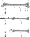
- a Kirchner wire 9 is inserted through the medullary cavity of a long bone 100 of a patient.
- the Kirchner wire is inserted up to pass the growth cartilage 101 but without entering the joint.
- the step is illustrated in figure 8 with particular reference to a femur.
- the boring step also allows an estimate of the length of the components of a telescopic intramedullary nail 1 to be used, thus avoiding the surgeon having to cut the components during the intervention.
- the boring step is illustrated in figure 9 .
- the drill bit 4 is removed keeping the Kirchner wire 9 in place, which is used to guide the hollow stem 2 in the medullary cavity.
- the hollow stem 2 is inserted by means of an insertion tool 5, 6 defined by the insertion of the left-handed tension rod 5 into the engaging sleeve 6, according to the above-described coupling modes. For the last part of the insertion the tension rod 5 is removed, continuing the insertion with the engaging sleeve 6.
- the distal anchor tip 21 is screwed down to the cancellous bone and the growth cartilage. Where the space is not enough for thread anchoring, the non-threaded anchor tip 21' described with reference to figure 2b is used. The above step of fixing the hollow stem 2 is illustrated in figure 10 .
- the rod 3 is then inserted into the hollow stem 2.
- the rod 3 is inserted by means of an insertion tool 6, 7 defined by the insertion of the right-handed tension rod 7 into the engaging sleeve 6, according to the above-described coupling modes.
- said insertion tool By means of said insertion tool the rod 3 is rotated so as to screw the conical thread 32 of the terminal head 31 into the proximal cortical of the long bone 100.
- This last step of the insertion of the telescopic intramedullary nail 1 is shown in figure 12 .
- figure 13 shows the telescopic intramedullary nail 1 engaged into the long bone 100 at the end of the described operations.
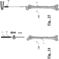
- a first step, illustrated in figure 14 the rod 3 is extracted by means of the insertion tool 6, 7 previously used for the insertion thereof.
- a boring is performed up to reach the proximal end of the hollow stem and continue the counterclockwise rotation to couple the removal tool 8 to the component and to unscrew the component from the distal epiphysis 102.
Landscapes
- Health & Medical Sciences (AREA)
- Orthopedic Medicine & Surgery (AREA)
- Surgery (AREA)
- Life Sciences & Earth Sciences (AREA)
- Heart & Thoracic Surgery (AREA)
- Nuclear Medicine, Radiotherapy & Molecular Imaging (AREA)
- Engineering & Computer Science (AREA)
- Biomedical Technology (AREA)
- Neurology (AREA)
- Medical Informatics (AREA)
- Molecular Biology (AREA)
- Animal Behavior & Ethology (AREA)
- General Health & Medical Sciences (AREA)
- Public Health (AREA)
- Veterinary Medicine (AREA)
- Surgical Instruments (AREA)
Applications Claiming Priority (1)
| Application Number | Priority Date | Filing Date | Title |
|---|---|---|---|
| IT102023000025602A IT202300025602A1 (it) | 2023-11-30 | 2023-11-30 | Chiodo telescopico e kit comprendente detto chiodo telescopico e relativo strumentario |
Publications (2)
| Publication Number | Publication Date |
|---|---|
| EP4563105A2 true EP4563105A2 (de) | 2025-06-04 |
| EP4563105A3 EP4563105A3 (de) | 2025-07-30 |
Family
ID=89898070
Family Applications (1)
| Application Number | Title | Priority Date | Filing Date |
|---|---|---|---|
| EP24216039.8A Pending EP4563105A3 (de) | 2023-11-30 | 2024-11-28 | Teleskopischer marknagel und kit mit besagtem teleskopischem marknagel und zugehörige werkzeuge |
Country Status (3)
| Country | Link |
|---|---|
| US (1) | US20250177016A1 (de) |
| EP (1) | EP4563105A3 (de) |
| IT (1) | IT202300025602A1 (de) |
Families Citing this family (3)
| Publication number | Priority date | Publication date | Assignee | Title |
|---|---|---|---|---|
| IT202300025605A1 (it) * | 2023-11-30 | 2025-05-30 | Orthofix Srl | Chiodo telescopico migliorato |
| CN121265220B (zh) * | 2025-09-28 | 2026-06-26 | 北京清兰沚科技有限公司 | 一体式磁驱动的双向髓内钉 |
| CN121533802B (zh) * | 2025-12-13 | 2026-07-17 | 中国人民解放军总医院第一医学中心 | 一种可伸缩式的髓内钉系统 |
Family Cites Families (8)
| Publication number | Priority date | Publication date | Assignee | Title |
|---|---|---|---|---|
| US8308783B2 (en) * | 2008-08-11 | 2012-11-13 | Arch Day Design, Llc | Collapsible bone screw apparatus |
| US20130041414A1 (en) * | 2010-03-10 | 2013-02-14 | Advanced Orthopaedic Solutions, Inc. | Telescoping Bone Screw |
| US20140214034A1 (en) * | 2013-01-25 | 2014-07-31 | Fady Rayes | Cannulated telescopic femoral neck screw device and related fixation method |
| US10292745B2 (en) * | 2015-10-07 | 2019-05-21 | Arthrex, Inc. | Devices for generating and applying compression within a body |
| WO2018067536A1 (en) * | 2016-10-05 | 2018-04-12 | Arthrex, Inc. | Fifth metatarsal repair systems and methods of use |
| US11478277B2 (en) * | 2020-03-11 | 2022-10-25 | DePuy Synthes Products, Inc. | Compression nut and a system for treating a bone |
| WO2023183527A1 (en) * | 2022-03-23 | 2023-09-28 | Naven Duggal | Compression systems and methods for fractures and fusions |
| EP4658191A1 (de) * | 2023-02-02 | 2025-12-10 | Segii Khmyzov | Universale pädiatrische teleskopische stange (upeter) (intarinales teleskopisches system) |
-
2023
- 2023-11-30 IT IT102023000025602A patent/IT202300025602A1/it unknown
-
2024
- 2024-11-27 US US18/962,975 patent/US20250177016A1/en active Pending
- 2024-11-28 EP EP24216039.8A patent/EP4563105A3/de active Pending
Also Published As
| Publication number | Publication date |
|---|---|
| IT202300025602A1 (it) | 2025-05-30 |
| EP4563105A3 (de) | 2025-07-30 |
| US20250177016A1 (en) | 2025-06-05 |
Similar Documents
| Publication | Publication Date | Title |
|---|---|---|
| US20250177016A1 (en) | Telescopic intramedullary nail and kit comprising said telescopic intramedullary nail and corresponding tools | |
| US20190192189A1 (en) | Bone Compression and Fixation Devices | |
| JP5931924B2 (ja) | 増強可能な転子大腿骨釘 | |
| US6524313B1 (en) | Intramedullary nail system | |
| US8128627B2 (en) | Segmented intramedullary system and apparatus | |
| US6488684B2 (en) | Intramedullary nail | |
| US8663224B2 (en) | Surgical nail | |
| US4940467A (en) | Variable length fixation device | |
| EP2083723B1 (de) | Marknagel mit stabilen sperrbolzen | |
| US11622796B2 (en) | Implant and method for long bone fixation | |
| US20120109128A1 (en) | Bone Implant | |
| EP1878394A2 (de) | Führung mit Gewinden für eine orthopädische Befestigungsplatte | |
| US20110184472A1 (en) | Expandable Bone Support | |
| KR20030062532A (ko) | 골수강내 금속정과 이의 나사삽입장치 및 나사삽입방법 | |
| JP7581344B2 (ja) | 髄内固定釘及びその使用方法 | |
| US10426529B2 (en) | Surgical systems, kits and methods for setting bone segments | |
| US12232788B2 (en) | Bone fixation system | |
| JP2024543313A (ja) | ラグスクリューおよび圧縮スクリューを備えた整形外科用固定装置 | |
| US20250195114A1 (en) | Telescopic nail and associated perforating tool | |
| US5152766A (en) | Femoral wire guide instrument | |
| WO2008064059A2 (en) | Sliding hip helical implant | |
| EP2762097B1 (de) | Modulare Verzögerungsschraube | |
| US20250176975A1 (en) | Telescopic intramedullary nail | |
| US12207855B2 (en) | Fixation device and method of using the same | |
| WO2021151151A1 (en) | Variable length bone screw |
Legal Events
| Date | Code | Title | Description |
|---|---|---|---|
| PUAI | Public reference made under article 153(3) epc to a published international application that has entered the european phase |
Free format text: ORIGINAL CODE: 0009012 |
|
| STAA | Information on the status of an ep patent application or granted ep patent |
Free format text: STATUS: THE APPLICATION HAS BEEN PUBLISHED |
|
| AK | Designated contracting states |
Kind code of ref document: A2 Designated state(s): AL AT BE BG CH CY CZ DE DK EE ES FI FR GB GR HR HU IE IS IT LI LT LU LV MC ME MK MT NL NO PL PT RO RS SE SI SK SM TR |
|
| PUAL | Search report despatched |
Free format text: ORIGINAL CODE: 0009013 |
|
| AK | Designated contracting states |
Kind code of ref document: A3 Designated state(s): AL AT BE BG CH CY CZ DE DK EE ES FI FR GB GR HR HU IE IS IT LI LT LU LV MC ME MK MT NL NO PL PT RO RS SE SI SK SM TR |
|
| RIC1 | Information provided on ipc code assigned before grant |
Ipc: A61B 17/72 20060101AFI20250626BHEP |
|
| STAA | Information on the status of an ep patent application or granted ep patent |
Free format text: STATUS: REQUEST FOR EXAMINATION WAS MADE |
|
| 17P | Request for examination filed |
Effective date: 20251230 |