EP4563250A1 - Machine de construction, ensemble de rééquipement et procédé - Google Patents
Machine de construction, ensemble de rééquipement et procédé Download PDFInfo
- Publication number
- EP4563250A1 EP4563250A1 EP24214076.2A EP24214076A EP4563250A1 EP 4563250 A1 EP4563250 A1 EP 4563250A1 EP 24214076 A EP24214076 A EP 24214076A EP 4563250 A1 EP4563250 A1 EP 4563250A1
- Authority
- EP
- European Patent Office
- Prior art keywords
- cleaning
- construction machine
- nozzle
- nozzle carrier
- support structure
- Prior art date
- Legal status (The legal status is an assumption and is not a legal conclusion. Google has not performed a legal analysis and makes no representation as to the accuracy of the status listed.)
- Pending
Links
Images




Classifications
-
- B—PERFORMING OPERATIONS; TRANSPORTING
- B08—CLEANING
- B08B—CLEANING IN GENERAL; PREVENTION OF FOULING IN GENERAL
- B08B9/00—Cleaning hollow articles by methods or apparatus specially adapted thereto
- B08B9/08—Cleaning containers, e.g. tanks
- B08B9/093—Cleaning containers, e.g. tanks by the force of jets or sprays
-
- B—PERFORMING OPERATIONS; TRANSPORTING
- B08—CLEANING
- B08B—CLEANING IN GENERAL; PREVENTION OF FOULING IN GENERAL
- B08B3/00—Cleaning by methods involving the use or presence of liquid or steam
- B08B3/02—Cleaning by the force of jets or sprays
- B08B3/024—Cleaning by means of spray elements moving over the surface to be cleaned
Definitions
- the invention relates to a construction machine for conveying thick materials.
- the invention also relates to a retrofit kit for an original construction machine for conveying thick materials.
- the invention relates to a method for a cleaning operation, in particular an automatic cleaning operation, of such a construction machine.
- the nozzle carrier can be adjusted relative to the support structure and relative to the filler opening during the formation of the liquid jet by means of its at least one nozzle device in order to spray an interior of the storage container and any components of the construction machine located between the cleaning device and the storage container with cleaning fluid in order to at least partially free the interior of the storage container or said components of adhering thick material.
- the adjustable nozzle carrier enables particularly thorough cleaning with particularly low consumption of cleaning fluid.
- control can mean “steer” and/or “regulate”.
- the nozzle carrier is adjustable relative to the support structure along a nozzle carrier adjustment direction of the cleaning device.
- the nozzle carrier adjustment direction runs transversely, in particular perpendicularly, to the nozzle carrier extension direction of the cleaning device.
- the support structure extends along the nozzle carrier extension direction and along the nozzle carrier adjustment direction, in particular in a frame-like manner. An outline of the support structure can be coordinated with an outline of the filling opening.
- the nozzle carrier adjustment direction expediently runs along a longitudinal direction of the construction machine or transversely, in particular perpendicularly, to the longitudinal direction of the construction machine.
- the positioning aids expediently engage with each other, in particular exclusively, in the cleaning position.
- the positioning aids are arranged in the cleaning position opposite a joint device of the construction machine for supporting the support structure relative to the storage container, on the storage container side and the cleaning device side, in particular on the support structure side.
- the construction machine can expediently have a locking device designed to releasably lock the cleaning device in the cleaning position relative to the storage container.
- the positioning aids can have or form the locking device.
- the construction machine has a joint device for mounting the support structure relative to the storage container, in particular in an adjustable manner.
- the cleaning device is pivotally mounted relative to the storage container about at least a first joint axis of the joint device and about a second joint axis of the joint device running perpendicular to the first joint axis.
- the joint device is mounted on the storage container side in the region of an opening corner of the filling opening and on the cleaning device side, in particular On the supporting structure side, it is connected, in particular arranged, in the area of a structural corner of the supporting structure.
- the joint device can thus connect the opening corner to the structural corner in an articulated manner.
- the joint device is designed in the manner of a universal joint.
- the support structure In the cleaning position, the support structure can be aligned substantially parallel to the filler opening and, alternatively or additionally, aligned with the filler opening.
- the second hinge axis can run horizontally in the cleaning position and substantially vertically in the non-cleaning position.
- the first hinge axis can run substantially horizontally in both the cleaning position and the non-cleaning position.
- the cleaning device comprises a drive device, in particular an electric one.
- the drive device serves for the driven adjustment of the nozzle carrier relative to the support structure.
- the cleaning device comprises a gear device, wherein the gear device serves for drivingly connecting the drive device and the nozzle carrier to one another.
- the gear device can comprise a cable pull and - alternatively or additionally - a spindle drive and - alternatively or additionally - a toothed belt drive.
- the gear device can be designed for bidirectional driving of the drive device and the nozzle carrier to one another.
- the drive device and the nozzle carrier can be drivingly connected to one another by means of the gear device in such a way that the nozzle carrier can be adjusted relative to the support structure by driving the drive device in and against the nozzle carrier adjustment direction.
- the liquid jet of cleaning liquid that can be formed by means of the at least one nozzle device of the nozzle carrier can be formed at least partially onto the grid element.
- the grid element can be sprayed with cleaning liquid for cleaning purposes during cleaning.
- the construction machine can expediently have a hydraulically arranged, in particular central, distribution valve unit upstream of the valve device through which cleaning fluid can flow.
- the distribution valve unit can be electrically controllable.
- the distribution valve unit can serve to distribute, in particular to divide, cleaning fluid between the valve device and a cleaning attachment of the construction machine for cleaning a pressure nozzle of the construction machine for discharging conveyed thick material during conveying operation.
- the storage container has a discharge opening for emptying the storage space.
- the construction machine has an openable discharge device that closes the discharge opening.
- the The construction machine has a lid that can be pivoted relative to the storage container to close the filling opening.
- the lid can either have the cleaning device, in particular as a single unit, or be designed separately from the cleaning device, in particular so as to be pivotable.
- the lid can be spring-assisted adjustable.
- the supporting structure can be spring-assisted adjustable.
- the construction machine has at least one, in particular two, conveying cylinders.
- Each conveying cylinder has a variable-volume conveying chamber for conveying thick material, wherein the conveying chamber has an outlet opening.
- the conveying chamber opens into the storage chamber at its outlet opening, in particular along the longitudinal direction of the construction machine.
- the cleaning device has nozzle devices that are non-adjustable, in particular stationary, relative to the support structure and are each designed to form a further liquid jet of cleaning liquid for the cleaning operation at least partially within the storage chamber.
- At least one of the further liquid jets that can be formed by the non-adjustable nozzle devices can be directed into the outlet opening and - alternatively or additionally - into corners of the storage chamber and - alternatively or additionally - onto a bearing device of the construction machine for the, in particular hinge-like, mounting of the thick material-permeable grid element of the construction machine.
- the at least one nozzle device of the nozzle carrier is designed as a flat jet nozzle.
- the non-adjustable nozzle devices can be designed as point jet nozzles.
- the construction machine has a sensor device designed to detect the cleaning position of the support structure.
- the construction machine has a (further) sensor device designed to detect the non-cleaning position of the support structure.
- the cleaning device has a (further) sensor device designed to detect a nozzle carrier position of the nozzle carrier relative to the support structure, in particular wherein the nozzle carrier is monitored for end positions by means of this sensor device.
- the construction machine has a (further) sensor device designed to detect an open state of the openable emptying device of the construction machine that closes the emptying opening of the storage container.
- Such sensor devices can enable particularly reliable cleaning and/or conveying operation of the construction machine.
- the construction machine has a pipe switch, in particular an S-shaped one.
- the pipe switch defines a control channel of the construction machine on the inside.
- the control channel is fluidly connected at one end to the pressure nozzle of the construction machine for discharging the conveyed thick material during conveying operation.
- the pipe switch in particular within the storage chamber, is adjustable relative to the at least one conveying chamber of the construction machine such that the at least one conveying chamber can be fluidly connected alternately to the pressure nozzle and, in particular directly, to the storage chamber by means of the control channel.
- the construction machine has a cleaning attachment that can be coupled to the pressure nozzle for cleaning the pressure nozzle with cleaning fluid.
- the construction machine has a (different) sensor device designed to detect a coupled state of the cleaning attachment and the pressure nozzle.
- the cleaning attachment advantageously enables the cleaning of areas of the construction machine that are exposed to thick material during conveying operation and that cannot be directly sprayed with cleaning fluid using the cleaning device.
- a retrofit kit according to the invention is provided for a base construction machine for conveying thick material.
- the base construction machine has a storage space for storing the thick material to be conveyed for a conveying operation of the base construction machine and a storage container which partially delimits the storage space on the inside, in particular with its container interior, wherein the storage container has a filling opening for filling the thick material to be stored into the storage space.
- the base construction machine differs from the construction machine according to the invention at least in that the base construction machine does not have a cleaning device with a supporting structure and adjustable nozzle carrier.
- the base construction machine can be converted into a
- the retrofit kit according to the invention can be retrofitted as described above.
- the retrofit kit according to the invention can enable the above-described advantages of the construction machine according to the invention to be achieved.
- the retrofit kit comprises the cleaning device through which a cleaning fluid can flow for cleaning the retrofitted construction machine.
- the retrofit kit also comprises a cleaning attachment designed to clean a pressure port of the original construction machine for discharging the high-density material conveyed during conveying operation.
- a method according to the invention serves for a cleaning operation, in particular an automatic one, of a construction machine according to the invention according to the above description.
- the method according to the invention can enable the utilization of the above-described advantages of the construction machine according to the invention.
- the method comprises a step a), according to which a check is carried out to determine whether the support structure is in the cleaning position.
- the check according to step a) is carried out by corresponding detection, i.e., in particular detection corresponding to the object to be checked, using a sensor device of the construction machine.
- the method comprises a step b), according to which - only if step a) shows that the support structure is in the cleaning position - the cleaning operation is activated.
- the cleaning operation according to step b) is activated after an activating user input.
- the method further comprises a step c), according to which the cleaning operation is carried out.
- the cleaning operation comprises a step a), according to which the at least one nozzle device of the nozzle carrier is supplied with cleaning fluid.
- the application according to step A) takes place in order, in particular for each nozzle device, to form a liquid jet of cleaning liquid onto a thick-matter-permeable grid element of the construction machine that covers the inlet opening in a manner permeable to thick matter.
- an adjustment of the nozzle carrier relative to the support structure takes place, in particular simultaneously with the application.
- the nozzle carrier is adjusted relative to the support structure in order to spray the thick-matter-permeable grid element with cleaning liquid while sweeping it over it.
- the nozzle carrier can therefore be adjusted relative to the support structure simultaneously according to step A) during the formation of the liquid jet by means of the at least one nozzle device, so that the thick-matter-permeable grid element is swept over by the formed liquid jet.
- the nozzle carrier is expediently adjusted from a first end position of the nozzle carrier via a second end position of the nozzle carrier opposite the first end position in the nozzle carrier adjustment direction and back to the first end position while its at least one nozzle device is being supplied with cleaning liquid.
- the grid element can thus be swept twice, in particular substantially over its entire surface, by the nozzle carrier or the liquid jet formed by the at least one nozzle device along the nozzle carrier adjustment direction.
- a drive device of the cleaning device can be automatically switched over for the driven adjustment of the nozzle carrier relative to the support structure in order to reverse a drive direction of the drive device. Accordingly, the nozzle carrier can be automatically moved back and forth between its end positions.
- step c) additional non-adjustable, particularly stationary, nozzle devices of the cleaning device can expediently be operated.
- the nozzle devices can be operated prior to the nozzle devices to enable pre-cleaning before the operation of the nozzle devices according to step A).
- step a) it is also checked whether the cleaning attachment is coupled to the pressure nozzle and whether the emptying device is open, in particular by corresponding detection, i.e. in particular corresponding to the object to be checked, using further sensor devices of the construction machine.
- the cleaning operation is only activated, in particular after an activating user input, if it also results from step a) that the cleaning attachment is coupled and the emptying device is open.
- the activating user input can be made by manually pressing an activation switch of the construction machine.
- the cleaning operation carried out according to step c) further comprises a step A1), according to which the cleaning attachment is pressurized with cleaning fluid in order to clean the pressure nozzle and the control channel and the at least one conveying chamber, in particular wherein the pipe switch is adjusted while varying the volume of the at least one conveying chamber.
- the cleaning operation carried out according to step c) also comprises a step A2), according to which the non-adjustable nozzle devices are jointly or selectively supplied with cleaning fluid in order to form, by means of the acted-on non-adjustable nozzle devices, liquid jets jointly or selectively into the outlet opening and - alternatively or additionally - into corners of the storage space and - alternatively or additionally - onto the storage device of the construction machine for storing the thick-material-permeable grid element of the construction machine.
- steps of the method are expediently carried out in the chronological order a), b), c), with the steps of the cleaning operation being carried out in the chronological order A1), A2), A).
- steps A2) and A) may be repeated at least once or more often.
- the construction machine can be operated in its conveying mode during the concreting operation.
- the non-adjustable nozzle devices can expediently be operated in groups according to step A2) of the cleaning operation. For example, a first group of non-adjustable nozzle devices can first be subjected to a cleaning fluid pressure of 16 bar for a time interval of 10 s. A second group of non-adjustable nozzle devices can then be subjected to cleaning fluid, in particular to a cleaning fluid pressure of 16 bar, for a further time interval of 10 s. After the pre-cleaning has been carried out using the non-adjustable nozzle devices, the nozzle devices of the nozzle carrier can then and/or finally be subjected to cleaning fluid according to step A) of the cleaning operation, while the nozzle carrier is adjusted relative to the support structure.
- a construction machine 1 according to the invention is intended for conveying thick material.
- the thick material can be a building material.
- the thick material can be a paste-like mixture of different materials.
- the thick material can be mortar, cement, screed, or concrete, each in a mixable and/or conveyable state. In the mixable and/or conveyable state, the thick material has not yet hardened or set.
- the construction machine 1 has a storage container 3.
- the storage container 3 defines a storage chamber 2 of the construction machine 1 on the inside.
- the storage chamber 2 serves to store thick material to be conveyed for a conveying operation of the construction machine 1.
- the storage container 3 has a filling opening 4.
- the filling opening 4 serves to fill the thick material to be stored into the storage chamber 2.
- the thick material stored in the storage chamber 2 can be conveyed.
- the thick material can be discharged through a pressure nozzle 25 of the construction machine 1 during conveying operation of the construction machine 1.
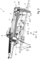
- the construction machine 1 has a cleaning device 5 through which cleaning fluid can flow.
- the cleaning device 5 allows the cleaning fluid to flow through it for cleaning the construction machine 1.
- the cleaning operation is carried out, in particular, after concreting has been completed by means of the conveying operation of the construction machine 1.
- the cleaning fluid can be fresh water, process water, or a mixture of fresh water and process water.
- the cleaning device 5 has a support structure 6, which is configured for positioning at the filling opening 4. Furthermore, the cleaning device 5 has a nozzle carrier 7. The nozzle carrier 7 is adjustable relative to the support structure 6. The nozzle carrier 7 has at least one nozzle device 8 for forming a liquid jet of cleaning fluid for the cleaning operation.
- the nozzle carrier 7 has a plurality of nozzle devices 8, each of which is designed to form a liquid jet for cleaning operation.
- the nozzle carrier 7 is, for example, longitudinally extended along a nozzle carrier extension direction DE of the cleaning device 5.
- the nozzle carrier 7 is tubular and bar-shaped.
- the tubular nozzle carrier 7 in this case can be flowed through, for example, by cleaning liquid for the liquid jets.
- the nozzle devices 8 of the nozzle carrier 7 are arranged at a distance from one another, for example, along the nozzle carrier extension direction DE.
- the nozzle devices 8 can be arranged at a distance from one another transversely to the nozzle carrier extension direction DE.
- the nozzle carrier 7 is adjustable relative to the support structure 6, for example, along a nozzle carrier adjustment direction DV of the cleaning device 5.
- the nozzle carrier adjustment direction DV runs perpendicular to the nozzle carrier extension direction DE of the cleaning device 5.
- the support structure 6 extends, for example, along the nozzle support extension direction DE and along the nozzle support adjustment direction DV.
- the support structure 6 extends in a frame-like manner along the nozzle support extension direction DE and along the nozzle support adjustment direction DV.
- the frame-shaped support structure 6 comprises, for example, blanks of linearly extending, in particular identical, aluminum extruded profiles.
- the at least one nozzle device 8 is designed, for example, to form a liquid jet of cleaning liquid at an exit angle relative to a cleaning direction RR of the cleaning device 5, which extends perpendicular to the nozzle carrier extension direction DE and perpendicular to the nozzle carrier adjustment direction DV.
- the exit angle can be 0° to 90°, in particular 10° to 20°. In the present case, the exit angle is 15°.
- the cleaning direction RR is set, for example, at an angle of 5° to 15°, in the present case approximately 10°, relative to the direction of gravity.
- the nozzle carrier 7 can be linearly adjustable relative to the support structure 6 along the nozzle carrier adjustment direction DV.
- the nozzle carrier 7 can be movably guided on the support structure 6.
- the support structure 6 can have a slotted guide 10 by means of which the nozzle carrier 7 is guided.
- the slotted guide 10 can have elastic sealing strips 9 designed to keep thick material away from a slotted groove of the slotted guide 10.
- the slotted groove can be formed by an extruded aluminum profile section of the support structure 6.
- the nozzle carrier 7 has a plurality of nozzle pairs 11.
- a nozzle pair 11 is formed, for example, by two nozzle devices 8 of the nozzle carrier 7 that are directly adjacent along the nozzle carrier extension direction DE.
- one of the nozzle devices 8 of the nozzle pair 11 is designed to form a liquid jet of cleaning liquid in the nozzle carrier adjustment direction DV.
- the other nozzle device 8 of the nozzle pair 11 is designed to form a different liquid jet of cleaning liquid opposite to the nozzle carrier adjustment direction DV.
- a nozzle spacing between the nozzle devices 8 of the nozzle pair 11 along the nozzle carrier extension direction DE can be smaller than a nozzle pair spacing between directly adjacent nozzle pairs 11 along the nozzle carrier extension direction DE.
- the nozzle pair 11 can be supplemented by further nozzle devices 8 in order to form a nozzle group of the nozzle carrier 7 comprising the nozzle pair 11. Between nozzle devices 8 of such a nozzle group, there can be a smaller nozzle spacing than a nozzle group spacing existing between such nozzle groups.
- the support structure 6 is adjustable relative to the storage container 3 between a cleaning position PR for cleaning operation and a non-cleaning position PN for non-cleaning operation of the construction machine 1.
- the cleaning position PR In this case, the support structure 6 is arranged at the filling opening 4.
- the non-cleaning position PN the filling opening 4 can be exposed by means of the support structure 6.
- the nozzle carrier 7 is adjustable relative to the support structure 6, for example, at least or exclusively in the cleaning position PR.
- the nozzle carrier adjustment direction DV can—as in the present case—extend along a construction machine longitudinal extension direction of the construction machine 1.
- the nozzle carrier adjustment direction DV can extend transversely, in particular perpendicularly, to the construction machine longitudinal extension direction.
- the storage container 3 and the cleaning device 5 have complementary positioning aids 16, which are designed to position the cleaning device 5 in the cleaning position PR.
- the positioning aids 16 can be designed to be low-friction.
- the construction machine 1 can have a locking device, by means of which the support structure 6 can be releasably held on the storage container 3 in the cleaning position PR.
- the locking device can be formed by the positioning aids 16 or can be provided by the positioning aids 16.
- the positioning aids 16 engage with one another in the cleaning position PR.
- the positioning aids 16 can each be located on the storage container side and the cleaning device side, in particular on the support structure side, opposite an articulated device 12 of the construction machine 1 for mounting the support structure 6 relative to the storage container 3.
- the cleaning device 5 is pivotally mounted relative to the storage container 3 about a first joint axis G1 of the joint device 12 and about a second joint axis G2 of the joint device 12, which extends perpendicular to the first joint axis G1.
- the joint device 12 can have further joint axes.
- the joint device 12 is arranged on the storage container side in the region of an opening corner 13 of the filling opening 4.
- the joint device 12 can be arranged in the region of a structural corner 14 of the support structure 6.
- the opening corner 13 and the structural corner 14 are in this case pivotally connected to one another by means of the joint device 12.
- the joint device 12 can be connected to the storage container 3 in the region of the opening corner 13. In the area of the structural corner 14, the joint device 12 can be connected to the cleaning device 5.
- the cleaning device 5 in the non-cleaning position PN, can be arranged along a substantially vertical lateral flank side 15 of the construction machine 1.
- the flank side 15 extends along the longitudinal extension direction of the construction machine and along the direction of gravity.
- the cleaning device 5 In the non-cleaning position PN, the cleaning device 5 can be aligned along the flank side 15.
- the cleaning device 5 In the non-cleaning position PN, the cleaning device 5 can be pivoted away from the filling opening 4 both about the first joint axis G1 and about the second joint axis G2.
- the first joint axis G1 can run along the nozzle carrier extension direction DE.
- the support structure 6 is first pivoted about the first joint axis G1 and then about the second joint axis G2 in order to move the support structure 6 from the cleaning position PR to the non-cleaning position PN.
- the reverse procedure can be used to move the support structure 6 back from the non-cleaning position PN to the cleaning position PR.
- the cleaning direction RR of the cleaning device 5 can point away from the flank side 15 of the construction machine 1, for example horizontally.
- the support structure 6 can be aligned substantially parallel to the filling opening 4 and—alternatively or additionally—aligned with the filling opening 4.
- Fig. 4 The two joint axes G1, G2 are shown with the cleaning device 5 in the cleaning position PR.
- the second joint axis G2 can be pivoted on a Fig. 2
- the cleaning device 5 has, for example, a drive device 17, in particular an electric one.
- the drive device 17 is designed for the driven adjustment of the nozzle carrier 7 relative to the support structure 6.
- the nozzle carrier 7 can thus be adjusted relative to the support structure 6.
- the cleaning device 5 has a gear device 18.
- the gear device 18 has a cable pull 19.
- the gear device 18 can have a spindle drive.
- the gear device 18 can have a toothed belt drive.
- the drive device 17 and the nozzle carrier 7 are bidirectionally connected to one another by means of the gear device 18. Accordingly, the nozzle carrier 7 can be moved by means of the drive device 17 in the nozzle carrier adjustment direction DV and opposite to the nozzle carrier adjustment direction DV relative to the support structure 6.
- the construction machine 1 has a slurry-permeable grid element 20.
- the slurry-permeable grid element 20 serves to cover the filling opening 4 in a way that allows slurry to pass through it when filling the slurry to be stored into the storage space 2.
- the grid element 20 can serve to screen the slurry.
- the grid element 20 has an overlapping position PU for filling the thick material into the storage space 2 through the grid element 20.
- the filling opening 4 can be at least partially covered by the grid element 20.
- the grid element 20 is adjustable relative to the storage container 3 from the overlapping position PU in order to expose the filling opening 4.
- the grid element 20 can be pivoted upwards away from the storage container 3 from the overlapping position PU.
- the liquid jet of cleaning liquid that can be formed by means of the at least one nozzle device 8 of the nozzle carrier 7 can be formed at least partially onto the grid element 20 when the support structure 6 is in the cleaning position PR and the grid element 20 is in the overlapping position PU.
- the construction machine 1 has a valve device 21 for controlling the distribution of cleaning fluid.
- the valve device 21 is a component of the cleaning device 5.
- the valve device 21 can be electrically controllable.
- the construction machine 1 has, for example, at least two—in this case, exactly two—fluid line sections 22, 23 through which cleaning fluid can flow.
- the valve device 21 can be designed to control the distribution of cleaning fluid between the fluid line sections 22, 23.
- One of the fluid line sections 22 is designed in this case to supply cleaning fluid to the at least one nozzle device 8 of the nozzle carrier 7.
- Another of the fluid line sections 23 can be designed to supply cleaning fluid to at least one non-adjustable, in particular stationary, nozzle device 31 of the cleaning device 5.
- the construction machine 1 can have a distribution valve unit, in particular a central one, upstream of the valve device 21.
- the distribution valve unit can be designed to distribute cleaning fluid between the valve device 21 and a cleaning attachment 24 of the construction machine 1 for cleaning the pressure port 25 of the construction machine 1.
- the storage container 3 has a discharge opening 26 for emptying the storage space 2.
- the discharge opening 26 can be arranged opposite the filling opening 4 along the direction of gravity.
- the construction machine 1 has an openable discharge device 27 that closes the discharge opening 26.
- the construction machine 1 has a lid 28 for closing the filling opening 4.
- the lid 28 can be pivotable relative to the storage container 3.
- the lid 28 and the cleaning device 5 are formed separately from one another and can be pivoted separately from one another relative to the storage container 3.
- the lid 28 can comprise the cleaning device 5, in particular as a single unit.
- the cleaning device 5 can at least partially cover the filling opening 4 in the cleaning position PR in a transparent manner and - alternatively or additionally - in a fluid-permeable manner.
- the filling opening 4 can, in contrast, be closed in the cleaning position PR, in particular by means of the cover 28 and - alternatively or additionally - the cleaning device 5, in an opaque manner and - alternatively or additionally - at least in a thick-matter-tight manner.
- the support structure 6 of the cleaning device 5 can be fastened to the cover 28, so that the cover 28 and the cleaning device 5 can only be adjusted jointly relative to the storage container 3.
- the lid 28 can be spring-assisted and adjustable relative to the storage container 3.
- the support structure 6 can be spring-assisted and adjustable relative to the storage container 3.
- the construction machine 1 has at least one—in this case, exactly two—conveying cylinders C1, C2.
- Each of the conveying cylinders C1, C2 has a variable-volume conveying chamber 29 for conveying thick material.
- the conveying chambers 29 each have an outlet opening 30.
- the conveying chambers 29 each open into the storage chamber 2 at their outlet openings 30.
- the cleaning device 5 has nozzle devices 31 that are non-adjustable relative to the support structure 6.
- Such non-adjustable nozzle devices 31 can also be referred to as stationary nozzle devices 31.
- the non-adjustable nozzle devices 31 are each designed to form a further liquid jet of cleaning liquid for the cleaning operation at least partially within the Storage space 2.
- At least one of the further liquid jets that can be formed by the non-adjustable nozzle devices 31 can be formed into the mouth opening 30 of one of the conveying spaces 29.
- at least one of the further liquid jets that can be formed by the non-adjustable nozzle devices 31 can be formed into a corner 32 of the storage space 2.
- At least one of the further liquid jets that can be formed by the non-adjustable nozzle devices 31 can be formed onto a, in particular hinge-like, bearing device 33 of the construction machine 1 for supporting the thick-material-permeable grid element 20 of the construction machine 1.
- the at least one nozzle device 8 in this case, all of the nozzle devices 8—of the nozzle carrier 7 can be designed as a flat jet nozzle 34.
- the non-adjustable nozzle devices 31 as in the present case—can be designed as point jet nozzles 35.
- the construction machine 1 has, for example, a pipe switch 37, which in this case is S-shaped.
- the pipe switch 37 delimits on the inside a control channel 38 of the construction machine 1 for the thick material to be conveyed to flow through.
- the control channel 38 is fluidly connected at a first of its ends to the pressure nozzle 25 of the construction machine 1.
- the pipe switch 37 can be adjustable relative to the at least one conveying chamber 29, in particular within the storage chamber 2, so that the at least one conveying chamber 29 can be fluidly connected alternately by means of the control channel 38 to the pressure nozzle 25 and, in particular directly, to the storage chamber 2.
- the two conveying chambers 29 can be fluidly connected alternately to the pressure nozzle 25 and the storage chamber 2 by means of the control channel 38.
- the construction machine 1 has a cleaning attachment 24 for cleaning the pressure port 25 with cleaning fluid.
- the cleaning attachment 24 can be coupled, in particular detachably, to the pressure port 25.
- the construction machine 1 can have another sensor device 36 configured to detect a coupled state of the cleaning attachment 24 and the pressure port 25.
- the construction machine 1 is based on a basic construction machine for conveying thick material.
- the basic construction machine has the storage space 2 for storing the thick material to be conveyed for conveying operation.
- the basic construction machine has the storage container 3, which delimits the storage space 2 on the inside.
- the storage container 3 of the basic construction machine can have the filling opening 4 for filling the thick material to be stored into the storage space 2.
- the basic construction machine is converted by means of a retrofit kit 50 according to the invention to the Fig. 1 to 3 retrofitted to the construction machine 1 shown.
- the cleaning device 5 through which the cleaning fluid can flow is presently a component of the retrofit kit 50.
- the cleaning device 5 of the retrofit kit 50 can be provided for cleaning operation of the retrofitted construction machine 1.
- the retrofit kit 50 can have the cleaning attachment 24, which is designed to clean the pressure nozzle 25 of the original construction machine for discharging conveyed thick material during conveying operation.
- the cleaning operation of the construction machine 1 can be carried out according to a method V according to the invention.
- the method V makes it possible, for example, to carry out the cleaning operation of the construction machine 1 automatically.
- the method V comprises a step a), according to which it is checked whether the support structure 6 is in the cleaning position PR.
- the checking of the cleaning position PR according to step a) can be carried out by corresponding detection using the relevant sensor device 36 of the construction machine 1.
- the method V also comprises a step b), according to which the cleaning operation is activated exclusively if step a) shows that the support structure 6 is in the cleaning position PR.
- the activation of the cleaning operation according to step b) can only take place if an activating user input has previously been made.
- Method V further comprises a step c), according to which the cleaning operation is carried out, in particular automatically.
- the cleaning operation comprises a step A).
- the at least one nozzle device 8 of the nozzle carrier 7 is supplied with cleaning fluid in order to form a liquid jet of cleaning fluid onto the thick-matter-permeable grid element 20 covering the inlet opening 4 in a manner permeable to thick matter.
- all nozzle devices 8 of the nozzle carrier 7 are supplied with cleaning fluid simultaneously according to step A), in order to form a liquid jet of cleaning fluid for each nozzle device 8 onto the thick-matter-permeable grid element 20 covering the inlet opening 4 in a manner permeable to thick matter.
- the nozzle carrier 7 is also adjusted relative to the support structure 6.
- the at least one nozzle device 8 is exposed to cleaning fluid simultaneously with the adjustment of the nozzle carrier 7 relative to the support structure 6.
- the thick-material-permeable grid element 20 can be blasted with cleaning fluid by exposing the nozzle devices 8 to cleaning fluid while the nozzle carrier 7 is simultaneously adjusted relative to the support structure 6.
- the nozzle carrier 7 is adjusted from a first end position E1 of the nozzle carrier 7 while its at least one nozzle device 8 is being supplied with cleaning fluid, via a second end position E2 of the nozzle carrier 7 opposite the first end position E1 in the nozzle carrier adjustment direction DV, and back to the first end position E1.
- the grid element 20 can be swept over twice, in particular substantially over its entire surface, by the nozzle carrier 7 or the liquid jet formed by the at least one nozzle device 8 along the nozzle carrier adjustment direction DV.
- step a) of method V it can be checked whether the cleaning attachment 24 is coupled to the pressure nozzle 25, for example by corresponding detection by means of one of the further sensor devices 36 of the construction machine 1 set up for this purpose.
- step a) it can also be checked whether the emptying device 27 is open, for example by corresponding detection by means of one of the further sensor devices 36 set up for this purpose.
- step b) the cleaning operation can only be activated if step a) shows that the cleaning attachment 24 is coupled and - alternatively or additionally - the emptying device 27 is open.
- the cleaning operation performed according to step c) may include a step A1).
- the cleaning attachment 24 is pressurized with cleaning fluid to clean the pressure port 25 and the control channel 38 and the at least one conveying chamber 29.
- the pipe switch 37 can be adjusted, varying the volume of the at least one conveying chamber 29.
- the cleaning operation performed according to step c) comprises a step A2).
- the non-adjustable nozzle devices 31 are jointly or selectively supplied with cleaning fluid.
- liquid jets can be formed jointly or selectively into the outlet opening 30 and—alternatively or additionally—into corners 32 of the storage space 2 and—alternatively or additionally—onto the bearing device 33 of the construction machine 1 by means of the supplied non-adjustable nozzle devices 31.
- steps of method V are performed in the chronological order a), b), c), with the steps of the cleaning operation according to step c) being performed in the chronological order A1), A2), A).
- steps A2) and A) of the cleaning operation can each be repeated at least once or more often.
Landscapes
- Engineering & Computer Science (AREA)
- Mechanical Engineering (AREA)
- Cleaning By Liquid Or Steam (AREA)
Applications Claiming Priority (1)
| Application Number | Priority Date | Filing Date | Title |
|---|---|---|---|
| DE102023132552.3A DE102023132552A1 (de) | 2023-11-22 | 2023-11-22 | Baumaschine, Nachrüstset und Verfahren |
Publications (1)
| Publication Number | Publication Date |
|---|---|
| EP4563250A1 true EP4563250A1 (fr) | 2025-06-04 |
Family
ID=93607846
Family Applications (1)
| Application Number | Title | Priority Date | Filing Date |
|---|---|---|---|
| EP24214076.2A Pending EP4563250A1 (fr) | 2023-11-22 | 2024-11-20 | Machine de construction, ensemble de rééquipement et procédé |
Country Status (2)
| Country | Link |
|---|---|
| EP (1) | EP4563250A1 (fr) |
| DE (1) | DE102023132552A1 (fr) |
Citations (4)
| Publication number | Priority date | Publication date | Assignee | Title |
|---|---|---|---|---|
| JPH0484662U (fr) * | 1990-11-30 | 1992-07-23 | ||
| DE4208831A1 (de) * | 1992-03-19 | 1993-09-23 | Putzmeister Maschf | Autobetonpumpe |
| CN217734883U (zh) * | 2022-01-13 | 2022-11-04 | 齐河县城乾建材有限公司 | 一种细石混凝土灌浆机 |
| CN219175890U (zh) * | 2023-02-13 | 2023-06-13 | 三一汽车制造有限公司 | 料斗盖、料斗和泵送设备 |
Family Cites Families (1)
| Publication number | Priority date | Publication date | Assignee | Title |
|---|---|---|---|---|
| DE2713136A1 (de) * | 1977-03-25 | 1978-10-05 | Stetter Gmbh | Vorrichtung zum lagern und foerdern von beton und anderen breiigen massen |
-
2023
- 2023-11-22 DE DE102023132552.3A patent/DE102023132552A1/de active Pending
-
2024
- 2024-11-20 EP EP24214076.2A patent/EP4563250A1/fr active Pending
Patent Citations (4)
| Publication number | Priority date | Publication date | Assignee | Title |
|---|---|---|---|---|
| JPH0484662U (fr) * | 1990-11-30 | 1992-07-23 | ||
| DE4208831A1 (de) * | 1992-03-19 | 1993-09-23 | Putzmeister Maschf | Autobetonpumpe |
| CN217734883U (zh) * | 2022-01-13 | 2022-11-04 | 齐河县城乾建材有限公司 | 一种细石混凝土灌浆机 |
| CN219175890U (zh) * | 2023-02-13 | 2023-06-13 | 三一汽车制造有限公司 | 料斗盖、料斗和泵送设备 |
Also Published As
| Publication number | Publication date |
|---|---|
| DE102023132552A1 (de) | 2025-05-22 |
Similar Documents
| Publication | Publication Date | Title |
|---|---|---|
| CH667529A5 (de) | Vorrichtung zum dosierten abfuellen von fliessfaehigem fuellgut in behaelter. | |
| DE1436287A1 (de) | Verfahren zum Filtern eines Fluids und Anlage zur Durchfuehrung des Verfahrens | |
| DE1901149A1 (de) | Filterspuelgeraet | |
| DE9017025U1 (de) | Fahrbare Vorrichtung zum Reinigen von Bodenbelägen | |
| EP4563250A1 (fr) | Machine de construction, ensemble de rééquipement et procédé | |
| WO2018065079A1 (fr) | Machine et procédé de nettoyage du ballast sur une voie ferrée | |
| DE2636283C2 (de) | Einrichtung zum Reinigen der Türen von Verkokungsöfen | |
| EP1654967B1 (fr) | Groupe d'infusion pour une machine à café | |
| EP0307699A2 (fr) | Dispositif de concentration à disques | |
| DE3634137A1 (de) | Verfahren und vorrichtung zum diskontinuierlichen aufbringen eines aushaertenden stoffes auf einen gegenstand | |
| DE4105109C2 (de) | Selbstreinigender Filter für Flüssigkeiten | |
| EP0334140B1 (fr) | Machine à café munie d'une chambre d'infusion | |
| DE3135657C2 (de) | Maschine zum Fördern und Spritzen von Materialmischungen verschiedenster Viskosität und Körnungen | |
| DE1461512A1 (de) | Filterpresse | |
| DE102016100597B4 (de) | Vorrichtung und Verfahren zum Reinigen von Pinseln | |
| DE19727762C2 (de) | Vorrichtung zum Entwässern von Schlamm und ähnlichen Substanzen | |
| DE19847713A1 (de) | Kleberauftrags- und Wartungsvorrichtung | |
| DE10303817B4 (de) | Filterplatte | |
| DE2256980A1 (de) | Verfahren und vorrichtung zum filtrieren und zur weiterbehandlung des filterkuchens | |
| DE2142722A1 (de) | Pump- und Förderapparat für dichte Flüssigkeitsmischungen, wie Beton oder dgl | |
| DE1517847A1 (de) | Bodenverschluss fuer Laeuterbottiche | |
| EP4357556A1 (fr) | Machine de construction, ensemble de rééquipement et procédé | |
| WO2014121405A1 (fr) | Malaxeur servant à la production de béton et procédé pour le faire fonctionner | |
| DE3340067C2 (de) | Abdichteinrichtung für die Planieröffnung an einer Horizontalkammer einer Koksofenbatterie | |
| DE3633111A1 (de) | Vorrichtung zum reinigen von grossflaechigen textilauflagen, insbesondere von teppichboeden |
Legal Events
| Date | Code | Title | Description |
|---|---|---|---|
| PUAI | Public reference made under article 153(3) epc to a published international application that has entered the european phase |
Free format text: ORIGINAL CODE: 0009012 |
|
| STAA | Information on the status of an ep patent application or granted ep patent |
Free format text: STATUS: THE APPLICATION HAS BEEN PUBLISHED |
|
| AK | Designated contracting states |
Kind code of ref document: A1 Designated state(s): AL AT BE BG CH CY CZ DE DK EE ES FI FR GB GR HR HU IE IS IT LI LT LU LV MC ME MK MT NL NO PL PT RO RS SE SI SK SM TR |
|
| STAA | Information on the status of an ep patent application or granted ep patent |
Free format text: STATUS: REQUEST FOR EXAMINATION WAS MADE |
|
| 17P | Request for examination filed |
Effective date: 20250811 |