EP4563336A1 - Dispositif de transport - Google Patents
Dispositif de transport Download PDFInfo
- Publication number
- EP4563336A1 EP4563336A1 EP23213603.6A EP23213603A EP4563336A1 EP 4563336 A1 EP4563336 A1 EP 4563336A1 EP 23213603 A EP23213603 A EP 23213603A EP 4563336 A1 EP4563336 A1 EP 4563336A1
- Authority
- EP
- European Patent Office
- Prior art keywords
- yoke
- rotation
- transport device
- drive motor
- shaft
- Prior art date
- Legal status (The legal status is an assumption and is not a legal conclusion. Google has not performed a legal analysis and makes no representation as to the accuracy of the status listed.)
- Pending
Links
Images






Classifications
-
- B—PERFORMING OPERATIONS; TRANSPORTING
- B29—WORKING OF PLASTICS; WORKING OF SUBSTANCES IN A PLASTIC STATE IN GENERAL
- B29C—SHAPING OR JOINING OF PLASTICS; SHAPING OF MATERIAL IN A PLASTIC STATE, NOT OTHERWISE PROVIDED FOR; AFTER-TREATMENT OF THE SHAPED PRODUCTS, e.g. REPAIRING
- B29C70/00—Shaping composites, i.e. plastics material comprising reinforcements, fillers or preformed parts, e.g. inserts
- B29C70/04—Shaping composites, i.e. plastics material comprising reinforcements, fillers or preformed parts, e.g. inserts comprising reinforcements only, e.g. self-reinforcing plastics
- B29C70/28—Shaping operations therefor
- B29C70/54—Component parts, details or accessories; Auxiliary operations, e.g. feeding or storage of prepregs or SMC after impregnation or during ageing
-
- B—PERFORMING OPERATIONS; TRANSPORTING
- B29—WORKING OF PLASTICS; WORKING OF SUBSTANCES IN A PLASTIC STATE IN GENERAL
- B29C—SHAPING OR JOINING OF PLASTICS; SHAPING OF MATERIAL IN A PLASTIC STATE, NOT OTHERWISE PROVIDED FOR; AFTER-TREATMENT OF THE SHAPED PRODUCTS, e.g. REPAIRING
- B29C31/00—Handling, e.g. feeding of the material to be shaped, storage of plastics material before moulding; Automation, i.e. automated handling lines in plastics processing plants, e.g. using manipulators or robots
- B29C31/04—Feeding of the material to be moulded, e.g. into a mould cavity
- B29C31/08—Feeding of the material to be moulded, e.g. into a mould cavity of preforms to be moulded, e.g. tablets, fibre reinforced preforms, extruded ribbons, tubes or profiles; Manipulating means specially adapted for feeding preforms, e.g. supports conveyors
-
- B—PERFORMING OPERATIONS; TRANSPORTING
- B29—WORKING OF PLASTICS; WORKING OF SUBSTANCES IN A PLASTIC STATE IN GENERAL
- B29D—PRODUCING PARTICULAR ARTICLES FROM PLASTICS OR FROM SUBSTANCES IN A PLASTIC STATE
- B29D99/00—Subject matter not provided for in other groups of this subclass
- B29D99/0025—Producing blades or the like, e.g. blades for turbines, propellers, or wings
-
- B—PERFORMING OPERATIONS; TRANSPORTING
- B65—CONVEYING; PACKING; STORING; HANDLING THIN OR FILAMENTARY MATERIAL
- B65G—TRANSPORT OR STORAGE DEVICES, e.g. CONVEYORS FOR LOADING OR TIPPING, SHOP CONVEYOR SYSTEMS OR PNEUMATIC TUBE CONVEYORS
- B65G47/00—Article or material-handling devices associated with conveyors; Methods employing such devices
- B65G47/74—Feeding, transfer, or discharging devices of particular kinds or types
- B65G47/90—Devices for picking-up and depositing articles or materials
- B65G47/91—Devices for picking-up and depositing articles or materials incorporating pneumatic, e.g. suction, grippers
-
- B—PERFORMING OPERATIONS; TRANSPORTING
- B65—CONVEYING; PACKING; STORING; HANDLING THIN OR FILAMENTARY MATERIAL
- B65G—TRANSPORT OR STORAGE DEVICES, e.g. CONVEYORS FOR LOADING OR TIPPING, SHOP CONVEYOR SYSTEMS OR PNEUMATIC TUBE CONVEYORS
- B65G47/00—Article or material-handling devices associated with conveyors; Methods employing such devices
- B65G47/74—Feeding, transfer, or discharging devices of particular kinds or types
- B65G47/90—Devices for picking-up and depositing articles or materials
- B65G47/91—Devices for picking-up and depositing articles or materials incorporating pneumatic, e.g. suction, grippers
- B65G47/914—Devices for picking-up and depositing articles or materials incorporating pneumatic, e.g. suction, grippers provided with drive systems incorporating rotary and rectilinear movements
-
- B—PERFORMING OPERATIONS; TRANSPORTING
- B66—HOISTING; LIFTING; HAULING
- B66C—CRANES; LOAD-ENGAGING ELEMENTS OR DEVICES FOR CRANES, CAPSTANS, WINCHES, OR TACKLES
- B66C1/00—Load-engaging elements or devices attached to lifting or lowering gear of cranes or adapted for connection therewith for transmitting lifting forces to articles or groups of articles
- B66C1/02—Load-engaging elements or devices attached to lifting or lowering gear of cranes or adapted for connection therewith for transmitting lifting forces to articles or groups of articles by suction means
- B66C1/0237—Multiple lifting units; More than one suction area
- B66C1/0243—Separate cups
-
- B—PERFORMING OPERATIONS; TRANSPORTING
- B66—HOISTING; LIFTING; HAULING
- B66C—CRANES; LOAD-ENGAGING ELEMENTS OR DEVICES FOR CRANES, CAPSTANS, WINCHES, OR TACKLES
- B66C1/00—Load-engaging elements or devices attached to lifting or lowering gear of cranes or adapted for connection therewith for transmitting lifting forces to articles or groups of articles
- B66C1/02—Load-engaging elements or devices attached to lifting or lowering gear of cranes or adapted for connection therewith for transmitting lifting forces to articles or groups of articles by suction means
- B66C1/0256—Operating and control devices
- B66C1/0262—Operating and control devices for rotation
-
- B—PERFORMING OPERATIONS; TRANSPORTING
- B29—WORKING OF PLASTICS; WORKING OF SUBSTANCES IN A PLASTIC STATE IN GENERAL
- B29C—SHAPING OR JOINING OF PLASTICS; SHAPING OF MATERIAL IN A PLASTIC STATE, NOT OTHERWISE PROVIDED FOR; AFTER-TREATMENT OF THE SHAPED PRODUCTS, e.g. REPAIRING
- B29C70/00—Shaping composites, i.e. plastics material comprising reinforcements, fillers or preformed parts, e.g. inserts
- B29C70/04—Shaping composites, i.e. plastics material comprising reinforcements, fillers or preformed parts, e.g. inserts comprising reinforcements only, e.g. self-reinforcing plastics
- B29C70/28—Shaping operations therefor
- B29C70/54—Component parts, details or accessories; Auxiliary operations, e.g. feeding or storage of prepregs or SMC after impregnation or during ageing
- B29C70/541—Positioning reinforcements in a mould, e.g. using clamping means for the reinforcement
-
- B—PERFORMING OPERATIONS; TRANSPORTING
- B29—WORKING OF PLASTICS; WORKING OF SUBSTANCES IN A PLASTIC STATE IN GENERAL
- B29L—INDEXING SCHEME ASSOCIATED WITH SUBCLASS B29C, RELATING TO PARTICULAR ARTICLES
- B29L2031/00—Other particular articles
- B29L2031/08—Blades for rotors, stators, fans, turbines or the like, e.g. screw propellers
- B29L2031/082—Blades, e.g. for helicopters
- B29L2031/085—Wind turbine blades
-
- F—MECHANICAL ENGINEERING; LIGHTING; HEATING; WEAPONS; BLASTING
- F05—INDEXING SCHEMES RELATING TO ENGINES OR PUMPS IN VARIOUS SUBCLASSES OF CLASSES F01-F04
- F05B—INDEXING SCHEME RELATING TO WIND, SPRING, WEIGHT, INERTIA OR LIKE MOTORS, TO MACHINES OR ENGINES FOR LIQUIDS COVERED BY SUBCLASSES F03B, F03D AND F03G
- F05B2230/00—Manufacture
- F05B2230/60—Assembly methods
- F05B2230/61—Assembly methods using auxiliary equipment for lifting or holding
Definitions
- the invention refers to a transport device for transporting preform elements from a mold to a receiving place.
- preform elements are used, which are arranged on a blade mold surface defining the final blade form or the form of the blade part produced in the blade mold.
- These preform elements are premanufactured and comprise a thermoset or thermoplastic binder matrix, in which reinforcing fiber mats or fiber fabric is embedded.
- the binder is activated by heat and melts, thereby embedding the fiber mats or fabric.
- the binder cures and firmly embeds the fiber mats or fabric.
- a number of fiber mats or fabric are stacked.
- preform elements are manufactured in a preform mold having a mold surface, which, typicality, is convex or concave, thereby defining the overall shape of the preform element, as the cured binder with the embedded reinforcement layers adapts to the form of the mold surface.
- a transport device for transporting the preform element a transport device is used, comprising a yoke equipped with a number of gripper elements for gripping the preform element.
- a yoke which has a central yoke element having a C-form, to which yoke element a longitudinal yoke carrier is attached, which yoke carrier comprises the gripper elements.
- yoke carrier extends horizontally, the central yoke element is arranged in the middle of the yoke carrier and is connected to a lifting means, so that the whole yoke can be lifted and moved.
- the center of gravity of the preform element needs to be perfectly aligned to the central yoke element.
- yoke comprises a rotation means, which allows for a rotation of the yoke carrier around a horizontal axis, so that the orientation of the preform element can be changed by rotating the carrier with the preform element around this axis.
- the mold surface is concave.
- the concave preform element When manufacturing the blade, the concave preform element may either be positioned on a blade mold surface area, which is also concave, so that the orientation of the produced preform element does not need to be changed when removed from the preform mold. But when the preform element shall be arranged at a convex blade mold surface area, the orientation of the preform element produced in the concave preform mode needs to be changed, so that the arrangement of the preform element on the blade mold surface is finally simplified. To allow this change of orientation, the yoke is equipped with the respective rotation means. When the center of gravity is not precisely positioned, also during this rotation the arrangement may tilt due to the load shift.
- the invention proposes a transport device for transporting preform elements from a mold to a receiving place, comprising a yoke equipped with a number of gripper elements for gripping the preform element, which yoke is attached to a lifting device by means of a first and a second rotation unit of the lifting means, which first and second rotation units are coupled to a rotation shaft defining a rotation axis of the yoke, wherein the first rotation unit is coupled to a first end of the rotation shaft provided at a first end of the yoke and the second rotation unit is coupled to a second end of the rotation shaft at a second end of the yoke, wherein at least one drive motor is provided for rotating the yoke around the rotation axis relative to the first and second rotation unit.
- the inventive transport device comprises a yoke which is equipped with a number of gripper elements for gripping the preform element.
- the arrangement of the gripper elements corresponds to the form of the preform elements produced in the preform mold, which is typicality convex, but may also be concave.
- the yoke is attached to a lifting device. According to the invention, this attachment is realized by means of a first and a second rotation unit of the lifting means, which first and second rotation units are coupled to a rotation shaft defining a rotation axis of the yoke. Both rotation units are coupled to the rotation shaft at a first end of the yoke and a second end of the yoke.
- rotation units rotatable bear the rotation shaft at both ends of the yoke, so that the coupling of the yoke to the lifting means is realized at both yoke ends, but not, as in the prior art, in the middle of the yoke.
- At least one drive motor is provided for rotating the yoke around the rotation axis realized by the rotation shaft relative to the first and second rotation unit.
- the inventive transport device also provides a rotation possibility of the yoke relative to the lifting device, but the bearings are realized by the rotation units coupled to both yoke ends.
- the yoke is detachably attached to the lifting device by means of the first and the second rotation units, wherein preferably the first and second rotation units are detachably coupled to the rotation shaft or the shaft is detachably coupled to the yoke.
- the detachable mounting of the yoke to the lifting device provides the possibility to change the yoke in a simple operation, as it is only necessary to detach both rotation units of the lifting device from the ends of the yoke and to attach them to another yoke, which may either be shorter or longer than the previous yoke, or which may have a gripper arrangement having a different orientation or the like.
- the shaft can be detached from the yoke. So, also the adaption of the transport device to a changing transport situation is simplified.
- the at least one drive motor is preferably arranged at the first or the second rotation unit.
- the drive motor is therefore part of the lifting device and is coupled or decoupled with the yoke, when the lifting device is attached or detached from the yoke.
- the drive motor can be arranged at the yoke itself.
- only one drive motor is sufficient for rotating the yoke relative to the lifting device respectively the rotation units.
- a second drive motor may be provided, wherein the first drive motor is arranged at the first rotation unit in the second drive motor is arranged at the second rotation unit.
- the rotation is realized by two synchronized drive motors, which both interact with the rotation shaft for rotating the yoke. This allows for using two smaller drive motor, as each of them may have a lower performance compared to only one drive motor.
- the or each drive motor comprises a receptacle into which the respective end of the rotation shaft engages.
- the yoke is provided with the rotation shaft, which may also be realized by means of two shaft elements attached to the ends of a central carrier beam of the yoke carrier.
- the end of the rotation shaft engages into a respective receptacle of the drive motor or the drive motors, where the mechanical coupling is realized.
- the term "drive motor” comprises an electric motor, a hydraulic drive as well as other appropriate drive means, and a gearbox coupled to and driven by the drive motor, which gearbox comprises the receptacle, where a gear is finally mechanically coupled to the rotation shaft.
- the rotation shaft may comprise at least one toothing meshing with a gear of the drive motor.
- the rotation shaft preferably comprises a longitudinal outer toothing, with which toothing the gear of the drive motor meshes.
- the rotation shaft may be directly realized by means of a carrier at beam of the yoke respectively the yoke carrier, which carrier beam extends along the length of the yoke.
- they shaft may comprise a first and, optionally, especially when a second drive motor is provided, a second shaft element, wherein the or each element detachable engages into a receptacle provided at the first and, optionally, the second end of the yoke.
- the or these shaft elements may be separately arranged at the yoke, so that the setup of the yoke can be simplified and only the shaft element or elements are specifically adapted for journaling or bearing the yoke to the rotation units respectively for the mechanical coupling to the drive motor.
- the yoke carrier may be provided directly with an engaging pivot which engages into the receptacle of the rotation unit, so that ant this end no separate shaft element is provided.
- the yoke is provided with a number of gripper elements adapted to mechanically grip the preform element.
- These gripper elements are preferably vacuumed grippers, wherein a vacuum pump for providing a vacuum to the connected vacuum grippers is provided.
- This vacuum pump is connected to the vacuum grippers by means of one or more hoses, so that a vacuum can be provided at these grippers for sucking the preform element.
- This vacuum pump is preferably arranged at the second rotation unit, while the one drive motor is arranged at the first rotation unit. In this embodiment, only one drive motor is provided, as the second rotation unit is equipped with the vacuum pump. So, all necessary operational devices, i.e.
- the drive motor and the vacuum pump are arranged at the rotation units respectively the lifting device and can therefore coupled to the and decoupled from the yoke. They are therefore a permanent part of the lifting device, so that the setup of the yoke is even more simplified. It is only necessary to coupled both the drive motor and that vacuum pump, which is easily done when the rotation units are connected to the rotation shaft. The mechanical coupling of the drive motor to the rotation shaft is automatically realized, for coupling of the vacuum pump it is only necessary to connect the respective vacuum hoses. In an alternative, the vacuum pump, as well as the drive motor, can be arranged at the yoke itself.
- the preform element is transported from the preform mold to another place.
- the preform element is transported to a rack having receiving elements for receiving the preform elements delivered by the lifting device.
- the transport device comprises such a rack having a number of receiving elements, the form or shape of which is adapted to the form or shape of the preform element, so that the preform element is received in a kind of form-fit reception.
- the receiving elements are preferably bar-like elements extending from a rack carrier, so that the preform element can be placed on these elements from above.
- the rack may comprise a number of receiving elements arranged at different heights, which receiving elements may be moved from a non-operational position to an operational position and the rack may receive a number of preform elements stacked above each other.
- the gripper elements are arranged in a convex or concave arrangement for gripping a convex or concave preform element, wherein the receiving elements have a convex or concave form.
- the transport device may comprise two service racks each comprising a receptacle for receiving and end of the rotation shaft of the yoke.
- the yoke is detachable from the lifting device by detaching the rotation units from the yoke ends.
- the yoke may be arranged on the service racks, to which it is transported while attached to the lifting device.
- the lifting device transports and lowers it onto the service racks, so that the rotation shaft ends are received in respective receptacles of the service racks. After the rotation units are detached from the rotation shaft, any maintenance works may be performed at the yoke or the gripper elements etc.
- the shaft ends are rotatable received in the receptacles, so that the orientation of the yoke may be changed.
- the yoke is rotatable around at least 180°, so that it may be changed in its spatial position when maintenance.
- Fig. 1 shows the inventive transport device 1 with all its parts.
- the transport device comprises a yoke 2 comprising a longitudinal yoke carrier 3, to which a number of gripper carrier elements 4 having a bent, concave shape is attached.
- a number of gripper elements 5 see fig. 2 , which are preferably vacuum gripper elements, are attached.
- These gripper elements are adjustable in their position along the length of the gripper carrier element 4 and also in their height. As fig. 1 shows, a number of these gripper carrier elements 4 and therefore a number of gripper elements 5 are arranged along the yoke carrier 3.
- the yoke 2 is connected to a lifting device 6, which comprises a first rotation unit 7 and a second rotation unit 8, each of which is connected to lifting ropes or cables 9, 10, which are connected to respective hoists (not shown) for lifting and lowering the yoke to.
- the yoke carrier 3 is equipped with shaft elements, which are explained later, which shaft elements, in combination with the yoke carrier 3, realize a rotation axis. This rotation axis respectively the rotation shaft is rotatable received in respective receptacles of the first and second rotation units 7, 8, so that the yoke 2 can rotate around this rotation axis, as explained later.
- the transport device further comprises a rack 11, comprising a rack carrier 12, to which a number of receiving elements 13 is attached.
- These receiving elements 13 are bar-like and have a shape that corresponds to the shape of the gripper carrier elements 4.
- the receiving elements 13 can be moved from a non-operational position to an operational position, in which they are ready to receive a preform element delivered by the yoke 2. As shown, the receiving elements 13 are arranged in different heights, so that the rack 11 is adapted to receive a number of preform elements at different levels.
- the transport device 1 comprises two service racks 14, adapted to receive the yoke 2 for maintenance purpose.
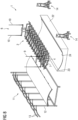
- Fig. 2 shows an enlarged partial view of the transport device 1, with a part of the yoke 2 respectively the yoke carrier 3 and the first end of the yoke 2.
- the illustration shows the gripper elements carrier 4 with the gripper elements 5 attached to a receiving member 15 of the yoke carrier 3.
- Fig. 2 further shows a part of the lifting device 6 with the first rotation unit 7, which comprises a drive motor 16, which is detachable connectable to a rotation shaft 17 of the yoke 2, as shown by the arrow P1.
- the drive motor 16 comprises an electric motor 18 and a gearbox 19 having a receptacle 20, into which the shaft 17 engages.
- the shaft 17 comprises an outer toothing 21, which engages in the receptacle 20, and which is coupled to a gear of the motor driven gearbox 19.
- the mechanical connection between the rotation units 7 and the yoke 2 respectively the drive motor 16 and the rotation shaft 17 is simple, as it is only necessary to insert the rotation shaft 17 into the receptacle 20 realizing the mechanical drive connection. Certainly, this connection is fixated by respective fixation means in order to avoid any unwanted decoupling of the rotation unit 7 from the yoke 2.
- They second rotation unit 8 also comprises a receptacle, into which the rotation shaft 17 at the other end of the yoke engages and is rotatable received in this receptacle.
- This end of the shaft 17 is not toothed, as it is only rotatable received for providing a rotation bearing.
- the connection nevertheless is realized in the same way as explained to the connection of the first rotation units 7. It is only necessary to insert the end of the rotation shaft 17 into the respective receptacle provided at the second rotation unit, realizing the rotation bearing, which connection is certainly also fixated by respective fixation means for avoiding any unwanted decoupling.
- Fig. 3 shows a perspective illustration of a part of the yoke 2 with the yoke carrier 3.
- the yoke carrier 3 is provided with a receptacle 26, into which a shaft element 27 engages and is fixated and secured against rotation.
- the other second end of the yoke 2 respectively the yoke carrier 3 is also provided with such a receptacle and a second shaft element, wherein at this second end, where no toothing is provided, also a simple cylindrical end of the yoke carrier 3, which acts as a pin or pivot, is sufficient.
- the yoke 2 is connected in rotatable bearings to the rotation units 7, 8 at both opposing ends of the yoke 2.
- the yoke 2 is positioned above a preform mold 22 having a concave mold surface 23, on which a preform element 24 is built by arranging a layer stack of fiber mats or fiber fabric, which is embedded in a polymer binder matrix.
- the preform element 24 adapts to the shape of the concave mold surface 23, wherein the shape of the gripper element carriers 4 and the arrangement of the gripper elements 5 also corresponds to this concave form.
- the gripper elements 5 are vacuum grippers.
- a vacuum pump 25 is arranged at the second rotation unit 8 and is therefore, just like the drive motor 16, part of the lifting device 6, but not of the yoke 2.
- the vacuum pump 25 is connected to one or several hoses, which are connected to the vacuum gripper elements 5, so that a vacuum can be drawn, and the gripper elements 5 can suck to the surface of the preform element 24 for firmly fixating the preform element.
- the figs. 4 to 9 show the operation of the transport device 1, with the situation shown in fig. 1 as the starting point.
- the gripper elements 5 have gripped the preform element 24, as explained to fig. 1 .
- This preform element 24 shall be transported to the rack 11.
- the lifting device 6 lifts the rotation units 7, 8 and with them the yoke 2, which, as mentioned, is connected via the carrier 3 and the rotation shaft 17 to both rotation units 7, 8.
- the yoke 2 is connected at both ends to the lifting device 6 respectively both rotation units 7, 8, no tilting occurs when they yoke 2 is lifted, as long as the center of gravity of the preform element is within the area defined by the lifting points.
- the connection at both ends prohibits any kind of tilting.
- the yoke 2 When the yoke 2 is sufficiently lifted, it is rotated, as shown in fig. 5 and 6 , by means of the drive motor 16 coupled to the rotation shaft 17. At the end of this rotation of the yoke 2 around the horizontal axis, the yoke 2 has turned upside down for 180°, so that the preform element 24, which was at the beginning of the operation at the bottom, is now on top, see fig. 6 . Due to the connection of the yoke 2 at both ends to the lifting device, no tilting occurs also during this rotating motion.
- the lifting device 6 moves horizontally over the rack 11 and, when reaching this final horizontal position, lowers the yoke 2, so that the gripper element carriers 4 engage between the receiving elements 13 and the preform element 24 rests on the receiving elements 13, as shown in fig. 7 .
- the they vacuum gripper elements 5 are detached from the preform element 24 by stopping the vacuum pump 25, whereafter the lifting device 6 lowers the yoke 2 a little bit, so that it is distanced from the preform element 24 and the receiving elements 13 and can be moved horizontally by a reverse movement of the lifting device 6.
- the drive motor 16 rotates the empty yoke 2 back to the original position, in which it is transferred back over the preform mold 22, on which another preform element 24 was built, which is, in the next cycle, gripped and moved to the rack 11, as explained previously.
- the rack 11 is adapted to receive three separate preform elements 24 on the respective receiving elements 13, which are arranged in different height levels and are sufficiently distanced from another, so that the empty yoke 2 can easily be moved out of the rack 11 by a horizontal movement of the lifting device 6.
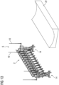
- Figs 10 to 15 show the possibility of a maintenance operation of the yoke 2.
- the empty yoke 2 is lifted, see fig. 10 , by the lifting device 6, whereafter it is rotated by the drive rotor 16 around the horizontal axis provided by the rotation shaft. This rotation is for approximately 90°, as shown in fig. 11 .
- Both service racks 14 are provided with receptacles 28 adapted to receive the rotation shaft ends respectively the shaft elements 17 arranged at both ends of the yoke 2.
- the yoke 2 When the yoke 2 is aligned with the service racks 14 respectively the receptacles 28, the yoke 2 is lowered by the lifting device 6, so that the ends of the rotation shaft respectively the shaft elements 17 engage into the receptacles 28, where they are rotatable received.
- both the first and the second rotation unit 7, 8 are detached from the ends of the yoke 2, see fig. 14 , so that the lifting device 6 may be removed back to the preform mold 22, as shown in fig. 15 .
- the yoke 2 is received at the service racks 14.
- a maintenance worker 29 can now perform maintenance work at the yoke 2 respectively the gripper elements 5, as for example shown in fig. 15 .
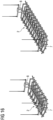
- fig. 16 shows and other benefit of the inventive transport device 1.
- both the first and second rotation unit 7, 8 are detectably attached to the respective yoke 2.
- the connection is simply mounted respectively detached, so that it is possible to quickly connect the lifting device 6 respectively the rotation units 7, 8 to another yoke 2.
- Fig. 16 shows two embodiments, wherein in the embodiment shown to the left a first short yoke 2 to is connected to the rotation units 7, 8, while in the embodiment shown to the right a second longer yoke 2 is connected to the rotation units 7, 8.
- This illustration shall only show the changeability of the inventive transport device respectively the transport system.
- fig. 16 shows two yokes 2 having different length, it is certainly also possible to change from a first yoke 2 having a convex arrangement of the gripper elements 5 to a second yoke 2 having a concave arrangement of the gripper elements 5.
Landscapes
- Engineering & Computer Science (AREA)
- Mechanical Engineering (AREA)
- Robotics (AREA)
- Chemical & Material Sciences (AREA)
- Composite Materials (AREA)
- Blow-Moulding Or Thermoforming Of Plastics Or The Like (AREA)
- Specific Conveyance Elements (AREA)
- Processing And Handling Of Plastics And Other Materials For Molding In General (AREA)
Priority Applications (3)
| Application Number | Priority Date | Filing Date | Title |
|---|---|---|---|
| EP23213603.6A EP4563336A1 (fr) | 2023-12-01 | 2023-12-01 | Dispositif de transport |
| PCT/EP2024/081335 WO2025113944A1 (fr) | 2023-12-01 | 2024-11-06 | Dispositif de transport |
| TW113146038A TW202537819A (zh) | 2023-12-01 | 2024-11-28 | 運送裝置 |
Applications Claiming Priority (1)
| Application Number | Priority Date | Filing Date | Title |
|---|---|---|---|
| EP23213603.6A EP4563336A1 (fr) | 2023-12-01 | 2023-12-01 | Dispositif de transport |
Publications (1)
| Publication Number | Publication Date |
|---|---|
| EP4563336A1 true EP4563336A1 (fr) | 2025-06-04 |
Family
ID=89073094
Family Applications (1)
| Application Number | Title | Priority Date | Filing Date |
|---|---|---|---|
| EP23213603.6A Pending EP4563336A1 (fr) | 2023-12-01 | 2023-12-01 | Dispositif de transport |
Country Status (3)
| Country | Link |
|---|---|
| EP (1) | EP4563336A1 (fr) |
| TW (1) | TW202537819A (fr) |
| WO (1) | WO2025113944A1 (fr) |
Citations (2)
| Publication number | Priority date | Publication date | Assignee | Title |
|---|---|---|---|---|
| EP3750841A1 (fr) * | 2019-06-11 | 2020-12-16 | NEXTER Systems | Dispositif de manutention d'un panneau rigide et procédé de manutention utilisant un tel dispositif |
| EP4249418A1 (fr) * | 2022-03-25 | 2023-09-27 | Siemens Gamesa Renewable Energy A/S | Outil de levage pour lever un élément de construction et procédé de levage d'un élément de construction |
-
2023
- 2023-12-01 EP EP23213603.6A patent/EP4563336A1/fr active Pending
-
2024
- 2024-11-06 WO PCT/EP2024/081335 patent/WO2025113944A1/fr active Pending
- 2024-11-28 TW TW113146038A patent/TW202537819A/zh unknown
Patent Citations (2)
| Publication number | Priority date | Publication date | Assignee | Title |
|---|---|---|---|---|
| EP3750841A1 (fr) * | 2019-06-11 | 2020-12-16 | NEXTER Systems | Dispositif de manutention d'un panneau rigide et procédé de manutention utilisant un tel dispositif |
| EP4249418A1 (fr) * | 2022-03-25 | 2023-09-27 | Siemens Gamesa Renewable Energy A/S | Outil de levage pour lever un élément de construction et procédé de levage d'un élément de construction |
Also Published As
| Publication number | Publication date |
|---|---|
| WO2025113944A1 (fr) | 2025-06-05 |
| TW202537819A (zh) | 2025-10-01 |
Similar Documents
| Publication | Publication Date | Title |
|---|---|---|
| DK2499013T3 (en) | DEVICE FOR REPLACING A BATTERY FOR SUPPLY OF A drive motor IN A MOTOR VEHICLE | |
| EP2345811B1 (fr) | Pince pour fixer la pale d'une éolienne et procédé d'installation de pales d'éolienne | |
| TWI874935B (zh) | 用於抬升建造元件的抬升軛部以及用於抬升建造元件的方法 | |
| WO2003101879A1 (fr) | Appareil de transport de substrat a deux bras | |
| US20020029701A1 (en) | Flexible transporting apparatus for presses | |
| EP4563336A1 (fr) | Dispositif de transport | |
| US11692525B2 (en) | Method of mounting a blade to or unmounting a blade from a rotor hub of a wind turbine | |
| CA2352956A1 (fr) | Appareil et methodes de bobinage et de transfert de stators pour machines dynamoelectriques | |
| CN212887386U (zh) | 一种移位装置 | |
| JP2000044268A (ja) | 光ファイバ母材搬送装置 | |
| EP4516492A1 (fr) | Fourche de levage | |
| EP1151970A2 (fr) | Mécanisme d'inversion pour une machine de fabrication d' objets en verre creux | |
| EP4646530A1 (fr) | Fourche de levage et procédé de placement et de positionnement d'articles sur une surface interne d'une moitié de coque d'une pale d'éolienne | |
| CN209935286U (zh) | 收放板机 | |
| EP4390118A1 (fr) | Crémaillère pour la fabrication d'éléments préfabriqués et/ou de préforme, système de fabrication et dispositif d'assistance au treuil | |
| CN219057455U (zh) | 一种电视生产线传送装置 | |
| EP4389383A1 (fr) | Dispositif de support d'élément de moule pour un ensemble de fabrication d'éléments préformés et/ou prémoulés et/ou préemballés | |
| CN216993070U (zh) | 一种塑料盒覆膜机工位转换机构 | |
| CN218370417U (zh) | 一种剔板机 | |
| CN217577308U (zh) | 一种工业铝材加工流水线全自动送料装置 | |
| CN120135796B (zh) | 一种板材固化加工装载装置 | |
| CN217972487U (zh) | 一种货物转运叉取机构 | |
| CN121590812A (zh) | 一种旋转式储料装置及旋转式储料容器的手套包装系统 | |
| EP4722530A1 (fr) | Dispositif de garniture pour la garniture d'un composant de racine ronde préfabriqué et procédé de fabrication d'un composant de racine ronde | |
| CN119787753A (zh) | 一种电机转子的自动化组装设备 |
Legal Events
| Date | Code | Title | Description |
|---|---|---|---|
| PUAI | Public reference made under article 153(3) epc to a published international application that has entered the european phase |
Free format text: ORIGINAL CODE: 0009012 |
|
| STAA | Information on the status of an ep patent application or granted ep patent |
Free format text: STATUS: THE APPLICATION HAS BEEN PUBLISHED |
|
| AK | Designated contracting states |
Kind code of ref document: A1 Designated state(s): AL AT BE BG CH CY CZ DE DK EE ES FI FR GB GR HR HU IE IS IT LI LT LU LV MC ME MK MT NL NO PL PT RO RS SE SI SK SM TR |
|
| STAA | Information on the status of an ep patent application or granted ep patent |
Free format text: STATUS: THE APPLICATION IS DEEMED TO BE WITHDRAWN |